Sign In
Upload
Manuals
Brands
rtd Manuals
Computer Hardware
CMX158886
rtd CMX158886 Manuals
Manuals and User Guides for rtd CMX158886. We have
1
rtd CMX158886 manual available for free PDF download: User Manual
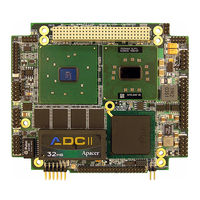
rtd CMX158886 User Manual (120 pages)
cpuModules
Brand:
rtd
| Category:
Computer Hardware
| Size: 3 MB
Table of Contents
Cmx158886 Cpumodules
1
Table of Contents
5
Chapter 1 Introduction
11
CMX158886 Cpumodules
12
Enhanced Intel Speedstep (PX Only)
13
Thermal Monitor
13
Error-Correction Codes (Selected Models Only)
13
Adio with Wake-On-Adio
13
Ordering Information
15
CMX158886 Model Options
15
Cable Kits and Accessories
16
Board Features
17
I/O
18
Bios
19
Block Diagram
21
Specifications
22
Physical Characteristics
22
Power Consumption
22
Operating Conditions
22
Electrical Characteristics
22
Contact Information
25
Chapter 2 Getting Started
27
Connector Locations
28
Connecting the Utility Cable
30
Connecting a Keyboard
30
Connecting to the PC/104-Plus (PCI) Bus
30
Slot Selection Switches
31
PCI Bus Expansion Card Power
31
Volt DC
31
PCI Bus Signaling Levels
31
Booting the CMX158886 Cpumodule for the First Time
32
Chapter 3 Connecting the Cpumodule
33
Proper Grounding Techniques
34
Connector Locations
34
Auxiliary Power (CN3)
36
Utility Port Connector (CN5)
38
Speaker
38
Keyboard
39
Mouse
39
System Reset
39
Soft Power Button
39
Battery
40
SVGA Video Connector (CN18)
41
LVDS Flat Panel Video Connector (CN19)
43
EIDE Connector (CN10)
44
ATA/IDE Disk Chip Socket (U16)
45
Installing and Configuring the ATA/IDE Disk Chip
45
Serial Port 1 (CN7) and Serial Port 2 (CN8)
47
Serial Port UART
47
Serial Port (Default)
47
RS-422 or RS-485 Serial Port
48
RS-422 and RS-485 Mode Pinout
49
Dual Serial Port Modes
50
Multiport™ (CN6)
52
Multiport Configured as an Advanced Digital I/O (Adio™) Port
52
Multiport Configured as a Parallel Port
53
Multiport Configured as a Floppy Drive Controller
54
USB 2.0 Connector (CN17)
55
Ethernet (10/100Base-T and -TX) Connector (CN20)
57
Audio (CN11)
58
PC/104-Plus PCI Bus (CN16)
59
PC/104-Plus PCI Bus Signals
60
Address and Data
60
Interface Control Pins
60
Error Reporting
60
Arbitration (Bus Masters Only)
60
System
60
Interrupts
60
Power Supplies and VIO
61
ATX Power Management Signals (Optional)
61
Bridge Link (CN4)
62
External Power Management (CN12)
63
Optional RTC Battery Input (CN13)
63
Fan Power, +5 V (CN14)
63
Fan Power, Switched (CN15)
64
Chapter 4 Using the Cpumodule
65
The RTD Enhanced AMI BIOS
66
Configuring the RTD Enhanced AMI BIOS
66
Entering the BIOS Setup
66
Field Selection
66
Main Menu Setup Fields
67
Power on Self Test (POST) Codes
67
Booting to Boot Block Flash with Fail Safe Boot ROM
68
Memory Map
69
I/O Address Map
70
Hardware Interrupts
71
Multiport: Advanced Digital I/O Ports (Adio™)
72
Digital I/O Register Set
72
Port 1 Data Register Is a Read/Write Byte Direction
74
Interrupts
74
Advanced Digital Interrupts
74
Event Mode
74
Match Mode
74
Strobe Mode
75
Wake-On-Adio
75
Multiport: Parallel Port Control
76
Multiport: Floppy Drive
76
AC'97 Audio
76
Ethernet (10/100Base-T and -TX)
76
IDE Controller Configuration
77
Cable Modes
77
Cable Detection
77
Device and Host Mode
77
Host Determination of Cable Type
77
Device Detect
77
Legacy Mode and Native Mode IDE
78
Legacy Mode
78
Native Mode
78
Configuring the ATA/IDE Disk Chip Socket
78
Real Time Clock Control
79
Overview
79
Accessing the RTC Registers
79
Watchdog Timer Control
81
Thermal Management
82
Thermal Monitor
82
Fan Mode
82
Further Temperature Reduction
82
Power Management
83
Enabling Enhanced Intel Speedstep Technology (PX Only)
83
Advanced Configuration and Power Interface (ACPI)
83
Power Button Modes
83
Low-Power Wake Options
83
AT Vs. ATX Power Supplies
84
ATX Power Supply Signals
84
Reducing Power Consumption
85
Multi-Color LED
86
Reset Status Register
87
DVMT Mode Select
89
User EEPROM
90
Features and Settings that Can Affect Boot Time
91
Quick Boot
91
Add-On Cards with BIOS Extensions
91
VGA Controller
91
Hard Drive Type
91
Monitor Type
91
NVRAM Updates
91
Boot Device Order
91
System Recovery
92
Loading Default BIOS Settings
92
Booting to the Fail Safe Boot ROM (FSBR)
92
Basic Interrupt Information for Programmers
93
What Happens When an Interrupt Occurs
93
How Long Does It Take to Respond to an Interrupt
93
Interrupt Request Lines
93
Intel 8259 Programmable Interrupt Controller
94
PCI Interrupts
94
Writing an Interrupt Service Routine (ISR)
94
Sample Code
94
Appendix A Hardware Reference
95
Jumper Settings and Locations
96
Onboard PCI Devices
98
Physical Dimensions
99
Appendix B Troubleshooting
101
Common Problems and Solutions
102
Troubleshooting a PC/104-Plus System
103
How to Obtain Technical Support
104
Appendix Cidan™ Dimensions and Pinout
105
IDAN Dimensions and Connectors
106
External I/O Connections
107
IDAN Dimensions and Connectors (BRG Version Only)
114
External I/O Connections (BRG Version Only)
115
Appendix D Additional Information
117
Application Notes
117
Drivers and Example Programs
117
Interrupt Programming
117
Serial Port Programming
117
Appendix E Limited Warranty
119
Advertisement
Advertisement
Related Products
rtd cpuModule CMX147786HX
rtd CMX58886CX
rtd cpuModule CMX47786HX
rtd CMX34KB
rtd CMX34KBD2200HR-16834
rtd CMX34KBQ3000HR-16834
rtd CMX34KBD2100HR-16834
rtd cpuModule CMA22MMVD1200HR-2048
rtd cpuModule CMA22MMVD1200HR-1024
rtd cpuModule CML47786HX
rtd Categories
Computer Hardware
Control Unit
PCI Card
Switch
GPS
More rtd Manuals
Login
Sign In
OR
Sign in with Facebook
Sign in with Google
Upload manual
Upload from disk
Upload from URL