
Related Manuals for Pima AlarmView


Summary of Contents for Pima AlarmView
-
Page 1: User Guide
AlarmView Wireless Intruder Alarm System with Visual Verification User Guide System version 2.08.38... - Page 2 Copyright 2013 © PIMA Electronic Systems Ltd. All rights reserved. E&OE This guide and the information contained herein are proprietary to PIMA Electronic Systems Ltd. Only PIMA Electronic Systems Ltd. or its customers have the right to use the information.
-
Page 3: Table Of Contents
Table of contents Introduction ................... 5 Graphic conventions in this guide ..............5 Features ..................... 5 Visual-Verification ..................6 Specifications ....................6 1.4.1 Wireless network .................. 7 1.4.2 Communication ..................7 1.4.3 Physical and electric attributes ............... 7 Quick Reference Guide ................9 System components .................. - Page 4 9.4.1 SMS commands ................. 24 9.4.2 Receiving an SMS message ..............25 Appendixes Appendix A The AlarmView Smartphone Application ....... 26 Installing the application ................26 The interface ..................... 27 Settings ....................28 Operating the application ................28 Appendix B Maintenance &...
- Page 5 Figure index Figure 1. Alarm visual verification ..................6 Figure 2. The Control Panel ..................... 9 Figure 3. The Control Panel keys ..................9 Figure 4. Control Panel’s back side .................. 10 Figure 5. The LCD display ....................10 Figure 6. Info screen example ..................
- Page 6 The use of the software associated with the system is subject to the terms of the license provided as part of the purchase documents. PIMA Electronic Systems Ltd.’s exclusive warranty and liability is limited to the warranty and liability statement provided in A ppendix E on page 43.
-
Page 7: Introduction
1 : Introduction Introduction PIMA Wireless This guide is designed to assist you throughout the use of the AlarmView – a Intruder Alarm System with visual verification. PIMA Wireless products are easy to install, plug-n-play, providing wireless intruder alarm capabilities with or without visual-verification &... -
Page 8: Visual-Verification
Upon alarm event, both the event information and images are transmitted wirelessly to the AlarmView Control Panel; the event code + image are sent over GPRS/GSM network directly to the Central Monitoring Station and/or the mobile phone of the end-user. -
Page 9: Wireless Network
1 : Introduction Codes 8 codes, up to 8 digits each (numeric value 1-4): Master user 4 Regular users (or up to 4 digit code, numeric value 0-9, with external keypad) Duress code Limited 24H code ... - Page 10 AlarmView User Guide Physical Attributes Storage temperature -25ºC - +70ºC -13ºF - 158ºF Humidity 0 to 85%, non condensing Electrical Data Power supply +12VDC/1A Current drain 100mA standby, 0.7A peak Backup battery +4.8 VDC, 4 x Ni-MH 2 Ah, up to 12 hours To prevent damage to the Control Panel, use only the original AC adaptor and backup battery pack.
-
Page 11: Quick Reference Guide
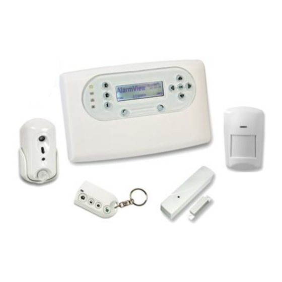
Quick Reference Guide System components The AlarmView system consists of the Control Panel, 23 wireless zones, 1 hardwired, 6 PIR camera (SmartView /OutView) and 36 wireless peripherals - up to 6 Key fobs/ Remote keypads, and 6 Panic buttons, as well as one wireless siren. -
Page 12: Key Definition
AlarmView User Guide Figure 4. Control Panel’s back side 2.2.1 Key definition The table below details the Control Panel’s key definition and functions. Arming keys Description Away Arm to Away (full) mode Home Arm to Home (partial) mode Part Arm to Part (partial)mode... -
Page 13: Status Messages
2 : Quick Reference Guide 2.2.3 Status messages The available system status messages are: Initializing (shown after startup, exiting programming mode and after a system reset Disarm Arm Away Exit Delay Entry Delay Arm Home ... -
Page 14: Info Screen - System Status
AlarmView User Guide Color Behavior Alarm triggered – all modes; blinking will stop White, blinking when re-arming, or entering the system log. INFO screen - system status In the INFO screen you can view the status of all active zones, by pressing the Info right function button (in the main screen). -
Page 15: Options Menu
3 : Options menu Options menu This menu allows changing and controlling the general behavior of the Control Panel. Global settings Options Global Settings T Global Chime T Remote Look-In T Visual Events The Global Settings menu allows to enable/disable the Global Chime, Remote Look-in, and Visual events, to maximize your control of all privacy issues. -
Page 16: Event Log Menu
AlarmView User Guide Event Log menu 21/07/13 05:26:33 Event Log Communication Loss CANCEL The Event Log menu allows viewing the system log. The log keeps the last 256 events. While the system is armed, only 10 events from the same zone can be logged. -
Page 17: Service Menu
5 : Service menu Service menu Tests Service Test Tests Zone Stop Siren External Siren Relearn Built-In Siren Communication GPRS Link System Self Test CMS 1-2 Contact 1-4 Tests help ensuring proper operation of the system. You should test you're alarm system on a regular basis, once every week. -
Page 18: External Siren
AlarmView User Guide 5 bars: Excellent reception; 4 bars: Very good reception; 3 bars: Good reception; 2 bars: Low reception - relocating the detector is advisable; One bar: Poor reception- relocating the detector is required! 5.1.2... -
Page 19: System Self-Test
5 : Service menu 5.1.4.1 Communication test options Type Test Process Target LCD Message Response GPRS An attempt to open www.google.com Wait Passed/Failed © LINK Google 's website Sends a “Periodic Test” event to the CMS (reporting is dependent on the 1...2 protocol defined). -
Page 20: System Version
AlarmView User Guide System version To view the system version: Access the User menu and select Service Display Version. The Control Panel’s software version will be displayed. Press OK to exit. System reset This feature is to be used mainly to reset the GSM communication between the control panel and the GSM network. -
Page 21: Passwords Menu
Installer Regular user passwords Here you can define up to 4 users of the AlarmView, with name and password for each. The passwords only allow their users to arm and disarm the system. The password functionality depends on whether it is entered at the... -
Page 22: Master User Password
AlarmView User Guide Master user password The Master user password is used to access the user menu (and to arm/disarm). This password can be up to 8 digits long and contain the numeric values of 1-4, for example 41241324. The default Master user password must be changed, to complete the installation and setup process. -
Page 23: Set Clock Menu
7 : Set Clock menu Set Clock menu When starting the system for the first time, or after a long power failure, the time and date need to be set. Set Clock 16 34 Time AM-PM/24H CANCEL Date 04 13 DD-MM/MM-DD CANCEL Time... -
Page 24: Stop Communication Menu
AlarmView User Guide Stop Communication menu Stop Comm. Are you sure ? This option allows you to temporarily stop all communication - all pending messages are cancelled and all communication buffers are cleared. The Stop Communication option is used in the following cases: During the installation process (by the Installer). -
Page 25: Operating Instructions
Operating Instructions Arming modes The following section explains how to arm and disarm the AlarmView system, using the various options. All these options are also available when using a remote control, key fob or wireless keypad, or when using SMS commands from an authorized cellular phone. -
Page 26: Force Arm And Faults Overriding
See the “Glossary”, on page 41 for more details. Operating the system by text messages The AlarmView system can be operated by SMS messages. Operations include arming & disarming, requesting the system status, activating the PGM output, stopping the siren and requesting look-in images. -
Page 27: Receiving An Sms Message
* Commands are NOT case sensitive 9.4.2 Receiving an SMS message The SMS messages sent by the Control Panel are built out of the following format: Message + Device Name/User Name + time stamp; for example, "Alarm from Kitchen AlarmView 02:38:26". -
Page 28: Appendix A The Alarmview Smartphone Application
Appendix A The AlarmView Smartphone Application Currently for Android only and soon for iPhone too, the AlarmView application allows you to operate your alarm system via a simple-to-use, icon based, free smartphone application. The application can be obtained by Email, directly from your vendor. -
Page 29: The Interface
A ppendix A: The AlarmView Smartphone Application When installation ends, click Open. The interface Figure 7. The smartphone app’s screen A.2.1 The buttons Turn On/Off the PGM output Arm Away Green: the output is active Red: the output is not active... -
Page 30: Settings
A.4.1 Arming & disarming To perform an action, just tap the appropriate icon. The AlarmView’s Control Panel will send a confirmation (or error) message, as soon as the action (e.g., disarming the system) is taken; the relevant icons in the application will be colored: arming icons lights in red when active, disarm(ed) - Page 31 A ppendix A: The AlarmView Smartphone Application Also, the status icons will light in green, depending to their status: low battery in green (otherwise in gray), faults in green when there ones, and so on. A.4.2 Look-in image request Tap the camera icon at the bottom - a pop-up window showing the cameras, is displayed (see the next image).
-
Page 32: Appendix B Maintenance & Troubleshooting
AlarmView User Guide Appendix B Maintenance & Troubleshooting Cleaning the LCD screen The LCD screen may occasionally get finger oil stains and accumulate dust. Clean it only with a soft dry cloth or a special screen cleanser. Avoid the use of abrasives of any kind. -
Page 33: Figure 8. Remove Bracket
A ppendix B: Maintenance & Troubleshooting Use suitable replacement batteries from Pima Alarm Systems for best performance and system care. Replacing the SmartView battery The battery used in the SmartView detector is Energizer Lithium L91 1.5v. To Replace the SmartView battery: Release the screw fastening the bracket to the detector and remove the bracket. -
Page 34: Smartview Pir/Camera
AlarmView User Guide Appendix C Wireless Peripherals This section gives a detailed explanation of each of the available SmartView family and additional Wireless detectors and peripherals. SmartView PIR/Camera The SmartView is a supervised wireless digital PIR motion detector, combined with a VGA high-quality color camera. -
Page 35: Td-5 Temperature Detector
While the AlarmView system is disarmed, every time a magnet door or window is opened, the Control Panels chime sounds a long beep. While the system is armed, however, an alarm is generated, just like any other detector. -
Page 36: Sm Smoke Detector
AlarmView User Guide SM smoke detector The smoke detector has a small foot print and low profile, yet it utilizes optical chamber technology, freeing it from potentially harmful radioactive materials. It is micro-process controlled and offers 100% reliability, safety and quality. -
Page 37: Kf-1/Kf-2 Remote Control Key Fobs
A ppendix C: Wireless Peripherals C.7.1 Test Press the Test button on the CO Detector to ensure that it is functioning properly: If the detector functions normally, the LED will be on for 2 sec. then it will sound a beep. ... -
Page 38: Rwk Wireless Keypad
AlarmView User Guide C.8.2 Replacing the key fob's battery Remove the battery cover by using a coin to turn it counter-clockwise Insert the battery as shown in the diagram, with the unmarked side (negative) of the battery facing down Replace the battery cover Secure the cover by using a coin to turn clockwise;... -
Page 39: Rep Range Extender (Repeater)
A ppendix C: Wireless Peripherals C.9.3 LED indicators The remote wireless keypad LED indicators behave as follows: Power LED (Red): Steady: system OK Flashing: low battery Status LED (tricolor) Steady Red: armed Away Flashing Red: armed Home ... -
Page 40: C.11 Pcp Panic Pendant/Wrist Watch
AlarmView User Guide C.11 PCP Panic Pendant/Wrist watch The water proof panic pendant/wrist watch is designed to be worn by people with special care needs, as they move around the premises. Figure 20. Panic pendant/wrist watch C.11.1 Use instructions To transmit an emergency signal to the Control Panel, press and hold the Panic button (see next figure) for more than one second. -
Page 41: C.13 Sir-I Wireless Indoor Siren
A ppendix C: Wireless Peripherals Insert new batteries and slide Power Switch back to ON position. The Bell box will beep and flash when the last battery is inserted. Replace the battery compartment lid with the four screws and not to over tighten. C.13 SIR-I Wireless Indoor siren The Indoor Wireless Siren can be used is commercial, industrial and residential indoor locations. -
Page 42: C.14 Wld Wireless Water Leakage Detector
AlarmView User Guide C.13.4 Replacing the batteries Release the side screw of the box and lift the outer case carefully. Remove the battery compartment lid’s 4 screws and take it off. Remove all 4 batteries. Press the Tamper switch twice to discharge. -
Page 43: Appendix D Glossary
A ppendix D: Glossary Appendix D Glossary Alarm types: Burglary Alarm – An alarm caused by a violation of one or more of the zones. Fire Alarm – An alarm initiated due to a violation of one or more of the fire zones ... - Page 44 AlarmView User Guide Door Contact – A detector comprising a magnetically operated reed switch and a separate magnet. Usually used on doors and windows to detect whether the door or window is opened or closed. Key fob – A small remote control that can be used to arm/disarm the system.
-
Page 45: Appendix E Limited Warranty
Appendix E Limited Warranty PIMA Electronic Systems Ltd. ("the Manufacturer") warrants its products hereinafter referred to as "the Product" or "Products" to be in conformance with its own plans and specifications and to be free of defects in materials and workmanships under normal use and service for a period of twelve (12) months from the date of shipment by the Manufacturer. -
Page 46: Appendix F Useful Tables
A ppendix F: Useful tables Appendix F Useful tables Wireless Zones Zone Name Zone Type Location Sensor Type Comments Visual Zones Key fobs/Remote Control users Emergency Devices No. User No. User Type Panic / Emergency Panic / Emergency Panic / Emergency Panic / Emergency Panic / Emergency Panic / Emergency... - Page 48 Pima Electronic Systems Ltd. 5 Hatzoref st., Holon 5885633 ISRAEL Tel: +972.3.650.6414 Fax: +972.3.550.0442 E-mail: support@pima-alarms.com sales@pima-alarms.com www.pima-alarms.com Distributed and Supported by: P/N: 4410374 *4410374* Version: XX en, A3 (July 2013)
Need help?
Do you have a question about the AlarmView and is the answer not in the manual?
Questions and answers