Table of Contents
Advertisement
Quick Links
Advertisement
Table of Contents

Related Manuals for Advantech AIMB-C200


Summary of Contents for Advantech AIMB-C200
- Page 1 User Manual AIMB-C200 Economical Embedded Chassis for Mini-ITX Motherboard...
- Page 2 Because of Advantech’s high quality-control standards and rigorous testing, most of our customers never need to use our repair service. If an Advantech product is defec- tive, it will be repaired or replaced at no charge during the warranty period. For out- of-warranty repairs, you will be billed according to the cost of replacement materials, service time and freight.
-
Page 3: Packing List
Before setting up the system, check that the items listed below are included and in good condition. If any item is not in accord with the table, please contact your dealer immediately. One AIMB-C200 Unit One User Manual One Warranty Card... - Page 4 Technical Support and Assistance Visit the Advantech website at www.advantech.com/support where you can find the latest information about the product. Contact your distributor, sales representative, or Advantech's customer service center for technical support if you need additional assistance. Please have the following information ready before you call: –...
-
Page 5: Safety Instructions
The sound pressure level at the operator's position according to IEC 704-1:1982 is no more than 70 dB (A). DISCLAIMER: This set of instructions is given according to IEC 704-1. Advantech disclaims all responsibility for the accuracy of any statements contained herein. - Page 6 Don't touch any components on the CPU card or other cards while the PC is on. Disconnect power before making any configuration changes. The sudden rush of power as you connect a jumper or install a card may damage sensitive elec- tronic components. AIMB-C200 User Manual...
-
Page 7: Table Of Contents
Figure 3.3 The Rear Panel of AIMB-C200-BARE...... 13 Installing the System Cooling Fan............13 Figure 3.4 Installing the System Cooling Fan ......13 Replacing the Power Supply of AIMB-C200-55ZE........14 Figure 3.5 Replacing the Power Supply of AIMB-C200-55ZE ... 14 Appendix A Exploded Diagram ......15 Exploded Diagram of AIMB-C200 ............ - Page 8 AIMB-C200 User Manual viii...
-
Page 9: Chapter 1 General Information
Chapter General Information... -
Page 10: Specifications
Specifications Table 1.1: General Features of AIMB-C200-55ZE Chassis Contruction Heavy-duty steel with Aluminum Front Panel Disk Drive Bay Internal 2.5" Front USB I/O Interface Reserve cutout 1 x LVDS, 1 x Antenna Cooling System System Fan 1 (optional) LED indicators... -
Page 11: Dimensions
Dimensions AIMB-C200-55ZE AIMB-C200-BARE 65[2.56] 230[9.06] Figure 1.1 Dimensions AIMB-C200 User Manual... - Page 12 AIMB-C200 User Manual...
-
Page 13: Chapter 2 System Setup And Maintenance
Chapter System Setup and Maintenance... -
Page 14: Removing The Chassis Cover
Removing the Chassis Cover Figure 2.1 Removing the Chassis Cover Removing the 2.5" HDD Driver Bay Figure 2.2 Removing the 2.5" HDD Driver Bay AIMB-C200 User Manual... -
Page 15: Installing The Motherboard
Installing the Motherboard Figure 2.3 Installing the I/O Port Bracket Figure 2.4 Installing the Motherboard AIMB-C200 User Manual... -
Page 16: Installing The Disk Drive And Driver Bay
Installing the Disk Drive and Driver Bay Figure 2.5 Installing the Disk Drive and Driver Bay Installing the Bottom Side Mounting Brackets Figure 2.6 Installing the Bottom Side Mounting Brackets AIMB-C200 User Manual... -
Page 17: Installing The Chassis Cover
Installing the Chassis Cover Figure 2.7 Installing the Chassis Cover AIMB-C200 User Manual... - Page 18 AIMB-C200 User Manual...
-
Page 19: Chapter 3 Operation
Chapter Operation... -
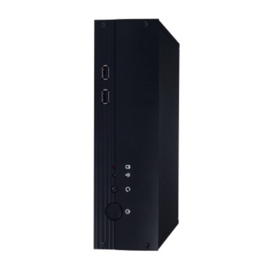
Page 20: The Front Side
3.1.2 LED Indicators Table 3.1: Definition of LED indicators Light Icon Description No light Power Power Normal Off or failure No reading Reading The Rear Side 3.2.1 AIMB-C200-55ZE Antenna LVDS Figure 3.2 The Rear Panel of AIMB-C200-55ZE AIMB-C200 User Manual... -
Page 21: Aimb-C200-Bare
3.2.2 AIMB-C200-BARE Antenna LVDS Figure 3.3 The Rear Panel of AIMB-C200-BARE Installing the System Cooling Fan Figure 3.4 Installing the System Cooling Fan AIMB-C200 User Manual... -
Page 22: Replacing The Power Supply Of Aimb-C200-55Ze
Replacing the Power Supply of AIMB-C200-55ZE Figure 3.5 Replacing the Power Supply of AIMB-C200-55ZE AIMB-C200 User Manual... -
Page 23: Appendix A Exploded Diagram
Appendix Exploded Diagram... -
Page 24: Exploded Diagram Of Aimb-C200
Exploded Diagram of AIMB-C200 Front bezel Sysem Fan Fron USB Board Button Side Mounting Brackets Front Panel Button Holder Top Cover Power Supply MB I/O Port Bracket Motherboard Figure A.1 Exploded Diagram of AIMB-C200 AIMB-C200 User Manual... -
Page 25: Appendix B Motherboard Options
Appendix Motherboard Options... -
Page 26: Motherboard Options
Motherboard Options Table B.1: Motherboard Options Motherboard Chassis Model Name AIMB-C200-55ZE AIMB-210/252/270 AIMB-C200-BARE AIMB-212 AIMB-C200 User Manual... - Page 27 AIMB-C200 User Manual...
- Page 28 No part of this publication may be reproduced in any form or by any means, electronic, photocopying, recording or otherwise, without prior written permis- sion of the publisher. All brand and product names are trademarks or registered trademarks of their respective companies. © Advantech Co., Ltd. 2010...
Need help?
Do you have a question about the AIMB-C200 and is the answer not in the manual?
Questions and answers