
Related Manuals for IBM 1000 VA LCD


Summary of Contents for IBM 1000 VA LCD
- Page 1 1000 VA LCD Tower UPS and 1500 VA LCD Tower UPS Installation and Maintenance Guide...
- Page 3 1000 VA LCD Tower UPS and 1500 VA LCD Tower UPS Installation and Maintenance Guide...
- Page 4 Note: Before using this information and the product it supports, read the general information in Appendix B, “Notices,” on page 49, the Safety Information and Environmental Notices and User Guide documents on the IBM Documentation CD, and the Warranty Information document that comes with the product.
- Page 5 Vor der Installation dieses Produkts die Sicherheitshinweise lesen. Prima di installare questo prodotto, leggere le Informazioni sulla Sicurezza. Les sikkerhetsinformasjonen (Safety Information) før du installerer dette produktet. Antes de instalar este produto, leia as Informações sobre Segurança. © Copyright IBM Corp. 2010...
- Page 6 Antes de instalar este producto, lea la información de seguridad. Läs säkerhetsinformationen innan du installerar den här produkten. Important: Each caution and danger statement in this document is labeled with a number. This number is used to cross reference an English-language caution or danger statement with translated versions of the caution or danger statement in the Safety Information document.
- Page 7 DANGER When working on or around the system, observe the following precautions: Electrical voltage and current from power, telephone, and communication cables are hazardous. To avoid a shock hazard: v Connect power to this unit only with the provided power cord. Do not use the provided power cord for any other product.
- Page 8 To avoid possible explosion, do not burn. Exchange only with the IBM-approved part. Recycle or discard the battery as instructed by local regulations. In the United States, IBM has a process for the collection of this battery. For information, call 1-800-426-4333. Have the IBM part number for the battery unit available when you call.
-
Page 9: Table Of Contents
Chapter 1. Introduction ..... . 1 The IBM Documentation CD ....2 Hardware and software requirements . - Page 10 Hardware service and support ....48 IBM Taiwan product service ....48 Appendix B.
-
Page 11: Chapter 1. Introduction
Each uninterruptible power supply has the following communication features: an RS-232 port, a USB port, and a communication bay for an optional IBM Network Management Card. An IBM Environmental Monitoring Probe is also available. -
Page 12: The Ibm Documentation Cd
Note: The illustrations in this document might differ slightly from your hardware. The IBM Documentation CD The IBM Documentation CD contains documentation for your uninterruptible power supply in Portable Document Format (PDF) and includes the IBM Documentation Browser to help you find information quickly. Hardware and software requirements... - Page 13 To search all the documents, type a word or word string in the Search field and click Search. The documents in which the word or word string is displayed are listed in order of the most occurrences. Click a document to view it, and press Ctrl+F to use the Acrobat search function, or press Alt+F to use the xpdf search function within the document.
-
Page 14: Specifications
The specifications of the uninterruptible power supply models are shown in the following tables. Note: All dimensions include the front bezel. Table 1. 1000 VA LCD tower uninterruptible power supply specifications 1000 VA LCD tower 1000 VA LCD tower 1000 VA LCD tower... - Page 15 Table 2. 1500 VA LCD tower uninterruptible power supply specifications 1500 VA LCD tower 1500 VA LCD tower 1500 VA LCD tower uninterruptible power uninterruptible power uninterruptible power Specification supply (120 V) supply (100 V) supply (230 V) Height 246 mm (9.7 in.) 246 mm (9.7 in.) 246 mm (9.7 in.) Width...
-
Page 16: Internal Circuit Configuration
Notices and statements in this document The caution and danger statements in this document are also in the multilingual Safety Information document, which is on the IBM Documentation CD. Each statement is numbered for reference to the corresponding statement in the Safety Information document. -
Page 17: Chapter 2. Installing The Uninterruptible Power Supply
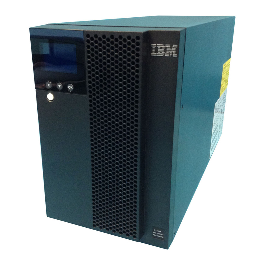
Note: Your uninterruptible power supply model might not come with all of the items in the following list. v Uninterruptible power supply v Documentation package v IBM UPS Manager CD (power-management software) v Serial and USB communication cables v Remote emergency power-off connector Front view of the uninterruptible power supply The following illustration shows the front view of the uninterruptible power supply. -
Page 18: Rear View Of The Uninterruptible Power Supply
Note: The shaded areas that are shown in the following illustrations indicate the load segment groupings. The shading does not appear on the chassis. 1000 VA LCD tower uninterruptible power supply (100 V) 1000 VA and 1500 VA LCD Tower UPS: Installation and Maintenance Guide... -
Page 19: 1000 Va Lcd Tower Uninterruptible Power Supply (120 V)
1000 VA LCD tower uninterruptible power supply (120 V) Remote emergency Uninterruptible power-off port power supply communication bay (for optional network REPO management card) connector RS-232 connector Two NEMA 5-15R receptacles (Load segment 1) NEMA 5-15R IEC 320-C14 receptacles inlet connector... -
Page 20: 1500 Va Lcd Tower Uninterruptible Power Supply (100 V)
1500 VA LCD tower uninterruptible power supply (100 V) 1500 VA LCD tower uninterruptible power supply (120 V) Remote emergency Uninterruptible power-off port power supply communication bay (for optional network REPO management card) connector RS-232 connector Two NEMA 5-15R receptacles (Load segment 1) NEMA 5-15R IEC 320-C14... -
Page 21: 1500 Va Lcd Tower Uninterruptible Power Supply (230 V)
1500 VA LCD tower uninterruptible power supply (230 V) Remote emergency Uninterruptible power-off port power supply communication bay (for optional network REPO management card) connector RS-232 connector Two IEC 320-C13 receptacles (Load segment 1) Six IEC 320-C13 IEC 320-C14 receptacles inlet connector (Load segment 2) Chapter 2. -
Page 22: Connecting The Internal Battery
Connecting the internal battery To connect the uninterruptible power supply internal battery, complete the following steps: 1. Make sure that the uninterruptible power supply is turned off and is disconnected from the outside power source. 2. Remove the uninterruptible power supply front bezel: a. - Page 23 4. Connect the internal battery connectors. Note: A small amount of arcing might occur when you connect the batteries. This is normal and does not damage the unit or present any safety concern. 5. Replace the metal battery cover: a. Align the battery cover over the internal battery. b.
-
Page 24: Completing The Installation
To complete the installation of the uninterruptible power supply, complete the following steps: 1. If you are installing the IBM UPS Manager software, connect a computer to the uninterruptible power supply by using one of the communication cables that come with the uninterruptible power supply. -
Page 25: Installing The Remote Emergency Power-Off
Installing the remote emergency power-off The uninterruptible power supply includes a remote emergency power-off connector that enables you to turn off power at the uninterruptible power supply output receptacles from a customer-supplied switch in a remote location. For example, you can use this feature to shut down the load and the uninterruptible power supply by thermal relay, in the event of a room overtemperature condition. - Page 26 Note: Make sure that no jumper is installed in the remote emergency power-off connector. If a jumper is installed, remove it before you connect to the remote emergency power-off connector. 3. Install the remote emergency power-off connector in the remote emergency power-off port on the rear of the uninterruptible power supply.
-
Page 27: Uninterruptible Power Supply Initial Startup
4. Connect the uninterruptible power supply power cord to a power outlet. The uninterruptible power supply front panel display is lit. The IBM startup screen changes to the uninterruptible power supply status summary screen. Standby status is displayed on the front panel of the uninterruptible power supply. - Page 28 10. To prevent an uninterruptible power supply overload condition, connect one load at a time and make sure that each protected device starts up completely before you connect the next load. Notes: 1. At initial startup, the uninterruptible power supply sets system frequency according to input line frequency (input frequency auto sensing is enabled by default).
-
Page 29: Chapter 3. Operating The Uninterruptible Power Supply
OK: Press this button to select the current menu or option. On the following screens, press and hold this button longer than 1 second: v On the User Setting screens, to save the displayed setting. © Copyright IBM Corp. 2010... -
Page 30: Operating Modes
v On the Meter and Notice/Alarm screens, to lock the screen (prevent the screen from returning to its default after timeout). A locked screen displays a small key image near the status icon. To unlock the screen, press any button to perform its usual function. -
Page 31: Starting The Uninterruptible Power Supply On Battery
To turn on the uninterruptible power supply, press the on/off button for approximately 1 second. The display changes from the start screen to the uninterruptible power supply Status Summary screen and shows the Standby icon flashing while the uninterruptible power supply starts. Note: If the uninterruptible power supply is shut down completely, you must set the date and time (see Table 8 on page 24). -
Page 32: System Status
System status The System Status provides the following information: v Battery status, including state and change level v Status summary (load percentage, output power, output voltage and frequency, and mode) v Notice or alarm status, if any are present If the message ALARM is displayed, press the down ( ) button to display the active notices, alarms, and battery status messages. -
Page 33: Control Screens
UPS firmware: Firmware version for the uninterruptible power supply Note: The network management card firmware screens are displayed only if an IBM Network Management Card is installed. See “IBM Network Management Card” on page 32. Chapter 3. Operating the uninterruptible power supply... -
Page 34: Configuration
Configuration Only the available options are displayed. User settings are not protected by default. You can enable the password through the User Password setting. The following table describes the options that you can change. Table 8. Configuration settings Description Available settings Default setting Change language [English] [French] [German] [Spanish] [Japanese] [Simplified... -
Page 35: Retrieving The Alarm History
Table 8. Configuration settings (continued) Description Available settings Default setting Overload alarm level [10%] [20%] [30%]...[100%] 100% If 100%, the uninterruptible power supply issues an Output Overload alarm at load > 100%. Note: Output Overload Level 1 by default is set to 100% and is configurable from 10% to 100% in 10% increments through the LCD setting menu. -
Page 36: Behavior On Overload
Behavior on overload The following table explains how the uninterruptible power supply responds to an overload condition. Table 9. Behavior on overload Overload severity Load level On utility power On battery Level 1 100% to 101% Overload alarm only and Overload alarm only, support load indefinitely support load until low... -
Page 37: Configuring Automatic On Battery Shutdown
To set the restart delay times for each load segment, complete the following steps: 1. From the main menu, press the down ( ) button to scroll to the Configuration menu, and press the OK button. 2. Press the down ( ) button to scroll to Automatic Start Delay, and press the OK button. -
Page 38: Configuring Battery Settings
Configuring battery settings This section describes configuring the uninterruptible power supply settings to run automatic battery tests. Running automatic battery tests The automatic discharge test is enabled by default and runs during the transition from Float to Rest mode. After the test is complete, the charge cycle restarts to completely charge the batteries and then continues to Rest mode. -
Page 39: Chapter 4. Additional Uninterruptible Power Supply Features
You can install the IBM UPS Manager software on a computer running a Microsoft Windows or Linux operating system, as either a stand-alone application or part of a network. -
Page 40: Rs-232 Port
RS-232 port To establish communication between the uninterruptible power supply and a computer, connect one end of the serial communication cable that comes with the uninterruptible power supply to the RS-232 port on the uninterruptible power supply. Connect the other end of the serial cable to the RS-232 port on a computer. The cable pins for the RS-232 connector are identified in the following illustration. -
Page 41: Usb Port
USB port The uninterruptible power supply can communicate with a USB-compliant computer by using the IBM UPS Manager software, which is compatible with a human interface device (HID). To establish communication between the uninterruptible power supply and a computer, connect the USB cable that comes with the uninterruptible power supply to the USB port on the uninterruptible power supply. -
Page 42: Ibm Network Management Card
IP address. For more information about connecting and configuring the environmental monitoring probe, see the IBM Network Management Card User's Guide on the IBM Documentation CD that comes with the uninterruptible power supply. 1000 VA and 1500 VA LCD Tower UPS: Installation and Maintenance Guide... -
Page 43: Chapter 5. Hardware Maintenance Information
The replaceable components in the uninterruptible power supply are Tier 1 customer replaceable units (CRUs). Replacement of Tier 1 CRUs is your responsibility. If IBM installs a Tier 1 CRU at your request, you will be charged for the installation. -
Page 44: Uninterruptible Power Supply And Battery Care
To avoid possible explosion, do not burn. Exchange only with the IBM-approved part. Recycle or discard the battery as instructed by local regulations. In the United States, IBM has a process for the collection of this battery. For information, call 1-800-426-4333. Have the IBM part number for the battery unit available when you call. - Page 45 Servicing of batteries must be performed or supervised by personnel who are knowledgeable about batteries and the required precautions. Keep unauthorized personnel away from batteries. Batteries can present a risk of electrical shock or burn from high short-circuit current. Determine whether the battery is inadvertently grounded. If it is inadvertently grounded, remove the utility source from the ground.
- Page 46 To replace the battery module, complete the following steps: 1. Remove the uninterruptible power supply front bezel: a. Press up on the two latches to release the front bezel 1 and pull up 2 . Note: A ribbon cable connects the front bezel to the uninterruptible power supply.
- Page 47 3. Disconnect the internal battery connectors. 4. Grasp the plastic holder on the battery and carefully slide the battery module out of the uninterruptible power supply. Recycle the battery according to local ordinances. 5. Carefully slide the new internal battery all the way into the battery bay. 6.
- Page 48 7. Replace the metal battery cover: a. Align the battery cover over the internal battery. b. Firmly press the cover to the uninterruptible power supply and press the six tabs on the sides of the cover into the slots in the uninterruptible power supply.
-
Page 49: Testing A Battery
Testing a battery Before you run a battery test, make sure that: v The batteries are fully charged. v The uninterruptible power supply is in Normal mode with no active alarms. v The load is greater than 10%. To test the battery, complete the following steps: 1. - Page 50 1000 VA and 1500 VA LCD Tower UPS: Installation and Maintenance Guide...
-
Page 51: Chapter 6. Troubleshooting
To access troubleshooting information by using the Status menu, complete the following steps: 1. While the main menu is displayed, press the down ( ) button to scroll to the System Status menu, and press the OK button. © Copyright IBM Corp. 2010... -
Page 52: Alarm History Menu
2. Press the down ( ) button to scroll through the active notice and alarm screens, and then the battery status screens. Alarm history menu From the Event Log menu, you can access the last 50 events, which include events, notices, and alarms, arranged from latest to oldest. To access troubleshooting information by using the Event Log menu, complete the following steps: 1. - Page 53 3. Click OK. The computer creates a communication connection. 4. Click Call, and then click Disconnect. 5. Click File -> Properties. Set the computer ASCII settings as shown in the following illustration. 6. Type GH and press Enter. The uninterruptible power supply replies with a list of events that includes the event type, ID, date and time, and name.
-
Page 54: Typical Alarms And Conditions
Typical alarms and conditions The typical alarms and conditions are described in the following table. Table 13. Typical alarms and conditions Alarm or condition Possible cause Action The uninterruptible power supply The batteries need charging or Apply utility power for 48 hours to does not provide or indicate the service. - Page 55 Table 13. Typical alarms and conditions (continued) Alarm or condition Possible cause Action Shutdown Imminent The communication to external The alarm is issued when the (Alarm 55) devices stops because the remaining battery time reaches zero. Continuous Alarm uninterruptible power supply has All connected devices should have entered a state in which it might already gone through an orderly...
-
Page 56: Silencing The Alarm
Table 13. Typical alarms and conditions (continued) Alarm or condition Possible cause Action Output Overload Level 2 The load level is >101% and <110% Immediately remove some of the (Alarm 159) of the uninterruptible power supply equipment from the uninterruptible Fast Beeping Alarm rating. -
Page 57: Appendix A. Getting Help And Technical Assistance
If you need help, service, or technical assistance or just want more information about IBM products, you will find a wide variety of sources available from IBM to assist you. This section contains information about where to go for additional information about IBM and IBM products, what to do if you experience a problem with your system, and whom to call for service, if it is necessary. -
Page 58: Software Service And Support
Software service and support Through IBM Support Line, you can get telephone assistance, for a fee, with usage, configuration, and software problems with System x and xSeries servers, BladeCenter products, IntelliStation workstations, and appliances. For information about which products are supported by Support Line in your country or region, see http://www.ibm.com/services/sl/products/. -
Page 59: Appendix B. Notices
The materials at those websites are not part of the materials for this IBM product, and use of those websites is at your own risk. IBM may use or distribute any of the information you supply in any way it believes appropriate without incurring any obligation to you. -
Page 60: Important Notes
IBM makes no representations or warranties with respect to non-IBM products. Support (if any) for the non-IBM products is provided by the third party, not IBM. 1000 VA and 1500 VA LCD Tower UPS: Installation and Maintenance Guide... -
Page 61: Particulate Contamination
If IBM determines that the levels of particulates or gases in your environment have caused damage to the device, IBM may condition provision of repair or replacement of devices or parts on implementation of appropriate remedial measures to mitigate such environmental contamination. -
Page 62: Documentation Format
In the request, be sure to include the publication part number and title. When you send information to IBM, you grant IBM a nonexclusive right to use or distribute the information in any way it believes appropriate without incurring any obligation to you. -
Page 63: European Union Emc Directive Conformance Statement
Consult an IBM authorized dealer or service representative for help. Properly shielded and grounded cables and connectors must be used in order to meet FCC emission limits. Proper cables and connectors are available from IBM authorized dealers. IBM is not responsible for any radio or television interference caused by using other than recommended cables and connectors or by unauthorized changes or modifications to this equipment. - Page 64 Notice for South Korea and translations (KC) Class B Equipment Please note that this equipment has been approved for non-business use with regards to electromagnetic interference. As such, this equipment can be used in all areas, including residential areas. Japanese Voluntary Control Council for Interference (VCCI) statement This is a Class B product based on the standard of the Voluntary Control Council for Interference by Information Technology Equipment (VCCI).
-
Page 65: Index
26 display function controlling through LCD 26 alarm history 22 configuration 24 control screens 23 meters 22 meters display function 22 model information 23 model information display function 23 system status 22 documentation CD 2 © Copyright IBM Corp. 2010... - Page 66 models uninterruptible power supply 1 telephone numbers 48 modes, operating testing a battery 39 Battery 20 trademarks 49 Normal 20 troubleshooting Standby 20 audible alarms 41 turning off uninterruptible power supply 21 turning on uninterruptible power supply 20 network management card 32 Normal mode 20 notes 6 uninterruptible power supply 4...
- Page 68 Part Number: 60Y1421 Printed in USA (1P) P/N: 60Y1421...
Need help?
Do you have a question about the 1000 VA LCD and is the answer not in the manual?
Questions and answers