Carrier Infinity Control Installation Instructions Manual
Systxccuiz01 - b infinity control
Hide thumbs
Also See for Infinity Control:
- Homeowner's manual (44 pages) ,
- Installation instructions manual (16 pages) ,
- Homeowner's manual (35 pages)
Table of Contents
Advertisement
SYSTXCCUIZ01-- B
Infinityt Control
ZONE
HOLD
I
NFINITY
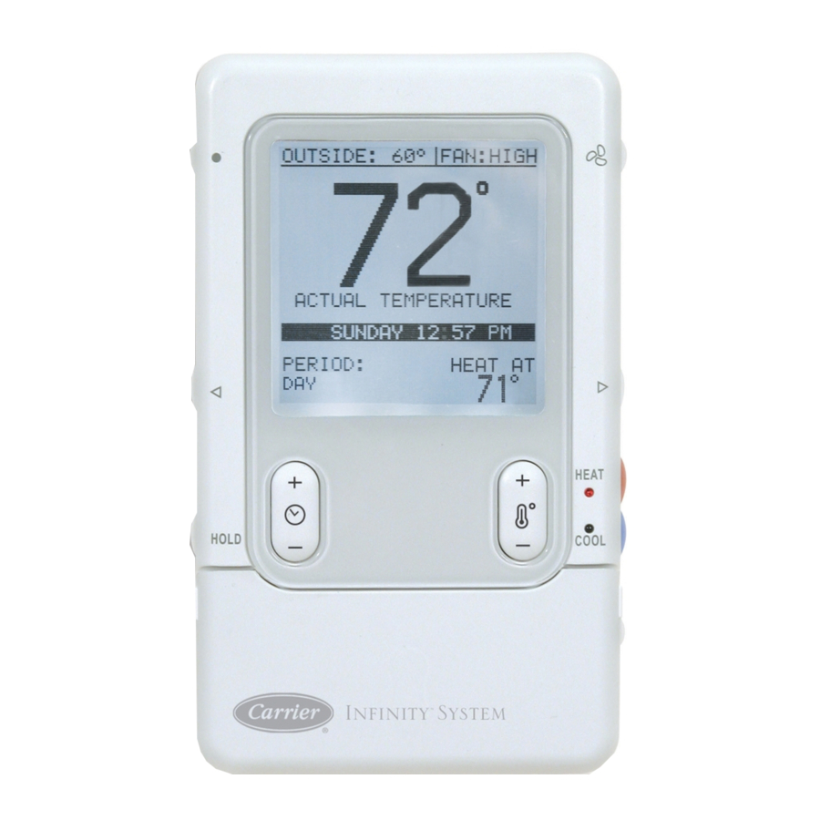
Fig. 1 - - Infinityt Zone Control
Installation Instructions
HEAT
COOL
OFF
S
™
YSTEM
A04031
NOTE: Read the entire instruction manual before starting the
installation.
TABLE OF CONTENTS
. . . . . . . . . . . . . . . . . . . . . . . . . . . . . . . . . . .
. . . . . . . . . . . . . . . . . . . . . . . . . . . . . . . . . . . .
. . . . . . . . . . . . . . . . . . . . . . . . . . . . . . . .
. . . . . . . . . . . . . . . . . . . . . . . . . . . . . . . . . . . . .
. . . . . . . . . . . . . . . . . . . . . . . . . . . . . . . . . . . .
. . . . . . . . . . . . . . . . . . . . . . . . . . . . . . . . . . . . . .
. . . . . . . . . . . . . . . . . . . . . . . . . . . . . . .
. . . . . . . . . . . . . . . . . . . . . . . . . . . . . . . . . .
. . . . . . . . . . . . . . . . . . . . . . . . . . . . . .
SAFETY CONSIDERATIONS
Read and follow manufacturer instructions carefully. Follow all
local electrical codes during installation. All wiring must conform
to local and national electrical codes. Improper wiring or
installation may damage the Infinity Zone System.
Recognize safety information. This is the safety- -alert symbol
When you see this symbol on the equipment and in the instruction
manual, be alert to the potential for personal injury. Understand the
signal words DANGER, WARNING, and CAUTION.
These words are used with the safety- -alert symbol. DANGER
identifies the most serious hazards, which will result in severe
personal injury or death. WARNING signifies a hazard, which
could result in personal injury or death. CAUTION is used to
identify unsafe practices, which may result in minor personal
injury or product and property damage. NOTE is used to highlight
suggestions which will result in enhanced installation, reliability, or
operation.
PAGE
. . . . . . . . . . . . . . . . . . . . . . . . .
. . . . . . . . . .
. . . . . . . . . . . . . .
. . . . . . . . . . . . . . . . . . . . . . . . .
. . . . . . . . . . . . . . . . . . . . . .
. . . . . . . . . . . . . . . . . . . . .
. . . . . . . . . . . . . . . . . .
1
2
2
2
5
6
8
9
9
9
9
13
14
16
18
19
.
Advertisement
Table of Contents

Related Manuals for Carrier Infinity Control


Summary of Contents for Carrier Infinity Control
-
Page 1: Table Of Contents
SYSTXCCUIZ01-- B Infinityt Control Installation Instructions NOTE: Read the entire instruction manual before starting the installation. TABLE OF CONTENTS PAGE SAFETY CONSIDERATIONS ......INTRODUCTION . -
Page 2: Introduction
Infinity Damper Control Module (P/N SYSTXCC4ZC01) allows is easily accessible and visible to the adult homeowner or end user. connection of a Carrier HRV or ERV without the need for a For accurate temperature measurement, the following guidelines separate wall control. -
Page 3: Wiring Considerations
CAUTION Damper Control Damper Control Module Module ZS_C ELECTRICAL OPERATION HAZARD Failure to follow this caution may result in equipment damage or improper operation. Sensor 1 Sensor 2 To prevent possible damage to the Damper Control Module, DO NOT mount on plenum, ductwork, or flush against furnace or fan coil. - Page 4 Recessed terminal block in wall 1 " (38.1 mm) wide by 2 " (54 mm) high Recessed Mount Interlocking Tabs (4) A03186 A07150 Fig. 4 - - Recessed Mount Backplate Fig. 7 - - Recessed Mount Assembly Surface Mount Backplate to wall Interlocking Tabs (4) A03191 A03187...
-
Page 5: Installing Infinity Zone Control
INSTALLING INFINITY ZONE CONTROL Indoor Unit Zone Control User Interface & WARNING Smart Sensor(s) Green Yellow A B C D ELECTRICAL SHOCK HAZARD White Failure to follow this warning could result in personal injury or death. 1-Stage AC A B C D A B C D Before installing Infinity Zone Control, turn off all power to Humidifier... -
Page 6: Initial Power- -Up
CAUTION CAUTION ELECTRICAL OPERATION HAZARD EQUIPMENT HAZARD Failure to follow this caution may result in equipment damage Failure to follow this caution may result in equipment damage. or improper operation. Do not apply 24VAC fan powered humidifier (with internal Improper wiring of the ABCD connector will cause the power supply) direct to indoor unit HUM and COM terminals. - Page 7 Hydronic Heat Applications NOTE: If the variable- -speed indoor equipment (furnace or fan coil) cannot be found, the User Interface will display “CANNOT The - -B model of the Infinity Zone Control supports Hydronic COMMUNICATE WITH INDOOR UNIT”. This MUST be Heat applications in the form of a hot water coil on FE fan coils corrected before the initial power up sequence can continue.
-
Page 8: Quick Start
zones. When finished, press right- -side button to continue. See Fig. Assessment will measure the relative size of the ductwork, up and through the dampers. These measurements are used to control the correct amount of airflow in the zoned system. Status messages ZONING ZONING will appear on the screen to indicate what the system is doing. -
Page 9: Install / Service Menus
EQUIPMENT SUMMARY MENU NOTE: Override time will not appear if programming has been turned off. EQUIPMENT SUMMARY 4. You can change the temporary override time in 15- -minute FURNACE 58MVB0100-12 increments by pressing the TIME (+/- -) button until the de- 24ANA136A003 sired override time is selected, or press the HOLD button FILTER... - Page 10 Offsets: S EFFICIENCY - - fixed airflow used to achieve specified ratings - - This option allows calibration (or deliberate miscalibration) of the no dehumidification airflow reduction. This is nominally 350 temperature and humidity sensors. These offsets are added to the CFM/ton, but will vary if a 2- -stage outdoor unit is used.
-
Page 11: Setup - Fan Coil
Outside temperature above which the electric heat will not operate except for defrost. G Terminal This setup option selects desired operation when the R- -G circuit is made on the fan coil control board. S DISABLED (Default) FE Fan Coil or S FAN - - turns on fan to selected fan speed when G terminal is Variable Speed Furnace energized. - Page 12 Setup - - Hydronic Heat from 20 to 50_F / - -7 to 10_C are available in 5_ increments. Setup - - Hybrid Heat HYDRONIC HEAT SETUP HOT WATER LOCKOUT: > 30 F HYBRID HEAT SETUP HEAT PUMP OUTSIDE LOCKOUT TEMPS LOCKOUT: <...
-
Page 13: Checkout Menus
CHECKOUT MENUS HUMIDIFY WITH FAN (Heating Mode Only): S NO (default) S YES CHECKOUT FURNACE If YES, the humidifier will turn on if there is a humidify demand HEAT PUMP HEATING present. The fan will turn on to Low speed if the fan setting is HEAT PUMP COOLING Auto. -
Page 14: Service Menus
NOTE: Airflows during Checkout modes are fixed to the NOTE: Selecting a lower airflow noise limit may decrease the Efficiency setting and are independent of other airflow settings. To homeowner’s comfort in that zone. view airflows for normal heat pump heating mode, exit the Sensor Types: Checkout screen and apply a heating demand to the system. - Page 15 high static pressure by cutting back blower RPM. Static Press: S Calculated static pressure of indoor unit. Lockout Timer: S If static pressure cannot be accurately calculated, the display will S Seconds read UNKNOWN. When this is seen, the system is adjusting to If a lockout timer is active, this will show the current time value.
-
Page 16: Operational Information
Staging Timer entered every time prior to viewing “LAST 10 SYSTEM EVENTS” section. In multistage heating or cooling, this timer prevents any higher Service - - Model / Serial Numbers stage from turning on until the preceding stage has been on for 10 minutes. - Page 17 Unoccupied c. If shut down occurs, other zones need to call before equipment will resume operation. Pressing the HOLD button for 3 seconds will set the selected zone Dehumidify Operation to unoccupied status. A zone may also be programmed to be unoccupied in any period of the schedule.
-
Page 18: Troubleshooting
TROUBLESHOOTING Please refer to the Troubleshooting Guide available on HVAC Partners for more detail. Infinity Zone Control does not power up. 1. Recheck wiring to ABCD on all devices. 2. Make sure all colors match for every terminal. 3. Make sure power is applied to the indoor unit, and the amber LED is lit on indoor control circuit board. 4. -
Page 19: System Malfunction Screen
SYSTEM MALFUNCTION SCREEN Outdoor Unit The code number represents flash code on circuit board of outdoor OUTSIDE: 84_ | FAN: AUTO unit. Code 45 - - Control Failure Code 47 - - No 230V at unit Code 73 - - Contactor shorted Code 74 - - No high voltage at compressor HVAC SERVICE 1--- 800--- 555--- 1212... - Page 20 Catalog No: UIZ01---4SI Copyright 2008 Carrier Corp. S 7310 W. Morris St. S Indianapolis, IN 46231 Printed in China Edition Date: 03/08 Manufacturer reserves the right to change, at any time, specifications and designs without notice and without obligations. Replaces: UIZ01--- 3SI...
Need help?
Do you have a question about the Infinity Control and is the answer not in the manual?
Questions and answers