Advertisement
Quick Links
Visit www.carrier.com
Installation and Operating Instructions
NOTE: Read the entire instruction manual before starting the
installation.
This symbol → indicates a change since the last issue.
SAFETY CONSIDERATIONS
Read and follow manufacturer instructions carefully. Follow all
local electrical codes during installation. All wiring must conform
to local and national electrical codes. Improper wiring or installa-
tion may damage thermostat.
Recognize safety information. This is the safety-alert symbol
When you see this symbol on the equipment and in the instruction
manual, be alert to the potential for personal injury.
Understand the signal words DANGER, WARNING, and CAU-
TION. These words are used with the safety-alert symbol.
DANGER identifies the most serious hazards which will result
in severe personal injury or death. WARNING signifies a hazard
which could result in personal injury or death. CAUTION is used
to identify unsafe practices which would result in minor personal
injury or product and property damage. NOTE is used to highlight
suggestions which may result in enhanced installation, reliability,
or operation.
INTRODUCTION
Carrier thermostats are wall-mounted, low-voltage thermostats
which maintain room temperature by controlling the operation of
a heating and air conditioning system. Separate heating and
cooling setpoints, plus auto changeover provide maximum comfort
and flexibility. Batteries are optional; temperature and mode
settings are preserved with the power off.
INSTALLATION CONSIDERATIONS
Power
Note that all thermostats are dual powered where batteries can be
installed or in the presence of R and C (24vac) are not required. 2
AA batteries are furnished with the product.
Models
There are 3 different models. The 9th and 10th letters of the part
number indicate the model. These 2 letters also appear on the
package and on the circuit board. Be sure to have the proper
thermostat for the intended application. Models are:
AC — 1-stage cool, 1-stage heat for AC systems only.
HP — 1-stage cool, 2-stage heat for either HP, or AC with 2-stage
heat.
2S — 2-stage cool, 2-stage heat for 2-speed AC systems, or
2-stage cool, 3-stage heat for 2-speed HP systems.
Use each only for its intended purpose. See Table 1.
INSTALLATION
Step 1—Thermostat Location
Thermostat should be mounted:
• Approximately 5 ft. (1.5m) from floor.
• Close to or in a frequently used room, preferably on an inside
partitioning wall.
Manufacturer reserves the right to discontinue, or change at any time, specifications or designs without notice and without incurring obligations.
Book
PC 101
Tab
Catalog No. 03TS-TA54
Non-Programmable Thermostat
.
Printed in U.S.A.
Form TSTAT-30SI
TSTATCCN(AC,HP,2S)01-C
TSTATCCNAC01-C
TSTATCCNHP01-C
TSTATCCN2S01-C
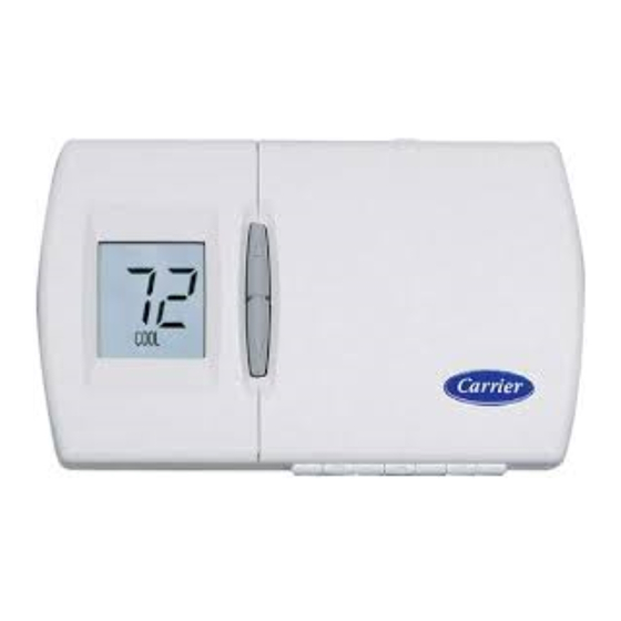
HEIGHT (IN.)
WIDTH (IN.)
3-1/2
Fig. 1—Carrier Non-Programmable Thermostat
• On a section of wall without pipes or duct work.
Thermostat should NOT be mounted:
• Close to a window, on an outside wall, or next to a door leading
to the outside.
• Exposed to direct light and heat from a lamp, sun, fireplace, or
other temperature-radiating object which may cause a false
reading.
• Close to or in direct airflow from supply registers and return-air
grilles.
• In areas with poor air circulation, such as behind a door or in
an alcove.
Step 2—Select Model
AC Model (1-stage cool, 1-stage heat) is to be used for single-
stage heating and/or cooling applications only. It CANNOT be
used with optional outdoor temperature sensor. (See Table 1.)
HP Model (1-stage cool, 2-stage heat) can be used with a
single-speed heat pump (HP), or an air conditioner (AC) with a
2-stage furnace or fan coil. Software Option 5 selects HP/AC
operation. This thermostat comes configured from the factory as a
heat pump thermostat. Select AC in software Option 5 for AC
operation. When AC operation is selected, the O/W2 terminal is
converted from a reversing valve output (O) to a second-stage heat
output (W2). This output can be used to control 2-stage furnaces or
2-stage electric heat in fan coils. (See Table 1.)
2S Model is for 2-speed compressor systems only (HP and AC).
Output Y1 controls compressor low speed and output Y/Y2
controls compressor high speed. (See Table 1.)
Pg 1
A04103
DEPTH (IN.)
5-3/4
1-3/8
08-04
Replaces: New
Advertisement

Subscribe to Our Youtube Channel
Related Manuals for Carrier TSTATCCNAC01-C


Summary of Contents for Carrier TSTATCCNAC01-C
- Page 1 • On a section of wall without pipes or duct work. INTRODUCTION Thermostat should NOT be mounted: Carrier thermostats are wall-mounted, low-voltage thermostats • Close to a window, on an outside wall, or next to a door leading which maintain room temperature by controlling the operation of to the outside.
-
Page 2: Electrical Shock Hazard
Table 1—Model Selection and Wiring Diagram Chart AIR CONDITIONER HEAT PUMP OUTDOOR UNIT 1 Speed 2 Speed 1 Speed 2 Speed 1-Stage Model AC Model 2S Requires Requires Furnace See Fig. 2 See Fig. 8 Dual Fuel Thermostat Dual Fuel Thermostat 2-Stage Model AC Model HP... - Page 3 An explanation for each of these and how to enter the configura- 5. Press MODE button again to return to Option 02. The SET tion mode follows. icon will now be off. To enter the configuration mode: 6. Use up and down buttons to select another Option, or press FAN button to exit configuration mode.
- Page 4 mode, cooling will not be initiated if the outdoor air temperature is OPTION 10 — O (REVERSING VALVE) ON WITH HEAT OR below 55° F. If the compressor is already operating and the COOL SELECTION outdoor air temperature drops below 55° F., the compressor will This selection is only available on HP and 2S model thermostats continue to operate until the cooling cycle has completed.
- Page 5 5. Press MODE button again to return to Option 15. The SET TO SELECT: icon will now be off. 1. Enter configuration mode (if not already there). 6. Use up and down buttons to select another Option, or press 2. Use up and down buttons to display Option 21. The SET icon FAN button to exit configuration mode.
-
Page 6: Wiring Diagram Notes
W/W1 Y/Y2 O/W2/B Model Numbers: TSTATCCNAC01-C, TSTATCCNHP01-C, TSTATCCN2S01-C Note: AC = Air Conditioner, HP = Heat Pump, 2S = 2-Speed, N/A = Not Applicable 3. Put away tools and instruments, and clean up debris. 4. Review Homeowner’s Guide with owner. - Page 7 SINGLE-STAGE MODEL AC 01-C SINGLE-SPEED TWO-STAGE OR THERMOSTAT FURNACE AIR CONDITIONER MODEL AC 01-C SINGLE-SPEED VARIABLE-SPEED THERMOSTAT FURNACE AIR CONDITIONER 24 VAC HOT 24 VAC HOT 24 VAC COMM 24 VAC COMM HEAT STAGE 1 W/W1 HEAT STAGE 1 W/W1 W/W1 COOL STAGE 1 Y/Y2...
- Page 8 MODEL HP 01-C TYPICAL SINGLE-SPEED TYPICAL MODEL HP 01-C SINGLE-SPEED THERMOSTAT FAN COIL AIR CONDITIONER FAN COIL THERMOSTAT HEAT PUMP 24 VAC HOT 24 VAC HOT 24 VAC COMM 24 VAC COMM HEAT STAGE 1 W/W1 COOL STAGE 1 Y/Y2 COOL/ HEAT Y/Y2 STAGE 1...
- Page 9 MODEL 2S 01-C TYPICAL TWO-SPEED MODEL 2S 01-c TYPICAL TWO-SPEED THERMOSTAT FAN COIL AIR CONDITIONER THERMOSTAT FAN COIL HEAT PUMP 24 VAC HOT 24 VAC HOT 24 VAC COMM 24 VAC COMM HEAT STAGE 1 W/W1 COOL STAGE 2 COOL/HEAT Y/Y2 Y/Y2 STAGE 2...
- Page 10 MODEL 2S EASY SELECT TWO-SPEED MODEL HP EASY SELECT SINGLE-SPEED THERMOSTAT TERMINAL BOARD AIR CONDITIONER THERMOSTAT TERMINAL BOARD HEAT PUMP J1 JUMPER J1 JUMPER 24 VOLT HOT 24 VAC HOT 24 VOLT COMM 24 VAC COMM COOL STAGE 2 Y/Y2 Y/Y2 COOL/HEAT Y/Y2...
-
Page 11: Operational Information
OPERATIONAL INFORMATION Five-minute Compressor Timeguard This timer prevents the compressor from starting unless it has been off for at least 5 minutes. It can be defeated for 1 cycle by simultaneously pressing the FAN mode button and the INCREASE TEMPERATURE button. Fifteen-minute Cycle Timer This timer prevents the start of a heating or cooling cycle until at least 15 minutes after the last start of the same cycle. - Page 12 A04105 Keypad lockout (Off or On: Default = Off) Copyright 2004 CARRIER Corp. • 7310 W. Morris St. • Indianapolis, IN 46231 tstat-30si Manufacturer reserves the right to discontinue, or change at any time, specifications or designs without notice and without incurring obligations.
Need help?
Do you have a question about the TSTATCCNAC01-C and is the answer not in the manual?
Questions and answers