Table of Contents
Advertisement
Advertisement
Table of Contents

Related Manuals for HP ProCurve 10Base-T 12


Summary of Contents for HP ProCurve 10Base-T 12
- Page 1 HP ProCurve 10Base-T Hubs Installation Guide HP 10Base-T Hub 12 HP 10Base-T Hub 12M HP 10Base-T Hub 24 HP 10Base-T Hub 24M For world-wide support on all HP Network Connectivity Products visit our web site at: http://www.hp.com/go/procurve Less Work, More Network...
- Page 3 HP ProCurve 10Base-T Hubs Installation Guide...
- Page 4 5967-6861 performance, or use of this material. June 1998 Hewlett-Packard assumes no responsibility for the use or reliability of its software on equipment that is not furnished Applicable Product by Hewlett-Packard. HP ProCurve 10Base-T Hub 12 (J3300A)
-
Page 5: Rear View
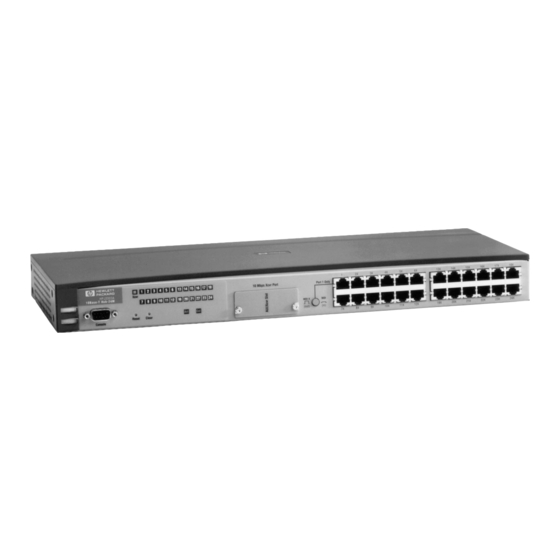
HP ProCurve 10Base-T Hubs HP ProCurve 10Base-T Hubs The HP ProCurve 10Base-T Hubs are a family of multiport repeaters. With these hubs, you can connect computers, printers, and servers together for file sharing. These hubs are compliant with the IEEE 802.3 Type 10Base-T standard and support both 802.3 and Ethernet networks. - Page 6 HP ProCurve 10Base-T Hubs The following illustrations show each of the four hubs in the HP ProCurve 10Base-T Hubs family. Port 1 Only ProCurve 10Base-T Hub 12 10 Mbps Xcvr Port Xcvr HP J3300A Power MDI-X (out) (In) Reset Fault Figure 2.
- Page 7 HP ProCurve 10Base-T Hubs Features The following tables detail information about features on the HP ProCurve 10Base-T Hubs. Feature Description The following table provides descriptive information about features on the HP ProCurve 10Base-T Hubs. Table 1. HP ProCurve 10Base-T Hub Feature Descriptions Feature Type Feature Description Network Connections •...
- Page 8 HP ProCurve 10Base-T Hubs Feature Type Feature Description • Advanced embedded SNMP agent code in both the HP J3301A and HP J3303A, enabling these hubs to be managed remotely from a network management station using SNMP over IP (using the configured IP address).
-
Page 9: Feature Comparison
HP ProCurve 10Base-T Hubs Feature Comparison The following table details what features are present on the managed and the unmanaged hubs. Table 2. Feature Comparison Between Managed and Unmanaged Hubs Feature HP J3300A/HP J3302A HP J3301A/HP J3303A (Unmanaged) (Managed) á á... -
Page 10: Factory Default Settings
HP ProCurve 10Base-T Hubs Factory Default Settings The following table details the factory defaults for all of your hub settings. Table 3. Factory Default Settings on HP ProCurve 10Base-T Hubs Feature J3300A/J3302A J3301A/J3303A Port Status Enabled Enabled MDI/MDI-X Port Status MDI-X (Button not MDI-X (Button not depressed) -
Page 11: Table Of Contents
Contents 1 Installing the Hub Installing Your Hub ......... . . 1-2 1. - Page 12 A Specifications B Cables and Connectors Straight-Through Twisted-Pair Cable for Hub-to-Computer Network Connection Twisted-Pair Straight-Through Cable ..... . B-3 Twisted-Pair Crossover Cable ......B-3 RS-232 Connector and Cable Pin-Outs .
-
Page 13: Installing The Hub
Installing the Hub This chapter describes how to install the hub. Topics in this chapter include verifying included parts installing the transceiver module verifying the hub operates correctly mounting the hub connecting the hub to your network connecting hubs together... -
Page 14: Installing Your Hub
Installing the Hub Installing Your Hub Installing Your Hub To install and configure your hub, you must complete six basic tasks. They are: locating and verifying the necessary parts installing a transceiver module connecting the hub to a power source mounting the hub connecting the hub to your network 1. -
Page 15: Verify The Hub Operates Correctly
Installing the Hub Installing Your Hub external transceiver). Because of these widths, clearance in front of your hub may be a factor in the placement of the device or stack that contains protruding transceiver connectors, for example, a BNC connectors. Inspect your installation site and identify whether enough room will be available for the installed transceiver to be connected. - Page 16 Installing the Hub Installing Your Hub Check the LEDs on the hub’s front panel. When the hub is powered on, it performs a power-on self test. See the table below for the LED self test time that occurs during the self test. Note the upper number is for the HP J3300A/HP J3302A and the lower number is for the HP J3301A/HP J3303A.
-
Page 17: Mount The Hub
Installing the Hub Installing Your Hub Note that once you have connected cables to the hub, an AUI transceiver LED or twisted pair Port LED stays on if link beat has been detected at the port from an incoming device and the port is enabled. A Port LED turns off if link beat is not detected. - Page 18 Installing the Hub Installing Your Hub Using a Phillips Crosshead No. 2 screwdriver, attach the mounting brackets to the hub with No. M4 (5/16") silver screws (included in the accessory kit). Figure 1-2. Hub-to-Bracket Assembly Position the hub in the rack or cabinet and slide it up or down until the rack holes line up with the bracket holes.
-
Page 19: Wall Mounting
Installing the Hub Installing Your Hub Figure 1-3. Hub-to-Rack Assembly Wall Mounting Using a Phillips (crosshead) No. 2 screwdriver, attach the mounting brackets to the hub with 8-mm (approximately 5/16") M4 screws included in the accessory kit. Then attach the hub to a wood surface (minimum 1/2-inch plywood or equivalent) with No. -
Page 20: Connect The Hub To Your Network
Installing the Hub Installing Your Hub 5. Connect the hub to your network Connect the hub to an AC power source. With the hub mounted, you are now ready to connect the hub to your network. Typical hub connections are: hub-to-device connections. -
Page 21: Connecting Hubs Together
Installing the Hub Installing Your Hub Connecting Hubs Together Twisted-Pair Cascade Connections To expand your network, the hub can be connected to other hubs with straight- through cable by using the Media Dependent Interface (MDI/MDI-X) switch. The MDI/MDI-X switch controls how the signals are sent through the twisted- pair cable connected to Port 1. - Page 22 Installing the Hub Installing Your Hub In the following illustration, the top hub in the stack is connected to two end nodes and to a second hub. Note the second hub shows Port 1 connecting to a PC, using a straight through twisted pair cable with the port in the MDI-X position.
-
Page 23: Thinlan Connections
Installing the Hub Installing Your Hub ThinLAN Connections With an HP ThinLAN Transceiver Module for 10Base2 networks installed in the transceiver slot, you can connect your hub or a stack of hubs to a 10Base- 2 ThinLAN network. The following illustration shows a hub with an HP ThinLAN Transceiver. -
Page 24: Connecting The Hp Procurve 10Base-T Hubs To A Fiber-Optic Backbone
Installing the Hub Installing Your Hub N o t e Each ThinLAN cable segment must be terminated using a 50-ohm terminator at each end. In the illustration above, a 50-ohm terminator is placed at each end of the cable segment. Connecting the HP ProCurve 10Base-T Hubs to a Fiber-Optic Backbone With a Fiber-Optic transceiver for 10Base-FL networks, you can connect your... -
Page 25: Troubleshooting
Troubleshooting This chapter describes ways to troubleshoot the hub. Topics covered are: troubleshooting approaches using a checklist to diagnose the hub diagnosing with the LEDs hub maintenance tasks Troubleshooting Approaches You can diagnose problems on all HP ProCurve 10Base-T Hubs by checking the LEDs on the front of the hub as described in the section, “Diagnosing with the LEDs”... -
Page 26: Diagnosing With The Leds
Troubleshooting Diagnosing with the LEDs Use the following table to diagnose the problem with your HP ProCurve 10Base-T Hub. Problem Solution How do I reset the hub? You can reset the hub three five different ways: • From the device, remove the plug on the power cord from the power source or the hub and reconnect it. -
Page 27: Interpreting Led Status
Troubleshooting Most problems with the hub can be diagnosed using the LEDs on its front panel. The following section describes the normal LED pattern during self- test, and LED patterns that indicate error conditions on the hub. Interpreting LED Status Two types of LEDs exist on the hub. -
Page 28: Interpreting Port Status Leds
Troubleshooting Interpreting Port Status LEDs The following table provides LED port information for the HP J3301A and the HP J3303A. Color Meaning of LED Twisted-pair Green On indicates Link Beat is detected from the attached node and Ports the port is enabled on the HP J3301A and HP J3303A. Off indicates the port is not receiving the link beat signal from the attached node. -
Page 29: Led Operation
Troubleshooting LED Operation The tables on the following pages list the hub’s LEDs, their possible states, and diagnostic tips to resolve any error conditions. LED patterns indicating problems Diagnostic Tips Power Coll Port LED Fault Check cabling on the indicated port all the way out to the device attached to that port. -
Page 30: Hub Maintenance Tasks
Troubleshooting Hub Maintenance Tasks There are several hub maintenance tasks you can perform. They include: testing the hub only clearing a password from the ASCII console running connectivity tests Each of these tasks is described in the following sections. Testing the Hub Only If you believe that the hub is not operating correctly, you can test it to determine normal operation in two ways: pressing the Reset Button. -
Page 31: Running Connectivity Tests
Troubleshooting Running Connectivity Tests Both the hub and cabling can be tested by running an end-to-end communica- tions test—a test that sends known data from one network device to another through the hub—such that you can verify that the data was correctly trans- mitted between the devices. -
Page 32: Obtaining Firmware Enhancements
Troubleshooting Obtaining Firmware Enhancements In the future, Hewlett-Packard may provide improvements to the HP ProCurve 10Base-T Hub 12M and the HP ProCurve 10Base-T Hub 24M through firmware upgrades. The upgrade code can be downloaded from a PC attached to the hub’s RS-232 port or over the network. -
Page 33: Specifications
Specifications Physical Width: 42.5 cm (16.7 in) Depth: 23.8 cm (9.4 in) Height: 4.36 cm (1.7 in) Weight : 8 lbs 13 oz. (8.8 lbs) Electrical The hub automatically adjusts to any voltage between 100-127 and 200-240 volts and either 50 or 60 Hz. AC voltage: 100–127 volts 200–240 volts... - Page 34 Specifications Connectors The RJ-45 twisted-pair ports are compatible with the IEEE 802.3 Type 10Base-T standard. Electromagnetic Emissions: FCC part 15 Class A EN 55022 Class A EN 55022 Class B CISPR-22 Class A VCCI Level I Complies with Canadian EMC Class A requirements. Complies with Australia/New Zealand EMC Class A requirements.
-
Page 35: Cables And Connectors
Cables and Connectors This appendix lists cables that have been tested and verified for use with the HP ProCurve 10Base-T Hubs. The following topics are covered: overview twisted pair cable/connector pinouts RS-232 connector and cable pinouts It also includes minimum pin-out information so, if you wish to use an unlisted cable, you can verify that the cables used in your installation are correctly wired. - Page 36 N o t e Pins 1 and 2 must be a twisted pair. Pins 3 and 6 must be a twisted pair. Pins 4, 5, 7, and 8 are not used in this application, although they may be wired in the cable. N o t e Incorrectly wired cabling is the most common cause of problems for LAN communications.
-
Page 37: Twisted-Pair Straight-Through Cable
Twisted-Pair Straight-Through Cable Hub End (MDI-X) Computer or Transceiver End (MDI) Signal Pins Pins Signal (receive +) (transmit +) (receive –) (transmit –) (transmit +) (receive +) (transmit –) (receive –) Twisted-Pair Crossover Cable Hub End (MDI-X) Computer or Transceiver End (MDI) Signal Pins... -
Page 38: Minimum Cable Pinout For Ascii Console Connection
This appendix lists cables that have been tested and verified for use with the HP ProCurve 10Base-T Hubs. It also includes minimum pin-out information so, if you wish to use an unlisted cable, you can verify that the cables used in your installation are correctly wired. -
Page 39: C Safety And Regulatory Statements
Safety and Regulatory Statements This chapter covers the following topics: mounting precautions power precautions safety statements regulatory statements Declaration of Conformity Mounting Precautions When you put a hub into a rack, follow these mounting precautions: The rack or cabinet should be adequately secured to prevent it from becoming unstable and/or falling over. -
Page 40: Power Precautions
N o t e If your installation requires a different power cord than the one supplied with the hub, be sure to use a power cord displaying the mark of the safety agency that defines the regulations for power cords in your country. The mark is your assurance that the power cord can be used safely with the hub. -
Page 41: Safety Information
Safety and Regulatory Statements Safety Information Safety Information Documentation reference symbol. If the product is marked with this symbol, refer to the product documentation to get more information about the product. WARNING A WARNING in the manual denotes a hazard that can cause injury or death. -
Page 42: Informations Concernant La Sécurité
Safety and Regulatory Statements Informations concernant la sécurité Informations concernant la sécurité Symbole de référence à la documentation. Si le produit est marqué de ce symbole, reportez-vous à la documentation du produit afin d'obtenir des informations plus détaillées. WARNING Dans la documentation, un WARNING indique un danger susceptible d'entraîner des dommages corporels ou la mort. -
Page 43: Hinweise Zur Sicherheit
Safety and Regulatory Statements Hinweise zur Sicherheit Hinweise zur Sicherheit Symbol für Dokumentationsverweis. Wenn das Produkt mit diesem Symbol markiert ist, schlagen Sie bitte in der Produktdokumentation nach, um mehr Informationen über das Produkt zu erhalten. WARNING Symbol für Dokumentationsverweis. Wenn das Produkt mit diesem Symbol markiert ist, schlagen Sie bitte in der Produktdokumentation nach, um mehr Informationen über das Produkt zu erhalten. -
Page 44: Considerazioni Sulla Sicurezza
Safety and Regulatory Statements Considerazioni sulla sicurezza Considerazioni sulla sicurezza Simbolo di riferimento alla documentazione. Se il prodotto è contras- segnato da questo simbolo, fare riferimento alla documentazione sul prodotto per ulteriori informazioni su di esso. WARNING La dicitura WARNINGdenota un pericolo che può causare lesioni o morte. -
Page 45: Consideraciones Sobre Seguridad
Safety and Regulatory Statements Consideraciones sobre seguridad Consideraciones sobre seguridad Símbolo de referencia a la documentación. Si el producto va marcado con este símbolo, consultar la documentación del producto a fin de obtener mayor información sobre el producto. WARNING Una WARNING en la documentación señala un riesgo que podría resultar en lesiones o la muerte. -
Page 46: Safety Information (Japanese
Safety and Regulatory Statements Safety Information (Japanese) Safety Information (Japanese) -
Page 47: Regulatory Statements
Safety and Regulatory Statements Regulatory Statements Regulatory Statements FCC Class A Statement (for U.S.A. Only) when using unshielded cables: This equipment has been tested and found to comply with the limits for a Class A digital device, pursuant to Part 15 of the FCC Rules. These limits are designed to provide reasonable protection against harmful interference when the equipment is operated in a commercial environment. - Page 48 Safety and Regulatory Statements Regulatory Statements Korea European Community This equipment complies with ISO/IEC Guide 22 and EN55022 Class A with unshielded cables and EN55022 NoteWith unshielded cables this is a Class A product. In a domestic environment, this product may cause radio interfe ence, in which case the user may be required to take adequate measures.
- Page 49 Safety and Regulatory Statements Regulatory Statements C-11...
-
Page 51: Index
Index Numerics front of the hub status LEDs … 2-3 50-ohm terminator for a ThinLAN cable segment … 1-12 HP AdvanceStack SNMP Module LED pattern during self-test … 2-5 Activity LED … 1-4, 2-3, 2-6 AUI/Xcvr LED … 2-4 at a glance … iii connecting to fiber-optic backbone …... - Page 52 list included parts … 1-2 Security LED … 1-4 Self Test … 2-5 Self test LED pattern during … 1-4 MDI switch specifications … A-1 using … 1-9 connectors … A-2 MDI-X switch electrical … A-1 using … 1-9 electromagnetic … A-2 mounting the hub …...
- Page 54 Technical information in this document is subject to change without notice. ©Copyright Hewlett-Packard Company 1997-1998. All rights reserved. Reproduction, adaptation, or translation without prior written permission is prohibited except as allowed under the copyright laws. Printed in Singapore 6/98 Manual Part Number...
Need help?
Do you have a question about the ProCurve 10Base-T 12 and is the answer not in the manual?
Questions and answers