
Subscribe to Our Youtube Channel
Related Manuals for AMX 16-Channel Custom Panel Interface AXP-CPI16


Summary of Contents for AMX 16-Channel Custom Panel Interface AXP-CPI16
- Page 1 Operation/Reference Guide AXP-CPI16 16-Channel Custom Panel Interface Cu st o m P a n e l I n t er f a c e s L as t R e vi s ed: 1 /1 3 /20 0 9...
- Page 2 RMA number. AMX is not liable for any damages caused by its products or for the failure of its products to perform. This includes any lost profits, lost savings, incidental damages, or consequential damages. AMX is not liable for any claim made by a third party or by an AMX Dealer for a third party.
-
Page 3: Table Of Contents
Table of Contents Product Information ...1 Specifications... 1 Installation ...3 Mounting Dimensions ... 3 Setting the AXlink Device Number ... 4 Preparing/connecting captive wires ... 4 Connecting the Two 20-pin Headers ... 4 Switch Wiring Diagrams... 5 Connecting the AXlink Wiring... 5 Programming ...7 Testing the Unit ... -
Page 5: Product Information
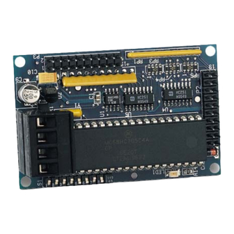
Product Information The AMX AXP-CPI16 16 Channel Custom Panel Interface Board (FIG. 1) simplifies the process of creating custom control panels for Axcess systems. Providing contact closure inputs and feedback outputs for up to 16 buttons, the miniature PC board contains a 20-pin header for ribbon cable installation or for direct mounting to a printed circuit board. - Page 6 AXP-CPI16 Specifications (Cont.) AXlink Status LED Device DIP Switch Cables Indicates AXlink communication status as follows: • One blink per second communication is functioning. • Two blinks per second devices specified in the master program do not match the specified devices found. •...
-
Page 7: Installation
Installation Mounting Dimensions AXlink AXlink PWR AXM (Component Side) (Component Side) FIG. 1 AXP-CPI16 mounting dimensions Mounting Dimensions Item Inch 0.10 2.50 1.75 44.50 L 1.55 39.40 M 2.75 69.90 2.55 64.80 0.35 8.90 0.23 5.80 0.438 11.10 0.93 23.6 AXP-CPI16 16-Channel Custom Panel Interface AXM GND Top View... -
Page 8: Setting The Axlink Device Number
As an example, the device DIP switch shown below defines device number 129 (1+128=129). Position 1 2 3 4 5 Value AMX standard device numbers are assigned as follows: Cards are 1 through 25. Boxes are 96 through 127. -
Page 9: Switch Wiring Diagrams
Switch Wiring Diagrams FIG. 2 diagrams LED and Switch wiring. LED Wiring (Typical) LED 1 LED 2 LED 3 FIG. 2 LED and switch wiring diagrams Connecting the AXlink Wiring To install the AXlink data/power bus wiring. 1. Strip 0.25 inch off the wire insulation for all four wires. If the wire is 20 AWG or less, fold the exposed wire over to obtain a positive connection. -
Page 11: Programming
Programming Use the same Axcess commands as with other AXlink control panels, such as the AXU-MSP series mini-softwire panels. When using the AXP-CPI16 as a control device, use On, Off, and Pulse commands to control sources connected to outputs and Push and Release commands to receive inputs. For additional information, refer to the Axcess Programming Language instruction manual. -
Page 12: Testing The Unit
Testing the Unit If you have programmed the Axcess software, load the program into a PC connected to the control system Master port. See Programming on page 4. 1. Push switches connected to the AXP-CPI16. 2. Look at the lower left of the Axcess screen to verify that the correct device and channel numbers are displayed. -
Page 13: Axp-Cpi16 System Worksheet
AXP-CPI16 System Worksheet Dealer ID Dealer Description Rev Number Channel 20-PIN HEADER +12 VDC PWR Pin Number Pin Number AXP-CPI16 16-Channel Custom Panel Interface Date PO Number SO Number Serial Number Device Number HEADER P2 FUNCTION AXP-CPI16 System Worksheet... - Page 14 Channel 20-PIN HEADER +12 VDC PWR Pin Number Pin Number HEADER P3 FUNCTION AXP-CPI16 16-Channel Custom Panel Interface...
- Page 16 It’s Your World - Take Control™ 3000 RESEARCH DRIVE, RICHARDSON, TX 75082 USA • 800.222.0193 • 469.624.8000 • 469-624-7153 fax • 800.932.6993 technical support • www.amx.com...
Need help?
Do you have a question about the 16-Channel Custom Panel Interface AXP-CPI16 and is the answer not in the manual?
Questions and answers