AMX AXB-DMX512 Installation Manual
Dmx512 interface
Hide thumbs
Also See for AXB-DMX512:
- Specifications (2 pages) ,
- Operation/reference manual (32 pages) ,
- Instruction manual (32 pages)
Advertisement
Quick Links
Download this manual
See also:
Instruction Manual
Overview
The AXB-DMX512 DMX512 Interface (FG5927) creates a bi-directional DMX512
AXlink connection, transmitting and receiving up to 512 DMX channels for
lighting dimmers, spotlights, and other DMX control applications.
Onboard processing and memory can create and store channel groups, faders,
patches, and up to 72 presets. A DMX lighting board can operate in tandem with
the AXB-DMX512, generate levels for storing presets, or pass through the AXB-
DMX512 for direct control of channels.
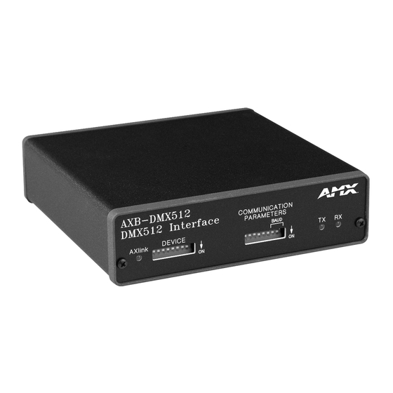
DEVICE
AXlink
ON
Device ID DIP Switch
Axlink activity LED
FIG. 1
AXB-DMX512 (front view)
Specifications
AXB-DMX512 Specifications
Power consumption
160 mA @ 12 VDC
Power supply
12 VDC
Front panel components:
LED Indicators
• AXlink LED (green and blinks to indicate AXlink
communication activity and power:
Full-Off indicates no power is being received or the
controller is not functioning properly.
One blink per second indicates power is active and
AXlink communication is functioning.
Full-On indicates there is no AXlink control or activity,
but power is On.
• RX LED (red) indicates the AXB-DMX512 is receiving
DMX512 data. Corresponds to the IN and OUT ports
on the rear panel.
• TX LED (red) indicates the AXB-DMX512 is
transmitting DMX512 data. Corresponds to the IN and
OUT ports on the rear panel.
DIP switch
• 8-position DEVICE DIP switch sets the AXlink address
(Device ID) for the AXB-DMX512.
• The DIP Switch to the right of the DEVICE DIP is
reserved - no settings are required.
Rear panel components:
DMXIN port
5-wire, captive-wire connector for receiving data.
DMXOUT port
5-wire, captive-wire connector for transmitting data.
AXlink
4-wire, captive-wire connector for data and power.
Dimensions (HWD)
1.5" x 5.5" x 5.5" (38 mm x 140 mm x 140 mm)
Enclosure
Metal with black matte finish
Mounting
Rack mounting with the optional AC-RK Accessory Rack
Kit
Weight
1.1 lb (0.5 kg)
Setting the Device DIP Switch
DEVICE
The 8-position
DIP switch on the front panel (FIG. 1) sets the AXlink
identification number for the AXB-DMX512. Make sure the device number
matches the number assigned in the Axcess software program.
The following table describes the values on the
Device DIP Switch Settings
Position
1
2
3
Value
1
2
4
TX
RX
DMX512 (Receive) LED
DMX512 (Transmit) LED
DEVICE
DIP switch.
4
5
6
7
8
8
16
32
64
128
AXB-DMX512
Terminating the Device
When using the DMX input and if this device is the last device in a chain of
DMX512 devices, you must terminate the line. To terminate the device, position
jumpers on jumper pin trios JP4 and JP5 (FIG. 2):
JP5
JP4
DEVICE DIP Switch
FIG. 2
Location of termination jumpers (JP4-JP5)
1.
Remove the jumper that is on pins 1 and 2 of jumper trios JP4 and JP5.
(Pins 1 and 2 are marked HIZ - see FIG. 3).
2.
Place the jumper on pins 2 and 3 of jumper trios JP4 and JP5. (Pins 2 and
3 are marked TERM -see FIG. 3). This terminates the incoming DMX input
with a 120 ohm resistor.
FIG. 3
Termination jumper pin settings for JP4 and JP5
Wiring Devices to the AXB-DMX512
The AXB-DMX512 has three captive-wire connectors on the rear panel (FIG. 4)
for DMX512 transmit and receive, and AXlink.
IN
FIG. 4
AXB-DMX512 (rear view)
Preparing/connecting captive wires
1.
Strip 0.25 inch of wire insulation off all wires.
2.
Insert each wire into the appropriate opening on the connector according to
the wiring diagrams and connector types described in this section. Do not
tighten the screws excessively; doing so may strip the threads and damage
the connector.
Wiring guidelines
The interface requires a 12 VDC power to operate properly. The Central
Controller supplies power via the AXlink cable or external 12 VDC power supply.
The maximum wiring distance between the Central Controller and interface is
determined by power consumption, supplied voltage, and the wire gauge used
for the cable.
Installation Guide
DMX512 Interface
Termination Jumpers
(JP4 / JP5)
The DIP Switch located to the
right of the DEVICE DIP switch
is not used - no settings are
required, and any setting
COR
will work.
front
TERM
HIZ
OUT
AXlink
Advertisement

Related Manuals for AMX AXB-DMX512


Summary of Contents for AMX AXB-DMX512
- Page 1 Onboard processing and memory can create and store channel groups, faders, patches, and up to 72 presets. A DMX lighting board can operate in tandem with the AXB-DMX512, generate levels for storing presets, or pass through the AXB- DMX512 for direct control of channels.
-
Page 2: Replacing The Lithium Battery
©2007 AMX. All rights reserved. AMX and the AMX logo are registered trademarks of AMX. AMX reserves the right to alter specifications without notice at any time. 3000 RESEARCH DRIVE, RICHARDSON, TX 75082 • 800.222.0193 • fax 469.624.7153 • technical support 800.932.6993 • www.amx.com Mounting the AXB-DMX512 in a Rack To mount the AXB-DMX512 in an equipment rack, you will need an AC-RK rack mounting kit.
Need help?
Do you have a question about the AXB-DMX512 and is the answer not in the manual?
Questions and answers