Sign In
Upload
Download
Table of Contents
Contents
Add to my manuals
Delete from my manuals
Share
URL of this page:
HTML Link:
Bookmark this page
Add
Manual will be automatically added to "My Manuals"
Print this page
×
Bookmark added
×
Added to my manuals
Manuals
Brands
Meyer Sound Manuals
Speakers
MM-4XP
Operating instructions manual
Meyer Sound MM-4XP Operating Instructions Manual
Industrial series miniature loudspeaker and power supply
Hide thumbs
1
2
3
4
Table Of Contents
5
6
7
8
9
10
11
12
13
14
15
16
17
18
19
20
21
22
23
24
25
26
27
28
29
30
31
32
page
of
32
Go
/
32
Contents
Table of Contents
Bookmarks
Table of Contents
Important Safety Instructions
Safety Summary
Table of Contents
Chapter 1: Introduction
How to Use this Manual
The MM-4XP Miniature Loudspeaker
Chapter 2: The MPS-488 Power Supply
The MPS-488 Front Panel
The MPS-488 Rear Panel
MPS-488 Current Draw
Safety Issues
Chapter 3: The MM-4XP Loudspeaker
The MM-4XP Connector
The MM-4XP LED
Connecting MM-4XP Loudspeakers to the MPS-488
Chapter 4: Mounting the MM-4XP
Important Safety Considerations
Mounting the MM-4XP with the MUB-MM4XP U-Bracket
Appendix A: Specifications
MM-4XP Specifications
MPS-488 Specifications
Appendix B: MM-4XP Accessories
MM-4XP Accessories
MM-4XP Cable Connectors and Adapters
MM-4XP Cables
Appendix C: MM-4XP Cable Assembly
Assembling EN3-To-Phoenix Loudspeaker Cables
Assembling EN3-To-EN3 Loudspeaker Cables
Advertisement
Quick Links
1
The Mps-488 Front Panel
2
Chapter 2: The Mps-488 Power Supply
3
The Mps-488 Rear Panel
4
The MM-4Xp Connector
5
MM-4Xp Specifications
6
Mps-488 Specifications
Download this manual
OPERATING INSTRUCTIONS
INDUSTRIAL SERIES
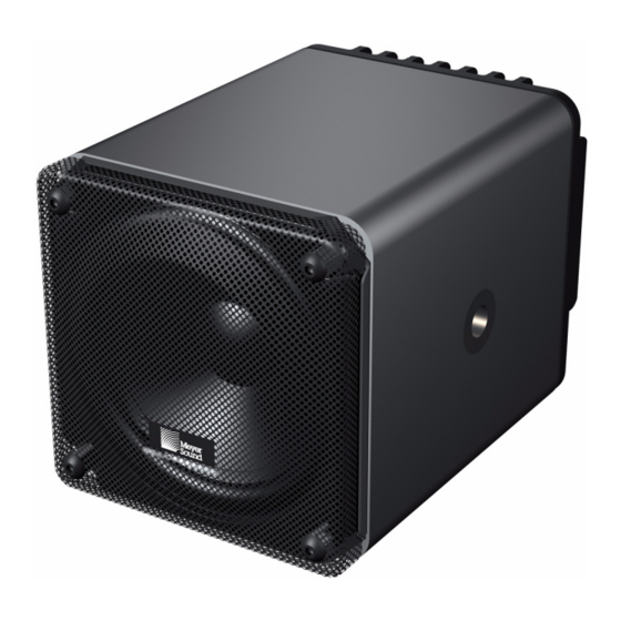
MM-4XP Miniature Loudspeaker
MPS-488 Power Supply
Keep these important operating instructions.
Check www.meyersound.com for updates.
Table of
Contents
Previous
Page
Next
Page
1
2
3
4
5
Advertisement
Table of Contents
Need help?
Do you have a question about the MM-4XP and is the answer not in the manual?
Ask a question
Questions and answers
Related Manuals for Meyer Sound MM-4XP
Speakers Meyer Sound HMS-10 Operating Installations
Surround loudspeaker mps-488 power supply (32 pages)
Speakers Meyer Sound MM-4 Datasheet
Industrial series miniature wide-range loudspeaker (2 pages)
Speakers Meyer Sound MM-4CEU Operating Instructions Manual
Industrial series miniature wide-range loudspeaker & control electronics unit (24 pages)
Speakers Meyer Sound M SERIES Operating Instructions Manual
M series compact curvilinear array loudspeaker and compact subwoofer (40 pages)
Speakers Meyer Sound QUICKFLY M Series Assembly Manual
Rigging grids and accessories (24 pages)
Speakers Meyer Sound M3D-SUB Manual
M series (48 pages)
Speakers Meyer Sound M SERIES Operating Instructions Manual
Compact high-power expanded coverage curvilinear array loudspeaker (44 pages)
Speakers Meyer Sound M Series Assembly Manual
(32 pages)
Speakers Meyer Sound MSL-10A Operating Instructions Manual
Loudspeaker (6 pages)
Speakers Meyer Sound Mina Operating Instructions Manual
M series compact curvilinear array loudspeaker (52 pages)
Speakers Meyer Sound MILO 60 Operating Instructions Addendum
High-power narrow coverage curvilinear array loudspeaker m series (16 pages)
Speakers Meyer Sound MILO 120 Operating Instructions Manual
High-power expanded coverage curvilinear array loudspeaker m series (48 pages)
Speakers Meyer Sound MTS-4 Operating Instructions Manual
Self-powered full-range loudspeaker (14 pages)
Speakers Meyer Sound UltraCompact High-Power Curvilinear Array Loudspeaker M'elodie Operating Instructions Manual
M series ultracompact high-power curvilinear array loudspeaker (44 pages)
Speakers Meyer Sound MILO Operating Instructions Manual
High-power curvilinear array loudspeaker (40 pages)
Speakers Meyer Sound LEO Series Assembly Manual
Multipurpose grid (96 pages)
This manual is also suitable for:
Mps-488
Mps-488p
Mps-488e
Table of Contents
Print
Rename the bookmark
Delete bookmark?
Delete from my manuals?
Login
Sign In
OR
Sign in with Facebook
Sign in with Google
Upload manual
Upload from disk
Upload from URL


Need help?
Do you have a question about the MM-4XP and is the answer not in the manual?
Questions and answers