
Related Manuals for Meyer Sound MILO


Summary of Contents for Meyer Sound MILO
-
Page 1: Operating Instructions
M SERIES OPERATING INSTRUCTIONS MILO High-Power Curvilinear Array Loudspeaker Keep these important operating instructions. Check www.meyersound.com for updates. - Page 2 Meyer Sound. MILO, TruPower, RMS and REM are trademarks of Meyer Sound. Meyer Sound, Meyer Sound MAPP Online, SIM and QuickFly are registered trademarks of Meyer Sound Laboratories Inc.
-
Page 3: Important Safety Instructions
2. Keep these instructions. 12. Use only with the caster rails or rigging specified by 3. Heed all warnings. Meyer Sound, or sold with the loudspeaker. Handles 4. Follow all instructions. are for carrying only. 5. Do not use this loudspeaker near water. -
Page 4: Safety Summary
Vuelva a conectar la alimentacion without using weather protection par du personnel qualifié et agréé de voltaje una vez efectuadas equipment from Meyer Sound. par le constructeur. todas las interconexiones de Do not allow water or any señalizacion de audio. -
Page 5: Table Of Contents
Wink LED (green) Reset Button Activity LED (Green) User Interface CHAPTER 4: Line Arrays and System Integration How Line Arrays Work The MILO Curvilinear Array High Frequencies Mid to Low Frequencies Adjusting Line Array Coverage High-Frequency Design Strategies Low-Frequency Design Strategies... - Page 6 APPENDIX A: Amplifier Replacement and Weather Protection Using the Rain Hood (Weather-Protected Loudspeakers) Removing and Replacing the HP-4/MILO Amplifier Replacing the HP-4/MILO Amplifier Removing and Replacing the HP-4/MILO Amplifier (Weather- Protected Version) Replacing the HP-4/MILO Amplifier and Rain Hood APPENDIX B MILO Specifications...
-
Page 7: Introduction
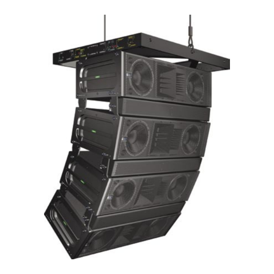
Meyer Sound’s M Series. Compact and lightweight for a self-contained, self-powered four-way system, MILO produces a robust peak output of 140 dB SPL Figure i.2: MILO is easily deployed with other members of the M Series with exceptionally flat phase and frequency response. family. -
Page 8: Integrated Amplifier And Processing
– often eliminating the need for a pullback strap in flown configurations. If circumstances dictate an acute array curve, then a PBF-MILO pull back frame can be attached to the lowest cabinet. NOTE:... -
Page 9: Advanced M Series Technology
The MG-3D/M grid allows In size and weight, MILO fits into the M Series between multipoint support and bridles. Ground stacks of up to six the M3D and the M2D; in output power and operating MILOs (or the equivalent height of MILOs and M3D-Subs) frequency range, it scales more closely to the M3D. - Page 10 INTRODUCTION...
-
Page 11: Chapter 1: Power Requirements
V AC (typically there will be 120 V AC from Line to Ground in the above example). AC POWER MILO uses a NEMA L6-20P, an IEC 309 male power When AC power is applied to the MILO loudspeaker, connector or a multipin VEAM connector and complies with the Intelligent AC power supply automatically selects worldwide product safety standards. -
Page 12: Current Requirements
32 A pk 16 A pk 37 A pk If MILO shuts down due to either low or high voltage, its term peak power supply automatically turns on again after three seconds if the voltage has returned to either normal operating window. -
Page 13: Power Connector Wiring Conventions
(brown) POWER CONNECTOR WIRING CONVENTIONS ground (green/yellow) The MILO loudspeaker requires a grounded outlet. It is very important that the system be properly grounded in order to operate safely and properly. Figures 1.2, 1.3, and 1.4 illustrate correct wiring for the creation of power cables and neutral (blue) distribution systems. -
Page 14: Electrical Safety Issues
Always use a grounded outlet and plug. TIP: Use the ring located in the rear to the side of the amplifier on the MILO loudspeaker to provide strain relief for power and signal cables. Do not use this ring for any other purpose. -
Page 15: Chapter 2: Amplification And Audio
The input impedance signals to bleed to ground. Use standard audio cables for a single MILO loudspeaker is 10 kOhms: if n represents with XLR connectors for balanced signal sources. Make the number of MILO loudspeakers in an array, paralleling... -
Page 16: Amplification And Protection Circuitry
MILO INTERCONNECTIONS A ring/stud fitting is provided on the rear of the MILO Each front 4-ohm, 12-inch, low-frequency cone driver is loudspeaker to act as a strain relief for cabling. Using this... -
Page 17: The Trupower™ Limiting System
Low- and Mid-Frequency Limiters CAUTION: The strain relief stud fitting must MILO’s left and right 12-inch cone drivers are powered by be used only to secure system cabling. This separate amplifier channels, each with a power detector fitting is not intended to be used with system rigging but routed to one limiter;... -
Page 18: Fans And Cooling System
High source levels for a prolonged period Accumulation of dust along the cooling path MILO uses a forced-air cooling system with four fans to prevent the amplifier modules from overheating. The fans The secondary fans turn off when the temperature draw air in through ducts on the front of the cabinet, over decreases to 68˚... -
Page 19: Chapter 3: Rms Remote Monitoring System
CHAPTER 3 CHAPTER 3: RMS REMOTE MONITORING SYSTEM MILO is RMS-ready and fitted standard with an RMS communication board installed in its HP-4/MILO amplifier. RMS is a real-time monitoring system that connects Meyer Sound self-powered loudspeakers with a Windows-based PC at the sound mix position or other location. Optional RMS software delivers extensive status and system performance data from every installed loudspeaker. -
Page 20: Service Button
Figure 3.3 are used exclusively by RMS, and have no effect on the acoustical and/or electrical activity of the MILO loudspeaker itself – unless MUTE or SOLO is enabled at the board and from the RMS software. -
Page 21: Chapter 4: Line Arrays And System Integration
The number of array elements, however, is directivity in a MILO line array system. To achieve optimal important: the more MILO loudspeakers used, the narrower results, it’s critical to understand how these components the vertical beamwidth becomes, as illustrated by Figure work together. -
Page 22: Adjusting Line Array Coverage
In the near- to mid-field, larger Regardless of the needs of your system design, fine-tuning splay angles increase vertical coverage. coverage for a single MILO array will be dependent on three factors: Low-Frequency Design Strategies Number of Array Elements. Determining the number... -
Page 23: Low-Frequency Strategies
Figures 4.2 shows a series of MAPP Online predictions the correction needed is usually proportional to the distance based on an example MILO system design. In this case, and high frequency air absorption. small vertical splay angles on the upper part of the array... -
Page 24: Using Milo With Subwoofers
M3D-Subs should not be placed farther back than MILO loudspeakers. However, an M3D-Sub array can MILO and the M3D-Sub be placed up to 4 feet in front of MILO loudspeaker array The M3D-Sub directional subwoofer, shown in Figure 5.5, and remain in phase. -
Page 25: Adding A Ld-1A/Ld-2 Line Driver
Similarly, when M3D-Subs are stacked on the floor below M3D-Sub’s output when co-planar and in close-proximity. your MILO array, they may be several feet closer than the Since an M3D-Sub rolls off rapidly after 80 Hz, there is no MILO array through most of the coverage, keeping them in need to engage the polarity reversal on the sub’s output. -
Page 26: Milo And The 650-P Subwoofer
MILO loudspeaker and 650-P subwoofer (when co- Sound 650-P subwoofers. The 650-P subwoofer extends planar) in phase with a minimal area of overlap; the MILO the MILO system frequency response down to 30 Hz; MILO loudspeakers in the array receive their signal following a... -
Page 27: Digital Signal Processors
The LD-3 features high-quality high-pass and low-pass conditions all come into play, measurement filters to help integrate MILO and other M Series curvilinear and correction tools are a must. Meyer’s SIM line arrays with Meyer Sound subwoofers. These filters, measurement system, the CP-10 parametric along with the LD-3’s dedicated sub section, will optimize... - Page 28 As its name indicates, MAPP Online is an online application: when a prediction is requested, data is sent over the Internet to a high-powered server at Meyer Sound that runs a sophisticated acoustical prediction algorithm using high-resolution, complex (magnitude and phase) polar data.
-
Page 29: Chapter 5: Sim® System
(time) domain information. Underwater acoustics Source Independent Measurement Technique SIM implements the Meyer Sound source independent measurement technique, a dual-channel method that accommodates statistically unpredictable excitation signals. Any excitation signal that encompasses the frequency range of interest (even intermittently) may be used to obtain highly accurate measurements of acoustical or electronic systems. - Page 30 CHAPTER 5...
-
Page 31: Appendix A: Amplifier Replacement And Weather Protection
PROTECTED LOUDSPEAKERS) AMPLIFIER If your MILO loudspeaker was ordered with optional If you need to remove the HP-4/MILO amplifier from a MILO weather protection, a rain hood is installed on the MILO loudspeaker, perform the following steps: loudspeaker. It is provided to protect the loudspeaker’s 1. -
Page 32: Replacing The Hp-4/Milo Amplifier
3. Check to be sure that all three steel bars are correctly inserted in the three fabric pockets of the hood. To replace the MILO’s HP-4 amplifier, do the following: 1. Gently slide the amplifier partially back into the MILO NOTE: The bars must be inside the fabric and connect the two loudspeaker connectors. -
Page 33: Milo Specifications
APPENDIX B APPENDIX B MILO SPECIFICATIONS ACOUSTICAL Note: The low-frequency power response of the system will increase according to the length of the array. Operating frequency range 60 Hz - 18 kHz Note: Recommended maximum operating frequency range. Response depends upon loading conditions and room acoustics. - Page 34 APPENDIX B AUDIO INPUT Type Differential, electronically balanced Max. common mode range ±15 V DC, clamped to earth for voltage transient protection Connectors Female XLR input with male XLR loop output or VEAM Input impedance 10 kΩ differential between pins 2 and 3 Wiring Pin 1: Chassis/earth through 220 kΩ, 1000 pF, 15 V clamp network to provide virtual ground lift at audio frequencies...
- Page 35 Black textured Protective grille Powder-coated hex stamped steel Rigging QuickFly MRF-MILO rigging frame, custom AlignaLink connectors and quick release pins Dimensions 54.00” W x 14.47” H x 22.00” D (1372 mm x 368 mm x 559 mm) Weight 235 lbs (106.60 kg)
- Page 36 APPENDIX B...
- Page 40 © 2003 Meyer Sound Laboratories, Inc. T: +1 510 486.1166 Meyer Sound Laboratories, Inc. 2832 San Pablo Avenue F: +1 510 486.8356 All Rights Reserved Berkeley, CA 94702 techsupport@meyersound.com www.meyersound.com...
Need help?
Do you have a question about the MILO and is the answer not in the manual?
Questions and answers