
Related Manuals for Meyer Sound LEO Series


Summary of Contents for Meyer Sound LEO Series
- Page 1 LEO FAMILY ASSEMBLY GUIDE MG-MINA/LINA/750-LFC Multipurpose Grid and Accessories Keep these important operating instructions. Check www.meyersound.com for updates.
- Page 2 The contents of this manual are furnished for informational purposes only, are subject to change without notice, and should not be con- strued as a commitment by Meyer Sound Laboratories Inc. Meyer Sound assumes no responsibility or liability for any errors or inaccura- cies that may appear in this manual.
-
Page 3: Important Safety Instructions
2. Keep these instructions. 12. Use only with the caster rails or rigging specified by 3. Heed all warnings. Meyer Sound, or sold with the apparatus. Handles are 4. Follow all instructions. for carrying only. 5. Do not use this apparatus near water. - Page 4 Wassereinwirkung oder übermäßig hoher Luft- feuchtigkeit ausgesetzt werden könnte, solange es sich nicht um ein Produkt handelt, dass mit der Meyer Sound English Weather Protection Option ausgestattet ist. • To reduce the risk of electric shock, disconnect the •...
- Page 5 MG-MINA/LINA/750-LFC GRID OPERATING INSTRUCTIONS • Pour réduire les risques de surchauffe, évitez d’exposer Todas las demás reparaciones deben ser realizadas úni- directement l’enceinte aux rayons du soleil. Ne l’installez camente por personal de servicio capacitado de fábrica. pas à proximité de sources de chaleur, radiateur ou four par exemple.
- Page 6 IMPORTANT SAFETY INSTRUCTIONS...
-
Page 7: Table Of Contents
CONTENTS Important Safety Instructions Symbols Used Chapter 1: Introduction How to Use This Manual Safety Statement for QuickFly Rigging LINA and 750-LFC Rigging Options Chapter 2: MRK-750 Rigging Upgrade Kit MRK-750 Rigging Upgrade Kit Contents Installing the MRK-750 Rigging Upgrade Kit Chapter 3: 750-LFC Groundstacks and Cardioid Arrays Groundstacking 750-LFC Loudspeakers (Without Grid) 750-LFC Cardioid Arrays... - Page 8 Chapter 10: MYA-MINA/LINA Mounting Yoke MYA-MINA/LINA Load Ratings MYA-MINA/LINA Bracket Options MYA-MINA/LINA Flown Configurations MYA-MINA/LINA Pole-Mount Configurations Chapter 11: MUB-MINA/LINA U-Bracket MUB-MINA/LINA Load Ratings MUB-MINA/LINA Angle Settings MUB-MINA/LINA Floor-Mount Configurations MUB-MINA/LINA Pole-Mount Configurations MUB-MINA/LINA Ceiling-Mount Configurations MUB-MINA/LINA Flown Configurations Chapter 12: MPK Pole and pole-mount receptacle Pole-Mount Receptacle Chapter 13: The MCF-MINA/LINA Caster Frame Safety Guidelines for the MCF-MINA/LINA Caster Frame...
-
Page 9: Chapter 1: Introduction
Load Ratings and Specifications Long-term safe operation is a central concern in the design and manufacture of any rigging/flying system. Meyer Sound has taken great care in material selection and component design. In all critical cases, load points are redundant, with a safety margin that allows one or more load points to fail while maintaining system integrity. - Page 10 GINS FOR THE SYSTEM COMPONENTS SUSPENDED BELOW THEM. Inspection and Maintenance The Meyer Sound QuickFly systems are an assembly of mechanical devices, and are therefore subject to wear and tear over prolonged use, as well as damage from corrosive agents, extreme impact, or inappropriate use.
-
Page 11: Lina And 750-Lfc Rigging Options
QuickFly systems are identical to those used in other rigging applications. To the best of our knowledge, most of these suppliers are reputable and their products are reliable. However, Meyer Sound has no way of assuring the quality of products made by these various suppliers. - Page 12 CHAPTER 1: INTRODUCTION Table 1: LINA and 750-LFC Rigging Options Fine tunes the horizontal aim of arrays; compatible with MVP motor Vee plate kit 20 lb 3/4-inch or MTG-LEO-M, MTG-LYON, MTG-1100, MG-LEOPARD/900, — PN 40.215.184.01 (9.1 kg) 7/8-in and MG-MINA/LINA/750-LFC grids. 0.25 in x 0.90 in (black button with 6 in PBF-LINA...
- Page 13 MG-MINA/LINA/750-LFC GRID ASSEMBLY GUIDE Rigging Example, LINA Array with Pull-Back MG-MINA/LINA/750-LFC Multipurpose Grid Oriented for maximum array downtilt with four pick-up points and two motors (12) LINA Primary array coverage PBF-LINA Pull-Back Frame Attached to bottom cabinet to provide pull-back for extreme array downtilt...
- Page 14 CHAPTER 1: INTRODUCTION Rigging Example, Mixed Array with 750-LFCs and LINAs MVP Motor Vee Plate Attached to front center of grid with two motors MG-MINA/LINA/750-LFC to adjust the horizontal Multipurpose Grid aim of the array Oriented for maximum array downtilt with three pick-up points and three motors (2) 750-LFC Low-frequency...
-
Page 15: Chapter 2: Mrk-750 Rigging Upgrade Kit
CHAPTER 2: MRK-750 RIGGING UPGRADE KIT The optional MRK-750 rigging kit allows the 750-LFC to be flown and groundstacked with the MG-MINA/LINA/750-LFC multipurpose grid. The kit also allows 750-LFCs to be flown and groundstacked with LINA with no transition hardware. The rigging kit is available as a factory-installed option or as a field upgrade and uses rugged GuideALinks and intuitive quick- release pins to securely link adjacent loudspeakers in flown and groundstacked array configurations. -
Page 16: Installing The Mrk-750 Rigging Upgrade Kit
CHAPTER 2: MRK-750 RIGGING UPGRADE KIT INSTALLING THE MRK-750 RIGGING UPGRADE KIT To install the MRK-750 rigging upgrade kit: 1. Remove the standard end frames and temporarily remove the grille frame (Figure 1): Figure 1: Removing Existing End Frames and Grille Use a Phillips screwdriver to remove the six 10-32 x 1.75-inch flathead screws (three each side) securing the grille frame •... - Page 17 MG-MINA/LINA/750-LFC GRID ASSEMBLY GUIDE 2. Attach the MRK-750 end frames and the previously removed grille frame: Figure 2: Installing MRK-750 end frames and grille Use a torque wrench to secure the MRK-750 end frames to the cabinet with the eight 1/4-20 x 1.5-inch button head •...
- Page 18 CHAPTER 2: MRK-750 RIGGING UPGRADE KIT 3. Insert the eight loudspeaker quick-release pins (0.25 in x 0.53 in, black button, PN 134.039 in the cabinet corners (four each side). Figure 3: Installing Quick-Release Pins...
-
Page 19: Chapter 3: 750-Lfc Groundstacks And Cardioid Arrays
CHAPTER 3: 750-LFC GROUNDSTACKS AND CARDIOID ARRAYS GROUNDSTACKING 750-LFC LOUDSPEAKERS (WITHOUT GRID) 750-LFCs can be groundstacked up to three units high, with or without the MRK-750 rigging kit. Protective plastic skids that align with the slots on the cabinet top are included on the bottom of the 750-LFC cabinet. Units can be stacked normally or reversed for cardioid configurations. -
Page 20: 750-Lfc Cardioid Arrays
NOTE: information, see Chapter 5, “MG-MINA/LINA/750-LFC Grid.” To achieve an accurate cardioid pattern, you must use Meyer Sound’s MAPP prediction software. Use NOTE: MAPP to calculate the appropriate ratio of forward- to rear-facing loudspeakers, as well as the processor set- tings for polarity. -
Page 21: Chapter 4: Loudspeaker Guidealinks
CHAPTER 4: LOUDSPEAKER GUIDEALINKS LINA loudspeakers are compatible with Meyer Sound’s QuickFly rigging system, a comprehensive collection of rigging, fly- ® ing, and mounting hardware. LINA’s captive GuideALinks allow cabinets to be linked at various splay angles for flying, groundstacking, and transport. The heavy-duty GuideALinks allow for easy adjustment of array tilts, eliminating the need for pull-back straps in flown configurations. - Page 22 CHAPTER 4: LOUDSPEAKER GUIDEALINKS Front GuideALinks The front GuideALinks act as a pivot point between linked LINAs, with the splay angle between the units determined by the rear GuideALink positions. When stowing front GuideALinks, the knob is positioned at the top of the slot. knob Figure 7: LINA Front GuideALinks Rear GuideALinks...
- Page 23 MG-MINA/LINA/750-LFC GRID ASSEMBLY GUIDE The label in the lower rear corner of the end frame shows the splay angle between LINAs given a GuideALink pinning posi- tion. With the knob at the bottom, the splay angle is 0 degrees. As the knob is moved up, the angle increases (all the way to 11 degrees).
- Page 24 CHAPTER 4: LOUDSPEAKER GUIDEALINKS For Ultra-weatherized versions of the LINA (see “ULTRA Weather Protection Version” on page 83), the NOTE: 11° position is not available. The splay angles listed on the GuideALink label are for relative angles between the center axes of the NOTE: linked units.
-
Page 25: 750-Lfc Guidealinks
MG-MINA/LINA/750-LFC GRID ASSEMBLY GUIDE 750-LFC GUIDEALINKS When equipped with the MRK-750 rigging kit, the 750-LFC includes six captive GuideALinks and six mating link slots that link to adjacent units in flown and groundstacked arrays. Located at the bottom of the cabinet, GuideALinks drop down and into the link slots of the cabinet below it. -
Page 26: Glk-750 Grid Link Kit
CHAPTER 4: LOUDSPEAKER GUIDEALINKS GLK-750 GRID LINK KIT The original MG-MINA grid (PN 40.207.101.01) includes only the front and the middle links that allow flying MINAs or LINAS from it. We recommend NOT using the middle link to attach the 750-LFC. Using the middle link halves the load-rating com- pared to using the front and rear attachment points. - Page 27 MG-MINA/LINA/750-LFC GRID ASSEMBLY GUIDE Figure 13: FlownMG-MINA/LINA/750-LFC, 750-LFC and LINA with GuideALink Attachments...
- Page 28 CHAPTER 4: LOUDSPEAKER GUIDEALINKS The 750-LFC’s front and middle links insert into slots in the MG-MINA/LINA/750-LFC grid when groundstacking the 750-LFC. The 750-LFC’s front and middle GuideALinks slots are used when stacking LINAs on top of the 750-LFC (Figure 14). Figure 14: Groundstacked LINA and 750-LFC with GuideALink Attachments...
- Page 29 MG-MINA/LINA/750-LFC GRID ASSEMBLY GUIDE Do not use the 750-LFC’s middle GuideALinks when flying the 750-LFC below the CAUTION: MG-MINA/LINA/750-LFC grid or when flying below another 750-LFC. Always use the front and rear GuideALinks when flying the 750-LFC. 750-LFC Splay Angles The front and rear GuideALinks attach at angles of 0, 1.5, 3.25 or 4.75 degrees, allowing curved 750-LFC arrays.
- Page 30 CHAPTER 4: LOUDSPEAKER GUIDEALINKS...
-
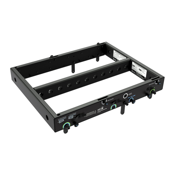
Page 31: Chapter 5: Mg-Mina/Lina/750-Lfc Grid
CHAPTER 5: MG-MINA/LINA/750-LFC GRID The MG-MINA/LINA/750-LFC grid flies LINA arrays of up to 16 cabinets at a 5:1 safety ratio. (Additional load ratings are possible; use MAPP to verify load ratings.) The grid, which can also be used for groundstacking arrays, accommodates a variety of pickup configurations with two front and two rear pickup points and 11 center pickup points. - Page 32 CHAPTER 5: MG-MINA/LINA/750-LFC GRID MG-MINA/LINA/750-LFC Grid Kit Contents Table 3: PN 40.207.101.01 Quantity Part Number Description 45.207.126.01 MG-MINA/LINA/750-LFC grid 134.036 0.25 in x 0.90 in (black button with 6 in lanyard) MG-MINA/LINA/750-LFC Grid Dimensions 2.00 in 51 mm] 24.02 in 20.00 in [610 mm] [508 mm]...
-
Page 33: Mg-Mina/Lina/750-Lfc Grid Load Ratings
MG-MINA/LINA/750-LFC GRID ASSEMBLY GUIDE MG-MINA/LINA/750-LFC GRID LOAD RATINGS The following table lists the maximum suspended weight for the MG-MINA/LINA/750-LFC grid. Table 4: MG-MINA/LINA/750-LFC Load Ratings Orientation Safety Maximum Sus- Maximum Number of Maximum Grid Tilt Factor pended Weight LINA Cabinets Maximum Downtilt 688 lbs (312 kg) ±60°... - Page 34 CHAPTER 5: MG-MINA/LINA/750-LFC GRID...
-
Page 35: Chapter 6: Flying Arrays
CHAPTER 6: FLYING ARRAYS MG-MINA/LINA/750-LFC GRID ORIENTATIONS FOR FLOWN CONFIGURATIONS The orientation of the MG-MINA/LINA/750-LFC grid allows placement of the array’s center of gravity closer to the front or rear of the grid, thereby determining the maximum downtilt or uptilt available for the flown array. Figure 18: LINA Closer to Front of MG-MINA/LINA/750-LFC for Maximum Array Downtilt Figure 19: LINA Closer to Rear of MG-MINA/LINA/750-LFC for Maximum Array Uptilt MG-MINA/LINA/750-LFC Oriented for Maximum Array Downtilt... - Page 36 CHAPTER 6: FLYING ARRAYS 0˚ -5˚ Figure 20: MG-MINA/LINA/750-LFC Grid, Maximum Downtilt Orientation, 0 and –5 Degrees MG-MINA/LINA/750-LFC Oriented for Maximum Array Uptilt When the MG-MINA/LINA/750-LFC grid is oriented so the loudspeaker mounts closer to the rear of the grid, the array’s cen- ter of gravity moves closer to the rear of the grid.
-
Page 37: Mg-Mina/Lina/750-Lfc Pickup Configurations
MG-MINA/LINA/750-LFC GRID ASSEMBLY GUIDE MG-MINA/LINA/750-LFC PICKUP CONFIGURATIONS The MG-MINA/LINA/750-LFC grid accommodates a variety of pickup configurations with its front and rear pickup points (two each) and 11 center pickup points. When possible, use the front and rear pickup points to change the tilt of the grid with the front and rear motors. -
Page 38: Mapp System Design Tool And Rigging Information
MAPP is a powerful, cross-platform application for accurately predicting the coverage pattern, frequency response, impulse response, and maximum SPL output of single or arrayed Meyer Sound loudspeakers. Residing on your local computer, the MAPP client allows configuration of Meyer Sound loudspeaker systems and definition of the environment in which they will operate, including air temperature, pressure, and humidity. - Page 39 MAPP download link. On-screen instructions will provide guidance for the download and installation process. The MAPP client software is regularly upgraded to add support for the latest Meyer Sound loudspeakers and to add feature enhancements. The MAPP database includes nearly all of the current Meyer Sound loudspeakers, subwoofers, and proces- sors.
- Page 40 CHAPTER 6: FLYING ARRAYS 4. If necessary, adjust the MG-MINA/LINA/750-LFC grid height and grid angle to meet the system’s acoustical require- ments. These properties can be adjusted by entering values in the Edit Flown Loudspeaker Properties dialog box (select Edit and scroll down to Edit Flown Loudspeaker Properties to bring up dialog box), or by manually dragging the grid with the Select and Rotate tools in the Sound Field.
- Page 41 MG-MINA/LINA/750-LFC GRID ASSEMBLY GUIDE Figure 25: MAPP Showing Zoomed LINA Array with Center of Gravity See Appendix A, “Assembling Arrays with the Grid,” for array assembly instructions. NOTE:...
- Page 42 CHAPTER 6: FLYING ARRAYS...
-
Page 43: Chapter 7: Mvp Motor Vee Plate
CHAPTER 7: MVP MOTOR VEE PLATE The optional MVP motor Vee plate fine-tunes the horizontal aim of LINA and 750-LFC arrays ±16 degrees. The bottom of the Vee plate attaches to the MG-MINA/LINA/750-LFC grid’s frontmost or rearmost point on the center pickup bar, while the top corners of the Vee plate attach to two motors, which, when adjusted, affect the horizontal rotation of the grid. -
Page 44: Mvp Motor Vee Plate Kit Contents
Use MAPP to determine the weight distribution between the front and rear of the grid. Use the CAUTION: point(s) carrying the lesser weight to attach the MVP motor Vee plate. The MVP motor Vee plate is compatible with any Meyer Sound grid with front and rear center pickup NOTE: points. -
Page 45: Chapter 8: Pbf-Lina Pull-Back Frame
CHAPTER 8: PBF-LINA PULL-BACK FRAME For applications requiring extreme array downtilt that is not possible with adjustments to the motors attached to the grid, the optional PBF-LINA pull-back frame can be attached to the bottom cabinet in LINA and 750-LFC arrays and pulled by a separate motor. -
Page 46: Pbf-Lina Pullback Frame Dimensions
CHAPTER 8: PBF-LINA PULL-BACK FRAME PBF-LINA PULLBACK FRAME DIMENSIONS 5.49 in 139.53 mm 19.59 in 497.68 mm 0.6875 in 17.46 mm 17.18 in 436.43 mm Figure 29: PBF-LINA Pull-Back Frame Dimensions PBF-LINA Pullback Frame Weight: 3.8 lbs (1.7 kg) PBF-LINA PULLBACK FRAME LOAD RATINGS The PBF-LINA pull-back frame has the following maximum load ratings: MINA/LINA: 1,154 lb (524 kg) at a 5:1 safety factor;... - Page 47 MG-MINA/LINA/750-LFC GRID ASSEMBLY GUIDE When configuring arrays with pull-back, when in final position, the pull-back chain should not be CAUTION: more than ±10 degrees from vertical. ≤ 10º Figure 31: Limit on Pull-back Chain Deviation from 0 degrees vertical When flying arrays, the total weight of the array, including any pull-back and pull-up hardware, CAUTION: should be calculated before the array is flown to verify its weight does not exceed the load ratings for the MG-MINA/LINA/750-LFC grid.
-
Page 48: Verifying Pullback Requirements In Mapp
CHAPTER 8: PBF-LINA PULL-BACK FRAME VERIFYING PULLBACK REQUIREMENTS IN MAPP To verify array pull-back requirements in MAPP: 1. Insert the loudspeaker array and configure loudspeaker splay angles: a. Choose Insert > Insert Flown Loudspeaker System. b. In the Flown Loudspeaker System dialog box, at the top of the elements list, set the grid to one of the following options, depending on whether a LINA or 750-LFC is attached to the grid, and whether downtilt or uptilt is required. - Page 49 MG-MINA/LINA/750-LFC GRID ASSEMBLY GUIDE Figure 32: MAPP Display Window Shows Front Rigging Load Weight as a Negative Value—Pull-Back Frame Required Figure 33: MAPP Display Window Shows Addition of Pull-Back Frame Brings Loudspeaker Configuration to Within Safe Limits...
- Page 50 CHAPTER 8: PBF-LINA PULL-BACK FRAME...
-
Page 51: Chapter 9: Groundstacking With The Mg-Mina/Lina/750-Lfc Grid
CHAPTER 9: GROUNDSTACKING WITH THE MG-MINA/LINA/750-LFC GRID The MG-MINA/LINA/750-LFC grid can safely groundstack up to six LINA loudspeakers. The LINA at the bottom of the stack attaches directly to the grid with its GuideALinks and is secured with the quick-release pins (0.25 in x 0.90 in, black button with 6 in lanyard, PN 134.036) included with the grid. -
Page 52: Angles For Groundstacked Linas With The Mg-Mina/Lina/750-Lfc
CHAPTER 9: GROUNDSTACKING WITH THE MG-MINA/LINA/750-LFC GRID ANGLES FOR GROUNDSTACKED LINAS WITH THE MG-MINA/LINA/750-LFC For groundstacked configurations with the MG-MINA/LINA/750-LFC, the angle for the bottom LINA attached to the grid can be from +6 degrees (uptilt) to –5 degrees (downtilt). Table 7 on page 45 lists the available angles and the corresponding label positions for the rear GuideALinks. - Page 53 MG-MINA/LINA/750-LFC GRID ASSEMBLY GUIDE -5° ° -4° -3° -2° -1° 0° 1° 2° 3° 4° 5° 6° Stowed Figure 38: LINA Rear GuideALink Angles for Groundstacked Units Table 7: MG-MINA Groundstack Angles Rear GuideALink Actual Groundstack Label Position Angle –5° –4.5°...
- Page 54 CHAPTER 9: GROUNDSTACKING WITH THE MG-MINA/LINA/750-LFC GRID To groundstack 750-LFCs with the MG-MINA/LINA/750-LFC grid, the 750-LFCs must be equipped with the MRK-750 rig- ging kit. Figure 39: MG-MINA/LINA/750-LFC Grid with Groundstacked 750-LFCs, Exploded View...
-
Page 55: Groundstacking Linas On The 750-Lfc
MG-MINA/LINA/750-LFC GRID ASSEMBLY GUIDE GROUNDSTACKING LINAS ON THE 750-LFC Up to five LINAs can be groundstacked on top of a single 750-LFC (when equipped with the MRK-750 rigging kit). Figure 40: LINAs Groundstacked on 750-LFC, Exploded View To further secure large groundstacks, particularly in outdoor installations with severe wind conditions, CAUTION: attach tie-downs or weights to the grid along with a safety system directly to the groundstack. - Page 56 CHAPTER 9: GROUNDSTACKING WITH THE MG-MINA/LINA/750-LFC GRID...
-
Page 57: Chapter 10: Mya-Mina/Lina Mounting Yoke
CHAPTER 10: MYA-MINA/LINA MOUNTING YOKE The MYA-MINA/LINA mounting yoke flies up to three LINA loudspeakers from a single hanging point, or pole-mounts up to two LINA loudspeakers with a third-party pole-mount adapter. The yoke includes two bracketing options: the MPA-2 bracket for attaching to two cabinets, and the MPA-3 bracket for attaching to one or three cabinets. For larger arrays, the MG-MINA/LINA/750 grid is recommended (see Chapter 5, “MG-MINA/LINA/750-LFC Grid”);... - Page 58 CHAPTER 10: MYA-MINA/LINA MOUNTING YOKE MYA-MINA/LINA Kit Contents Table 8: MYA-MINA/LINA (PN 40.207.104.01) Part Number Quantity Description 45.207.135.01 MYA-MINA/LINA yoke assembly 64.207.155.01 MPA-3 Bracket (right) for one or three cabinets 64.207.156.01 MPA-3 Bracket (left) for one or three cabinets 64.207.157.01 MPA-2 Bracket for two cabinets 124.115 Knobs, M6 x 1 x 20 mm...
- Page 59 MG-MINA/LINA/750-LFC GRID ASSEMBLY GUIDE MYA-MINA/LINA Dimensions 6.25 in [159 mm] (x6) Ø0.28 in [Ø7 mm] Ø0.56 in 2.00 in [Ø14 mm] [51 mm] 4.00 in 22.53 in [102 mm] [572 mm] 17.49 in [444 mm] Ø0.28 in [Ø7 mm] 20.03 in [509 mm] Figure 43: MYA-MINA/LINA Dimensions MYA-MINA/LINA Weight: 12.9 lbs (5.85 kg)
-
Page 60: Mya-Mina/Lina Load Ratings
CHAPTER 10: MYA-MINA/LINA MOUNTING YOKE MYA-MINA/LINA LOAD RATINGS An array of up to three LINA loudspeakers can be flown with the MYA-MINA mounting yoke at a 5:1 safety factor. When fly- ing any number of LINAs with the yoke, the yoke must be secured to the mounting surface with the 1/2-inch center hole. Table 9: MYA-MINA/LINA Load Ratings Mounting Point Safety... -
Page 61: Mya-Mina/Lina Bracket Options
MG-MINA/LINA/750-LFC GRID ASSEMBLY GUIDE MYA-MINA/LINA BRACKET OPTIONS The MYA-MINA mounting yoke includes two side bracketing options: the MPA-2 for attaching to two cabinets, and the MPA-3 for attaching to one or three cabinets. The bracket options allow the yoke to attach near the center of gravity for the loudspeakers. -
Page 62: Mya-Mina/Lina Flown Configurations
CHAPTER 10: MYA-MINA/LINA MOUNTING YOKE MYA-MINA/LINA FLOWN CONFIGURATIONS The MYA-MINA mounting yoke flies up to three LINA loudspeakers from a single hanging point. The yoke attaches to the side brackets (which attach directly to the LINA end frames) and is secured with the included M6 screws in the center pivot holes, and the M6 knobs in one of three pinning holes. - Page 63 MG-MINA/LINA/750-LFC GRID ASSEMBLY GUIDE The M6 screws can be used in the pinning holes for fixed installations that will not require tilt adjustments TIP: for the loudspeakers. For installations that will require tilt adjustments, use the M6 knobs in the pinning holes, as they are more easily loosened and tightened.
-
Page 64: Mya-Mina/Lina Pole-Mount Configurations
CHAPTER 10: MYA-MINA/LINA MOUNTING YOKE MYA-MINA/LINA POLE-MOUNT CONFIGURATIONS Up to two LINA loudspeakers can be pole-mounted with the MYA-MINA/LINA mounting yoke. The yoke attaches to the side brackets (which attach directly to the LINA end frames) and is secured with the included M6 screws in the center, pivot holes, and the M6 knobs in one of three pinning holes. -
Page 65: Chapter 11: Mub-Mina/Lina U-Bracket
CHAPTER 11: MUB-MINA/LINA U-BRACKET The MUB-MINA/LINA U-bracket (Figure 51) was primarily designed for aiming a single LINA loudspeaker in floor- and ceil- ing-mount configurations (Figure 52). However, the U-bracket is strong enough to support arrays of up to five cabinets, or to stack up to two cabinets in floor- and pole-mount configurations. - Page 66 CHAPTER 11: MUB-MINA/LINA U-BRACKET MUB-MINA/LINA Kit Contents Table 10: MUB-MINA/LINA Kit Contents (PN 40.207.030.01) Part Number Quantity Description 45.207.030.01 MUB-MINA/LINA U-bracket 101.840 Screws, M6 x 1 x 22 mm 113.521 Flat washers, M6 115.531 Lock washers, M6 MUB-MINA/LINA Dimensions 16.00 in [406 mm] 5.00 in [127 mm]...
-
Page 67: Mub-Mina/Lina Load Ratings
MG-MINA/LINA/750-LFC GRID ASSEMBLY GUIDE MUB-MINA/LINA LOAD RATINGS An array of up to five LINA loudspeakers can be flown with the MUB-MINA/LINA U-bracket at a 5:1 safety factor. When fly- ing any number of LINAs with the U-bracket, the U-bracket must be secured to the mounting surface with either the two 1/2-inch center holes or the four 1/4-inch corner holes. - Page 68 CHAPTER 11: MUB-MINA/LINA U-BRACKET Table 12: MUB-MINA/LINA Flown, Fixed Angles Flown, Maximum Downtilt Flown, Maximum Uptilt Fixed (0°, –5°) Fixed (–5°, –10°) -5° 0° -5° -10° Table 13: MUB-MINA/LINA Flown, Adjustable Angles Flown, Maximum Downtilt Flown, Maximum Uptilt Adjustable (0° to 20°) Adjustable (–10°...
-
Page 69: Mub-Mina/Lina Floor-Mount Configurations
MG-MINA/LINA/750-LFC GRID ASSEMBLY GUIDE MUB-MINA/LINA FLOOR-MOUNT CONFIGURATIONS The MUB-MINA/LINA U-bracket can be mounted to a floor to aim a single LINA loudspeaker, or it can be used for stacking up to two LINA loudspeakers. The MUB-MINA/LINA U-bracket should be secured to the floor with fasteners placed in its four corner holes. - Page 70 CHAPTER 11: MUB-MINA/LINA U-BRACKET Table 14: MUB-MINA/LINA Floor/Pole-Mount, Fixed Angles Flown/Pole-Mount, Maximum Downtilt Floor/Pole-Mount, Maximum Uptilt Fixed (+5°, +10°) Fixed (0°, +5°) 0° +5° +10° +5° Table 15: MUB-MINA/LINA Floor/Pole-Mount, Adjustable Angles Floor/Pole-Mount, Maximum Downtilt Floor/Pole-Mount, Maximum Uptilt Adjustable (+10° to –10°) Adjustable (0°...
-
Page 71: Mub-Mina/Lina Pole-Mount Configurations
MG-MINA/LINA/750-LFC GRID ASSEMBLY GUIDE MUB-MINA/LINA POLE-MOUNT CONFIGURATIONS Up to two LINA loudspeakers can be pole-mounted with the MUB-MINA/LINA U-bracket. The MUB-MINA/LINA U-bracket should be secured to the pole-mount adapter with fasteners placed in the U-bracket’s two 1/4-inch, non-threaded, center holes. The LINA cabinet is secured to the U-bracket with the screws and washers included with the MUB-MINA/LINA kit. A second LINA cabinet can be stacked on top of the first cabinet and secured with the top unit’s GuideALinks. -
Page 72: Mub-Mina/Lina Ceiling-Mount Configurations
CHAPTER 11: MUB-MINA/LINA U-BRACKET MUB-MINA/LINA CEILING-MOUNT CONFIGURATIONS The MUB-MINA/LINA U-bracket can be mounted to a ceiling to aim a single LINA loudspeaker, or it can be used for arrays of up to five LINA loudspeakers when using the four 1/4-inch corner holes (see Table 11). The MUB-MINA/LINA U-bracket should be secured to the ceiling with fasteners placed in its four 1/4-inch, corner holes. -
Page 73: Mub-Mina/Lina Flown Configurations
MG-MINA/LINA/750-LFC GRID ASSEMBLY GUIDE MUB-MINA/LINA FLOWN CONFIGURATIONS The MUB-MINA/LINA U-bracket with up to two LINA can be flown from a truss with two C-clamps attached to the bracket’s two 1/2-inch center holes (see Table 11). Make sure to use rigging hardware rated to meet or exceed the weight of the U- bracket and suspended loudspeakers. - Page 74 CHAPTER 11: MUB-MINA/LINA U-BRACKET...
-
Page 75: Chapter 12: Mpk Pole And Pole-Mount Receptacle
POLE-MOUNT RECEPTACLE All 750-LFCs come standard with an integral pole-mount receptacle that allows the subwoofer to be easily paired with ULTRA series loudspeakers. You can mount Meyer Sound loudspeakers on top of the 750-LFC with a heavy-duty pole and pole-stand adapter. - Page 76 CHAPTER 12: MPK POLE AND POLE-MOUNT RECEPTACLE The following Meyer Sound loudspeakers can be mounted on top of the 750-LFC. Make sure that the pole and pole-mount adapter can support the weight of the mounted loudspeakers and that they are installed according to the manufacturer’s instructions.
-
Page 77: Chapter 13: The Mcf-Mina/Lina Caster Frame
CHAPTER 13: THE MCF-MINA/LINA CASTER FRAME The MCF-MINA/LINA caster frame safely supports up to five LINAs for transport and groundstacking, making it easy to assemble or disassemble arrays. The caster frame’s sturdy construction allows it be conveniently moved with forklifts. Figure 59: MCF-MINA/LINA Caster Frame The LINA at the bottom of the stack attaches securely to the caster frame with its GuideALinks and is secured with the four quick-release pins (0.25 in x 0.90 in, black button with 6-inch lanyard, PN 134.036) included with the caster frame. - Page 78 CHAPTER 13: THE MCF-MINA/LINA CASTER FRAME MCF-MINA/LINA Dimensions 23.96 in [609 mm] 14.50 in [368 mm] 18.46 in [469 mm] 20.40 in [518 mm] 18.67 in [474 mm] 7.25 in [184 mm] 17.00 in [432 mm] Figure 60: MCF-MINA/LINA Caster Frame Dimensions MCF-MINA/LINA Weight: 28.0 lbs (12.7 kg) Table 17: Loudspeaker to MCF-MINA/LINA Angles Rear GuideALink...
- Page 79 MG-MINA/LINA/750-LFC GRID ASSEMBLY GUIDE Figure 62: MCF-MINA/LINA Caster Frame with LINA Stack The MG-MINA/LINA grid can travel installed on top of LINA stacks. TIP: Durable nylon covers, sized for stacks of 3, 4, and 5 units, are available to ensure the LINA is completely TIP: road ready.
-
Page 80: Safety Guidelines For The Mcf-Mina/Lina Caster Frame
CHAPTER 13: THE MCF-MINA/LINA CASTER FRAME SAFETY GUIDELINES FOR THE MCF-MINA/LINA CASTER FRAME Do not stack more than five LINAs. • Avoid moving stacks in the front-to-back direction of the LINAs (the long side); always move stacks sideways to avoid •... -
Page 81: Chapter 14: Mcf-750 Caster Frame
CHAPTER 14: MCF-750 CASTER FRAME The MCF-750 caster frame safely transports up to three 750-LFCs, making it easy to assemble and disassemble arrays in blocks of three cabinets. There are two versions available, one for MRK-750-equipped cabinets (PN 40.271.070.02), the other for cabinets without rigging (PN 40.271.070.03). - Page 82 CHAPTER 14: MCF-750 CASTER FRAME Two versions of the MCF-750 caster frame are available from the factory—configured for cabinets with NOTE: the MRK-750 rigging kit (PN: 40.271.070.02) or without (PN: 40.271.070.03). 750-LFC cabinets need not be equipped with the MRK-750 rigging kit for transport with the caster frame. The loudspeaker skids ensure that cabinets stack cleanly on the caster frame.
- Page 83 MG-MINA/LINA/750-LFC GRID ASSEMBLY GUIDE 750-LFC cabinets equipped with the MRK-750 rigging kit provide for more secure transport as the bottom cabinet can be linked and pinned to the caster frame. The three cabinets can be linked and pinned together as well. Figure 67: MCF-750 Caster Frame, (3) 750-LFCs (with Rigging) Durable nylon pullover covers, sized for stacks of 2 units or 3 units, are available to protect 750-LFC cabi- TIP:...
-
Page 84: Dimensions: Mcf-750 Caster Frame With Rigging
CHAPTER 14: MCF-750 CASTER FRAME DIMENSIONS: MCF-750 CASTER FRAME WITH RIGGING 24.91 in [633 mm] 24.16 in 24.16 in [614 mm] [614 mm] 7.50 in 5.85 in [190.5 mm] [149 mm] 17.70 in 17.14 in [450 mm] [435 mm] Figure 68: MCF-750 Caster Frame (for cabinets with rigging) Dimensions MCF-750 Caster Frame with Rigging Weight: 34 lbs (15.4 kg) -
Page 85: Dimensions: Mcf-750 Caster Frame Without Rigging
MG-MINA/LINA/750-LFC GRID ASSEMBLY GUIDE DIMENSIONS: MCF-750 CASTER FRAME WITHOUT RIGGING 24.16 in [614 mm] 24.91 in [633 mm] 7.50 in 5.85 in [190 mm] [149 mm] 17.14 in 17.70 in [435 mm] [450 mm] Figure 69: MCF-750 Caster Frame (for cabinets without rigging) Dimensions MCF-750 Caster Frame without Rigging Weight: 28.7 lbs (13.0 kg) SAFETY GUIDELINES FOR THE MCF-750 CASTER FRAME Do not stack more than three cabinets on the MCF-750 caster frame. - Page 86 CHAPTER 14: MCF-750 CASTER FRAME...
-
Page 87: Appendix A: Assembling Arrays With The Grid
APPENDIX A: ASSEMBLING ARRAYS WITH THE GRID The quick-release pins (0.25 in x 0.53 in, black button, PN 134.039 that are included with each LINA NOTE: are referred to as loudspeaker pins below. The quick-release pins (0.25 in x 0.90 in, black button with 6 in lan- yard, PN 134.036) that come with the grid are referred to as grid pins. - Page 88 APPENDIX A: ASSEMBLING ARRAYS WITH THE GRID 9. Raise the grid so the suspended loudspeakers are slightly off the floor and remove the two rear quick-release pins secur- ing the bottom cabinet’s GuideALinks to the caster frame. Rest the rear wheels of the caster frame on the floor and remove the two front quick-release pins to detach the caster frame from the bottom cabinet.
- Page 89 MG-MINA GRID ASSEMBLY GUIDE As the flown array is assembled and raised, LINA’s front GuideALinks can rotate over 30 degrees forward TIP: while pinned, facilitating the connection of the flown, angled array to the loudspeakers on the caster frame. Roll the stack into position so the front GuideALinks align.
- Page 90 APPENDIX A: ASSEMBLING ARRAYS WITH THE GRID...
-
Page 91: Appendix B: Ultra Weather Protection Version
For installations in extremely harsh environments, Meyer Sound offers an Ultra Weather Protection option for the LINA loudspeaker, which includes all of the components of standard Weather Protection, plus the following: Extended cabinet finishing with extra thick proprietary coatings •... - Page 92 APPENDIX B: ULTRA WEATHER PROTECTION VERSION...
- Page 96 Meyer Sound Laboratories Inc. © 2019 2832 San Pablo Avenue Meyer Sound. All rights reserved. Berkeley, CA 94702 +1 510 486.1166 MG-MINA/LINA/750-LFC Assembly Guide PN 05.207.101.02 www.meyersound.com...
Need help?
Do you have a question about the LEO Series and is the answer not in the manual?
Questions and answers