Sign In
Upload
Manuals
Brands
Advantech Manuals
Controller
PCI-1242
Advantech PCI-1242 Manuals
Manuals and User Guides for Advantech PCI-1242. We have
1
Advantech PCI-1242 manual available for free PDF download: User Manual
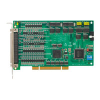
Advantech PCI-1242 User Manual (104 pages)
4-Axis Voltage/Pulse-type Servo Motor Control Card
Brand:
Advantech
| Category:
Controller
| Size: 1.52 MB
Table of Contents
Packing List
5
Table of Contents
7
General Information
11
Chapter 1 Introduction
12
Introduction
12
Features
13
Applications
14
How to Get Started
14
Figure 1.1:Installation Flow Chart
15
Software Programming Choices
16
Accessories
16
Wiring Cables
16
Wiring Board
16
Chapter 2 Installation
18
Software Installation
18
Figure 2.1:The Setup Screen of Advantech Automation Software
18
Hardware Installation
19
Board Layout and Jumper/Switch Settings
20
Chapter 3 Signal Connections
24
I/O Connector Pin Assignments
24
Figure 3.1:J1 Remote I/O Connector Pin Assignments
24
Figure 3.2:J2 Remote I/O Connector Pin Assignments
25
Table 3.1:PCI-1241/1242 I/O J1 Conn. Signal Descrip Tion – Remote I/O
25
Figure 3.3:J3 MPG Connector Pin Assignments
26
Table 3.2:PCI-1241/1242 I/O J2 Conn. Signal Descrip Tion – Remote I/O
26
Table 3.3:PCI-1241/1242 I/O J3 Conn. Signal Descrip Tion – MPG Input
27
Table 3.4:PCI-1241/1242 I/O Conn. Signal Desc. – DDA Pulse Output
29
Table 3.5:PCI-1241/1242 I/O Conn. Signal Desc. – en Coder Input
30
Table 3.6:PCI-1241/1242 I/O Connector Signal Descrip Tion – Local I/O
31
Table 3.7:PCI-1241 I/O Conn. Signal Desc. – Voltage Output & Others
32
Voltage Output Connection (PCI-1241 Only)
33
Voltage Output Specifications
33
Wiring Consideration
33
Motor Driver
34
Pulse Output Connection
35
Figure 3.6:Differential Signal Transmission Method
35
Figure 3.7:Pulse Output Format
36
Figure 3.8:Wiring Diagram between PCI-1241/42 and Pulse-Type Driver
37
Local Input Connection
37
Figure 3.9:Local Input Wiring Diagram
39
Local Output Connection
39
Figure 3.10:Local Output Wiring Diagram
40
Local I/O Wiring Example
41
MPG Encoder Input Connection
44
Figure 3.13:MPG Encoder Input DB-9 Connector Pin as Signment
45
Figure 3.14:MPG Encoder Input Wiring Diagram
45
Remote I/O Connection
46
Figure 3.16:Remote I/O Wiring Diagram in PCI-1241
46
Figure 3.17:Remote I/O Wiring Diagram in PCI-1242
47
Field Wiring Considerations
48
Chapter 4 Configuration Utility
50
Figure 4.1:Configuration Utility Main
50
Utility Main Page
50
Figure 4.2:Utility Operation Flow Chart
51
Select Device
51
Figure 4.3:Select Device Dialog Window
51
Set Parameters
52
Mechanism Configuration
52
Figure 4.4:Mechanism Configuration
52
Figure 4.5:Mechanical Parameter Definition
53
General/Ptp Motion Configuration
55
Figure 4.6:General/Ptp Configuration
56
System Configuration
56
Figure 4.7:System Configuration
57
Home Configuration
57
Figure 4.8:Home Configuration
58
Initializing the Card
59
Figure 4.9:The Card Is Now Active
59
Servo on
59
Operate Motor
60
PCI-1241/1242 User Manual
60
Figure 4.10:Operation Main Page of Test Utility
60
Figure 4.11:Point-To-Point Motion Configuration Win Dow
61
Figure 4.12:Line Command Configuration Window
61
Motion Command
61
Figure 4.13:2D Circle Motion Configuration Window
62
Figure 4.14:2D Circle with Line Motion Configuration Window
62
Figure 4.15:3D Arc Motion Configuration Window
62
Dow
63
Figure 4.16:2D Arc Motion Configuration Window
63
Figure 4.17:3D Arc with Line Motion Configuration Win Dow
63
Figure 4.18:Jog Configuration Dialog Box
63
Jog
63
Figure 4.19:Home Motion Configuration Window
64
Figure 4.20:Remote I/O Status Window
64
Home
64
Remote IO Page
64
Figure 4.21:Motion Profile Display Window
65
Motion Profile
65
Chapter 5 Software Startup Guide
68
Card Index Manager
68
Figure 5.1:Card Index Manager
68
Sample Program Usage
69
Table 5.1:Sample Program Usage
69
Appendix A Specifications
74
Axis
74
A.1 Axis
74
Voltage Output: (PCI-1241 Only)
75
Pulse Output
76
A.3 Pulse Output
76
Encoder Input
77
A.4 Encoder Input
77
Local Input/Output
78
Other Motion Functions
79
General
79
A.7 General
79
Block Diagram
81
Appendix B Block Diagram
82
Figure B.1:PCI-1241/1242 System Block Diagram
82
Open Loop Motion Control (Pulse Command)
83
Digital Differential Analyzer (DDA)
83
Figure B.2:DDA Example
83
Close Loop Motion Control (Velocity Command)
84
Local Input / Output
85
Remote Input / Output
85
Appendix C Home Function
88
How to Read the Home Velocity Profile
88
Home Mode0
89
C.2 Home Mode0
89
Figure C.1:Velocity Profile of Home Mode0
89
Home Mode1
90
C.3 Home Mode1
90
Figure C.2:Velocity Profile of Home Mode1
90
Home Mode2
91
C.4 Home Mode2
91
Figure C.3:Velocity Profile of Home Mode2
91
Home Mode3
92
C.5 Home Mode3
92
Figure C.4:Velocity Profile of Home Mode3
92
Home Mode4
93
C.6 Home Mode4
93
Figure C.5:Velocity Profile of Home Mode4
93
Home Mode5
94
C.7 Home Mode5
94
Figure C.6:Velocity Profile of Home Mode5
94
Home Mode6
95
Home Mode7
95
C.8 Home Mode6
95
Figure C.7:Velocity Profile of Home Mode6
95
C.9 Home Mode7
95
Figure C.8:Velocity Profile of Home Mode7
95
C.10 Home Mode8
96
Figure C.9:Velocity Profile of Home Mode8
96
Home Mode8
96
C.11 Home Mode9
97
Figure C.10:Velocity Profile of Home Mode9
97
Home Mode9
97
C.12 Home Mode10
98
Figure C.11:Velocity Profile of Home Mode10
98
Home Mode10
98
C.13 Home Mode11
99
Figure C.12:Velocity Profile of Home Mode11
99
Home Mode11
99
C.14 Home Mode12
100
C.15 Home Mode13
100
Figure C.13:Velocity Profile of Home Mode12
100
Figure C.14:Velocity Profile of Home Mode13
100
Home Mode12
100
Home Mode13
100
Appendix D Remote I/O
102
Features
102
D.1 Features
102
Specifications
103
D.2 Specifications
103
Figure D.1
103
Figure D.2
103
Advertisement
Advertisement
Related Products
Advantech PCI-1241
Advantech PCL-839+
Advantech PCI-1240
Advantech PCI-1240U
Advantech PCI-1220U
Advantech PCI-1202
Advantech PCI-1243U
Advantech PCI-1710U
Advantech PCI-1682U
Advantech PCI-1716L
Advantech Categories
Motherboard
Computer Hardware
Desktop
Network Router
Touch Panel
More Advantech Manuals
Login
Sign In
OR
Sign in with Facebook
Sign in with Google
Upload manual
Upload from disk
Upload from URL