Danfoss ECL Comfort 100M User's Manual And Installation Instructions
Danfoss ecl comfort controller - user's guide and installation instructions
Hide thumbs
Also See for ECL Comfort 100M:
- User manual (89 pages) ,
- User manual (47 pages) ,
- User manual (82 pages)

Related Manuals for Danfoss ECL Comfort 100M


Summary of Contents for Danfoss ECL Comfort 100M
- Page 1 ECL Comfort 100M User’s Guide and Installation 2004.05 *087R9728* *vi7ab402* ECL Comfort 100M User’s Guide and Installation 2004.05 *087R9728* *vi7ab402*...
-
Page 2: Table Of Contents
Table of contents Page No. User’s Guide Before you start Operating the controller Setting the clock Individual comfort and reduced comfort periods Controller mode Temperature setting Temperature reduction Setting the heat curve Controller settings on the rear side Installation and maintenance Before you start Identifying the system type Mounting the controller... -
Page 3: User's Guide Before You Start
Before you start Save energy - save money - improve your comfort temperature The ECL Comfort controller is designed by Danfoss for the automatic temperature control of heating sys tems. The advantages of the ECL Comfort controller system are the security of your heating control and the op ti mum use of energy resources. -
Page 4: Operating The Controller
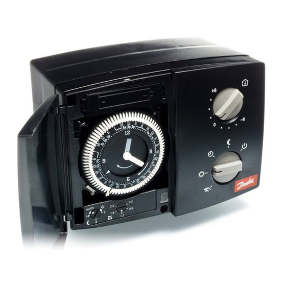
Operating the controller Setting the clock Clock (optional) A clock can be mounted when an automatic change between comfort temperature and reduced temperature is desired. Setting the clock Turn the minute hand to set the actual week day (7-day clock) and time. -
Page 5: Controller Mode
Controller mode What do the symbols mean? Manual operation. Used only at maintenance and service. Note! The system protection against frost is switched off when this mode is selected. Constant comfort temperature. The day plan is not in operation. Used when ex tend ed pe ri ods of comfort temperature are desired, i.e. -
Page 6: Temperature Setting
Temperature setting Temperature setting without room sensor (parallel displacement of the heat curve) If you have no room sensor installed, your system will not know the exact room temperature. Therefore you can only use the temperature setting button to change the fl ow temperature. -
Page 7: Temperature Reduction
Temperature reduction The knob (potentiometer) for the temperature reduction can be set in the positions of (standby), 1 - 14 or AUTO: Heating system on standby The heating system is stopped, but still protected against frost. 1 - 14 Fixed temperature reduction Without room sensor: The fl... -
Page 8: Setting The Heat Curve
Setting the heat curve ˚C The heat curve shows the relation between the outdoor ˚C tem per a ture and the fl ow temperature of the heating circuit. You can set the heating curve slope in the range from 0.2 to 2.2. The slope is factory set to 1.2. -
Page 9: Controller Settings On The Rear Side
Controller settings on the rear side To make the controller ready for operation, you must Switch 1: Heating cut-out adjust the controller settings on the rear side. Switch 1 Cut-out temperature Your setting Mini switches 1 to 8: No cut-out 18 ºC The heating cut-out function helps you save energy. - Page 10 Switch 3: Maximum fl ow temperature limit Switch 5: Gear motor/thermo actuator Switch 3 Max. fl ow temperature Your setting Switch 5 Actuator type Your setting 45 ºC Thermo actuator 90 ºC Gear motor Set a maximum fl ow temperature to protect your heating Select the gear motor or thermo actuator, depending on what sys tem from getting overheated.
-
Page 11: Installation And Maintenance Before You Start
Before you start Save energy - save money - improve your comfort temperature The ECL Comfort controller is designed by Danfoss for tem per a ture con trol of heating systems. The ECL Comfort ensures you of the following; •... -
Page 12: Identifying The System Type
Identifying the system type The ECL Comfort controller is capable of controlling diff erent Heating system type 1: Direct district heating heating systems. These standard system types cov er a variety of system compositions. If your system is not quite as the diagrams of the most frequently used systems, fi... -
Page 13: Mounting The Controller
Mounting the controller Mounting on a wall You should mount the ECL Comfort controller for easy access near the heating unit. You can choose between three Order mounting kit No. 087B1154. methods: Mount the terminal box on a wall with a smooth surface. •... -
Page 14: Placing The Temperature Sensor Types
(ESMU, ESM-11 or ESMC types) Place the sensor max. 15 cm from the mixing point. In systems with heat exchanger, Danfoss recommends the ESMU-type to be inserted into the exchanger fl ow outlet. Make sure that the surface of the pipe is clean where the sen sor is to be mounted. -
Page 15: Electrical Connections
Electrical connections 230 V a.c. Electrical connections 24 V a.c. Terminal Description Max. load Terminal Description Max. load Voltage supply 230 V a.c. Voltage supply 24 V a.c. Voltage supply 230 V a.c. Voltage supply 24 V a.c. Gear motor - open 0.2 VA 230 V a.c. -
Page 16: Electrical Connections
Electrical connections - sensors LED indication Function test The LED indicator shows wheth er the 100M is in op er a tion or not. When testing sensors and controller, the con trol status and faults are shown. Control status At normal operation with the function switch in the positions the indicator lights. -
Page 17: Check List
✐ Check list Is the ECL Comfort controller ready for use? Check that all sensors are connected to the correct ter mi nals. See page 28: Electrical connections - sensor Make sure that the power supply is wired correctly to the terminals 1 (Live) and 2 (Neutral). Mount the controller, switch on the power. -
Page 18: Communication
Communication The ECL Comfort controller can be connected to external units via the ECL Comfort BUS. Master / slave systems If the controller is part of a larger system with several controllers, you can connect the controllers with each other and send information to them using the same outdoor sensor. -
Page 19: Power Back-Up
To ensure power back-up there is a battery placed above the clock. Normally this battery is not in operation. However Danfoss recommends to replace it every 2 years. Use an Alcaline AAA 1.5 V type. Remove the battery holder and replace the battery. -
Page 20: Defi Nitions
Defi nitions Actual flow temperature Heating circuit The temperature that is measured in the fl ow at any The circuit for heating the room/building. time. Pt 1000 ohm sensor Comfort period All sensors used with the ECL Comfort controller is based on A period of the day where comfort temperature is the Pt 1000 ohm type.
Need help?
Do you have a question about the ECL Comfort 100M and is the answer not in the manual?
Questions and answers