Table of Contents
Advertisement
Model 591XV
Installation Guide
NOTE:
This product is intended for installation by a professional installer only!
Any attempt to install this product by any person other than a trained professional
may result in severe damage to a vehicle's electrical system and components.
© 2003 Directed Electronics, Inc. Vista, CA
N542V 6-03
Advertisement
Table of Contents

Related Manuals for Directed Electronics 591XV


Summary of Contents for Directed Electronics 591XV
- Page 1 This product is intended for installation by a professional installer only! Any attempt to install this product by any person other than a trained professional may result in severe damage to a vehicle’s electrical system and components. © 2003 Directed Electronics, Inc. Vista, CA N542V 6-03...
-
Page 2: Table Of Contents
(p/n 998T) Soft Chirp®, Stinger®, Valet®, Vehicle Recovery System®, VRS®, and Warn Away® are all requires chip version 1.5 or Trademarks or Registered Trademarks of Directed Electronics, Inc. newer to program this unit. © 2003 Directed Electronics, Inc. Vista, CA... -
Page 3: Warning! Safety First
This testing should be performed by an authorized Directed Electronics dealer in accordance with the Safety Check outlined in this product installation guide. If the vehicle starts in gear, cease remote start operation immediately and consult with the user to fix the problem immediately. -
Page 4: Installation Points To Remember
When locating the control module, try to find a secure location that will not require you to extend the harness wires (they are 1.5 meters long). © 2003 Directed Electronics, Inc. Vista, CA... -
Page 5: Valet/Program Switch
It is easiest to use a small removable panel, such as a switch blank or a dash bezel. Remove it before drilling your -inch hole. Use quick-disconnects near the LED wires if the panel is removable. This lets mechanics or other installers remove the panel without having to cut the wires. © 2003 Directed Electronics, Inc. Vista, CA... -
Page 6: Optional Starter Kill Relay
IMPORTANT! Do not remove the fuse holder on the red wire. It ensures that the control module has its own fuse, of the proper value, regardless of how many accessories are added to the main power feed. © 2003 Directed Electronics, Inc. Vista, CA... -
Page 7: Finding The 12V Switched Ignition Wire
A cold start circuit will test exactly like a starter circuit, but it does not control the starter. Instead, the cold start circuit is used to prime the fuel injection system for starting when the vehicle is cold. © 2003 Directed Electronics, Inc. Vista, CA... -
Page 8: Finding A (+) Brake Light Wire
Some vehicles may have separate wires for the blower motor and the air conditioning compressor. In such cases, it will be necessary to add a relay to power the second accessory wire. © 2003 Directed Electronics, Inc. Vista, CA... -
Page 9: Finding The Rpm Input Wire
(ground while the bulb is on). 6. If the meter reads zero volts until the light goes out and then reads 12 volts, you have isolated the correct wire and the wire's polarity is positive. © 2003 Directed Electronics, Inc. Vista, CA... -
Page 10: Wiring Diagrams
(H1) wiring diagram The primary harness supplied with this unit is the standard 12-pin harness used by Directed Electronics, Inc. security systems. Three wires in the plug are not used. The upgrade from this unit to a security system would simply require unplugging and exchanging control units and connecting the necessary wires to the vehicle. -
Page 11: Remote Start Ribbon Harness Wiring Diagram
(+) OUTPUT TO ACCESSORY CIRCUIT ______ (+) (30A) HIGH CURRENT 12V INPUT ______ PINK (+) OUTPUT TO IGNITION CIRCUIT ______ RED/WHITE HIGH CURRENT 12V INPUT ______ PINK/WHITE (+) OUTPUT TO SECOND IGNITION/ACCESSORY CIRCUIT © 2003 Directed Electronics, Inc. Vista, CA... -
Page 12: Auxiliary Harness (H2) Wiring Diagram
______ BLUE (-) 200 mA STATUS OUTPUT ______ ORANGE (-) 200 mA ACCESSORY RELAY TRIGGER ______ PINK (-) 200 mA IGNITION RELAY TRIGGER ______ PURPLE (-) 200 mA STARTER RELAY TRIGGER © 2003 Directed Electronics, Inc. Vista, CA... -
Page 13: Primary Harness (H1) Wire Connection Guide
This wire supplies a (-)500 mA ground as long as the system is armed. This output ceases as soon as the system is disarmed. The orange wire may be wired to an optional Directed Electronics, Inc. 8618 starter kill relay. - Page 14 This output is used for progressive door unlock. A progressive unlock system unlocks the driver's door when the- unlock (disarm) button is pressed and unlocks the passenger doors if the unlock (disarm) button is pressed again © 2003 Directed Electronics, Inc. Vista, CA...
- Page 15 This wire will also output pulses for 30 seconds when the Panic Mode is activated. If the vehicle has a (+) horn circuit, an optional relay can be used to interface with the system, as shown below. © 2003 Directed Electronics, Inc. Vista, CA...
- Page 16 IMPORTANT! Never use this wire to drive anything except a relay or low-current input! The transistorized output can only supply 200 mA of current. Connecting directly to a solenoid, motor, or other high-current device will cause it to fail. © 2003 Directed Electronics, Inc. Vista, CA...
-
Page 17: Relay Key Switch Interface Wire Connection Guide
Connect this wire to the second ignition or accessory wire in the vehicle (selectable menu feature 2-9). RED/WHITE 12 V input If additional current capacity is needed cut this wire, add a fuse adaquate for the circuit to be supplied, and connect to an additional 12V source. © 2003 Directed Electronics, Inc. Vista, CA... -
Page 18: Auxiliary Harness (H2) Wire Connection Guide
Dodge Ram Trucks: Orange/Black or Black/Orange NOTE! A 1-amp diode must be installed in line on the factory wire between the wait-to-start indi- cator and the ECM. (See the following diagram for details.) © 2003 Directed Electronics, Inc. Vista, CA... - Page 19 Use a relay to send a (-) or (+) pulse to the disarm wire as shown in the following diagrams. Relay for Negative (-) Disarm Wire Relay for Positive (+) Disarm Wire © 2003 Directed Electronics, Inc. Vista, CA...
-
Page 20: Remote Start Harness (H3) Wire Connection Guide
In these vehicles, connect this wire to the toggle switch as shown in Figure B. Connect the other wire from the toggle switch to chassis ground. © 2003 Directed Electronics, Inc. Vista, CA... -
Page 21: Neutral Safety Switch Interface
We suggest the following procedure to test for vehicles manufactured in this way. NOTE: You must complete the remote start system installation before doing the following test. Ensure that the remote start system is functioning normally. This includes connecting to the brake as a shut-down. © 2003 Directed Electronics, Inc. Vista, CA... -
Page 22: Testing The Neutral Safety Switch
If the vehicle is not a General Motors product or a Dodge Dakota pickup, please call Directed Electronics, Inc. Technical Support for an alternative shut-down method. Do not return the vehicle to the customer until this feature is prop- erly installed! Every vehicle built this way requires that the shifter be placed in park to remove the keys from the ignition. - Page 23 Diagram A - General Motors trucks, sport utility vehicles and column shifting passenger vehicles: Diagram B - Pre-1996 Dodge Dakota pickups with 2.5 liter motors: © 2003 Directed Electronics, Inc. Vista, CA...
-
Page 24: 1995 And Newer Vehicle Anti-Theft Systems
Upon activation, the transceiver will excite the transponder, which is located (but not visible) in the head of the ignition key. The key © 2003 Directed Electronics, Inc. Vista, CA... -
Page 25: Bypassing Gm Vehicle Anti-Theft Systems (Vats)
NOTE: When connecting to the VATS wires, it is not important which wire is cut. TO IGNITION KEY SWITCH PROPER RESISTOR VALUE H3/1 BLUE OR H3/2 BLUE/BLACK 87 87A (+) 12V CONSTANT FUSED TO VATS DECODER MODULE DIA-621 © 2003 Directed Electronics, Inc. Vista, CA... -
Page 26: Plug-In Led And Valet/Program Switch
When the learn routines have previously been programmed using the Bitwriter, they may have been locked. Before proceeding with reprogramming the learn routines, they must be unlocked with the Bitwriter - this cannot be done manually with the Valet switch. © 2003 Directed Electronics, Inc. Vista, CA... -
Page 27: Programming Jumpers
ON setting changes the trigger threshold of the digital tach circuit so it will work properly with these vehi- cles. The vehicles affected include many newer Dodge/Chrysler/Plymouth vehicles, such as the Neon, Cirrus, Stratus, Breeze and LH-based vehicles. © 2003 Directed Electronics, Inc. Vista, CA... -
Page 28: Transmitter/Receiver Learn Routine
**NOTE: If any button from a known transmitter is programmed to Channel 11, all transmit- ters will be erased from memory and will revert to the default feature settings. This is useful in cases where the customer's transmitters are lost or stolen. © 2003 Directed Electronics, Inc. Vista, CA... - Page 29 Learn Routine will be exited if: Ignition is turned off. Program switch is pressed too many times. More than 15 seconds elapses between programming steps. One long horn honk indicates that Learn Routine has been exited. © 2003 Directed Electronics, Inc. Vista, CA...
-
Page 30: Transmitter Configurations
Auto-learn functions in the Transmitter/Receiver Learn Routine. button configuration controls the Lock/Panic ON/Panic OFF function. controls the Disarm function. controls Silent Mode™and an Auxiliary Output. controls Remote Start. controls Timer mode. controls Turbo/Short Run. controls Channel 4 output. © 2003 Directed Electronics, Inc. Vista, CA... -
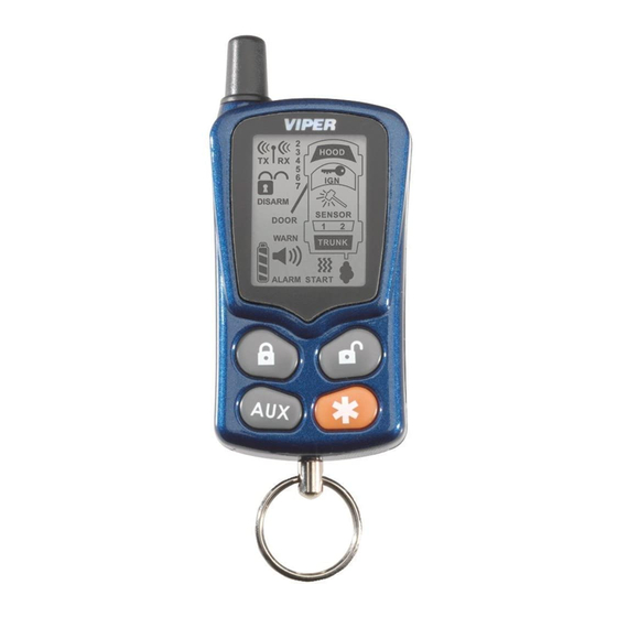
Page 31: Remote Control Diagram
© 2003 Directed Electronics, Inc. Vista, CA... -
Page 32: Standard Mode Configuration
18. Sensor 2 Indicator—Full Trigger and Warn Away® 19. Trunk Switch Input Indicator 20. Vibrate Mode Indicator 21. Remote Start Indicator 22. Disarm Button 23. Remote Start Button 24. Auxiliary Button 25. Arm Button © 2003 Directed Electronics, Inc. Vista, CA... -
Page 33: Operating Settings Learn Routine
LED OFF setting (or will flash two or more times for features with more than 2 settings). Release. The Valet®/Program switch can now tbe released. You can advance from feature to feature by pressing and releasing the Valet®/Program switch the number of times © 2003 Directed Electronics, Inc. Vista, CA... - Page 34 The ignition is turned on. The Valet/Program switch is pressed too many times. More than 15 seconds elapses between programming steps. One long horn honk (if connected) indicates that the Learn Routine has been exited. © 2003 Directed Electronics, Inc. Vista, CA...
-
Page 35: Feature Menus
Security features OFF (starter kill) 1-12 Code Hopping ON Code Hopping OFF 1-13 Channel 4 Validity Latched, Latch reset with ignition, 30-sec. timed *NOTE: The numbers in parentheses indicate the number of times the LED will flash. © 2003 Directed Electronics, Inc. Vista, CA... -
Page 36: Menu #2
Accessory state during wait to start ON 2-11 2nd status output NORMAL Rear defogger latch, rear defogger pulse 2-12 Anti-Grind ON Anti-Grind OFF *NOTE: The numbers in parentheses indicate the number of times the LED will flash. © 2003 Directed Electronics, Inc. Vista, CA... -
Page 37: Feature Descriptions
At the same time, the GREEN H4/1 wire will supply two positive pulses instead of a single pulse. This makes it possible to directly interface with double pulse vehicles without any extra parts. © 2003 Directed Electronics, Inc. Vista, CA... - Page 38 1-13 CHANNEL 4: This output can be programmed to produce a validity output that will stay active as long as the transmitter button assigned to that channel is pressed, a latched output, a latched output reset with igni- tion, or a 30-second timed output. © 2003 Directed Electronics, Inc. Vista, CA...
-
Page 39: Menu #2
2-8 ACTIVATION PULSE COUNT: This feature allows the number of pulses to activate the remote start feature to be changed from 1, 2, or 3 pulses. The pulse count programmed to start the vehicle will also be the same required to shut down the remote start. © 2003 Directed Electronics, Inc. Vista, CA... -
Page 40: Tach Learning
To learn the tach signal: Start the vehicle with the key. DRW-96 Within 5 seconds, press and HOLD the Valet/Program switch. The LED will light constant when the tach signal is learned. Release the Program switch. © 2003 Directed Electronics, Inc. Vista, CA... -
Page 41: Shutdown Diagnostics
Three Low or no RPM Four Transmitter Shutdown (or optional push-button) (+/-) Shutdown Seven (-) Neutral safety shutdown Eight Wait-to-start timed out The LED will stop flashing when the ignition is turned on. © 2003 Directed Electronics, Inc. Vista, CA... -
Page 42: Rapid Resume Logic
To exit timer mode, turn the ignition switch on any time the engine is running. The parking lights will flash 4 times, indicating timer mode has been exited. The system will start every 3 hours until canceled by the brake, hood, or neutral safety shut-down wires. © 2003 Directed Electronics, Inc. Vista, CA... -
Page 43: Valet Mode
Put the vehicle in Drive (D). e. Put your foot over the brake pedal but do not press down on it. Be ready to step on the brake to shut- down the remote start system. © 2003 Directed Electronics, Inc. Vista, CA... -
Page 44: Troubleshooting
2. Check voltage and fuses. Use a meter and check for voltage between the red wire in the 5 pin ribbon harness and the black ground wire. If you have less than battery voltage, check both 30A fuses on the relay satel- © 2003 Directed Electronics, Inc. Vista, CA... - Page 45 The vehicle will start and run only for about 10 seconds. 1. Is the remote start programmed for voltage sense? Try programming the unit for low voltage reference. If this does not work, a tach wire should be used. 2. Check diagnostics. © 2003 Directed Electronics, Inc. Vista, CA...
-
Page 46: Wiring Quick Reference Guide
© 2003 Directed Electronics, Inc. Vista, CA... -
Page 47: Relay Satellite Wiring Quick Reference Guide
© 2003 Directed Electronics, Inc. Vista, CA...
Need help?
Do you have a question about the 591XV and is the answer not in the manual?
Questions and answers