
Related Manuals for TeleEye RN284


Summary of Contents for TeleEye RN284
-
Page 1: User Manual
Installation & Safeguards User Manual Tele RN284 / RN288 / RN2816 Digital Video Recorder Before attempting to connect or operate this product, please read this manual carefully and keep it for future use. - Page 2 Notice: Signal Communications Limited reserves the right to make improvements to the product described in this manual at any time and without prior notice. This manual is copyrighted. All rights are reserved. This manual may not be copied, reproduced or translated in whole or part without prior consent from Signal Communications Limited.
- Page 3 INSTALLATION & SAFEGUARDS All the safety and operating instructions should be read before the unit is operated. Environment Condition for Installation To prevent electric shock or other hazard, do not expose units to rain, moisture, or dust. This unit should be located in an area with low humidity and a minimum of dust.. Place this unit in a well-ventilated place and do not place heat-generating objects on this unit.
-
Page 4: Table Of Contents
Contents Contents CHAP. 1 Features & Package Contents ---------------------------------------------------------------- 1-1. Features ---------------------------------------------------------------- 1-2. Package Contents ---------------------------------------------------------------- CHAP. 2 Function of Each Button ---------------------------------------------------------------- 2-1. Front ---------------------------------------------------------------- 2-2. Rear ---------------------------------------------------------------- CHAP. 3 Installation ---------------------------------------------------------------- 3-1. Installation Configuration ---------------------------------------------------------------- 3-2. Detailed Installation ---------------------------------------------------------------- HDD(Hard Disk Drive) ----------------------------------------------------------------... - Page 5 Contents 4-9. PTZ Camera Operation ---------------------------------------------------------------- 4-10. Data Back-Up ---------------------------------------------------------------- CHAP. 5 Set Up ---------------------------------------------------------------- 5-1. Entering the Menu ---------------------------------------------------------------- 5-2. Display Setup ---------------------------------------------------------------- Screen Display ---------------------------------------------------------------- Monitor Setup ---------------------------------------------------------------- 5-3. Configuration ---------------------------------------------------------------- HDD Management ---------------------------------------------------------------- TIME/DATE Setup ---------------------------------------------------------------- Camera Setup ---------------------------------------------------------------- Interval Setup ----------------------------------------------------------------...
-
Page 6: Chap. 1 Features & Package Contents
CHAP. 1 Features & Package Contents CHAP. 1 Features & Package Contents 1-1. Features Live View Real time display per camera Auto Sequence PIP (Picture in picture) Digital Zoom Display Freeze Simple Playback mode Simple PTZ camera control Record Variable Record resolution (For higher picture quality or higher recording speed) Efficient Image Quality setup in 5 steps Schedule Record / Holiday Record Event Record (Alarm / Motion) -
Page 7: Package Contents
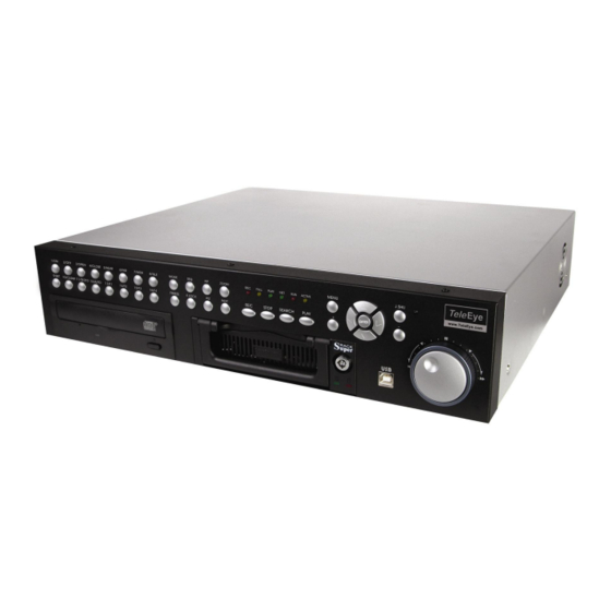
CHAP. 1 Features & Package Contents 1-2. Package Contents 2. Remote Controller 1. DVR Main Unit 3. Power Cable 6. Software CD 4. Power Adapter 5. User’s Manual 7. Battery for remote controller 8. Bolts Package Contents Description 1. DVR Main Unit STAND-ALONE DIGITAL VIDEO RECORDER 2. -
Page 8: Chap. 2 Function Of Each Button
CHAP. 2 Function of Each Button CHAP. 2 Function of Each Button 2-1 FRONT Name Function ① LED Lamps Shows status of operation ② USB Device Firmware upgrade by connecting PC with latest firmware to USB port ③ IR IR receiver ④... - Page 9 CHAP. 2 Function of Each Button Name Function 7. LIVE View On/Off for PAN/TILT/ZOOM control mode Control Press this button first to control PTZ camera connected to DVR unit via RS-485 ZOOM Zooming an image FREEZE Freezing an Image MODE Switch to split display MODE button changes screen-division from (to) full screen to (from) 4-split screen.
-
Page 10: Rear
CHAP. 2 Function of Each Button 2-2. REAR 4 Channel 8 Channel 16 Channel... -
Page 11: Chap.3 Installation
CHAP. 3 Installation Name Function RS 485 Connection with PTZ Camera or other external device using RS 485 interface (Pin 1: D- / Pin 2: D+) RELAY Output Relay out terminal SENSOR Input Sensor input terminal ETHERNET Connection to ETHERNET device RS-232C Connection to external device as PC using RS-232C to control the DVR CAMERA Input... -
Page 12: Detailed Installation
CHAP. 3 Installation 3-2. Detailed Installation 1) HDD 1. Connect Main Board and HDD using IDE cable and HDD power cable. 2. The jumper setting of HDD should be on Master if you install only one HDD. 3. The jumper setting of HDD1 should be on Master and HDD2 should be on Slave if you install two HDDs.(Refer to the above figure) 4. -
Page 13: Camera
CHAP. 3 Installation 2) Camera Connect cameras to the camera input on rear panel of DVR marked CAMERA IN. 3) Monitor Connect the video output marked MONITOR to Video In of Main monitor. 4) Power Insert the ADAPTER to the rear power socket of DVR. ADAPTER specification: Input AC 110~240V / Output DC12V 10A... -
Page 14: Vcr, Video Printer
CHAP. 3 Installation 5) VCR Connect VCR or VIDEO Printer to VCR out on the rear panel of DVR. 6) Other External Device SENSOR PAN/TILT CAMERA SIREN RS-232C : Control DVR through RS-232C port by using PC. RS-485 : Control external device like PTZ Camera (Pin 1, 2 at Terminal Block). RELAY Output : Relay Output (Pin 3 ~5 at Terminal Block). -
Page 15: Connector Pin Assignment
CHAP. 3 Installation 7) Connector Pin Assignment Description Description Data Carrier Detect Data Set Ready Receive data RS232C: Rx/Tx data Transmit data RS232C: Rx/Tx data Data Terminal data Signal Ground C o m m P o r t RS-232C 8) RS-232C ASCII-code Following ASCII-Codes(Hexa-Code) are for programmers who want to control DVR unit via the RS232C Port using keyboard of PC. -
Page 16: Chap.4 Operation
CHAP. 4 Operation CHAP.4 Operation 4-1. Start-up DVR Before turning on the DVR be sure that everything is firmly connected. Turn on the DVR and go to the Menu using the relevant Login Password and you will then see the System Setup Scree n. -
Page 17: Factory Default
CHAP 4. Operation 4-3. Factory Default Before initial configuring or operation you must first set Time/Date, followed by setting the unit to the FACTORY DEFAULT settings, lastly clearing the HDD. Please follow these steps in order. Improper operation may result if this action is not taken. 2. -
Page 18: Live View Setup
CHAP. 4 Operation 4-5. Live View Setup 1) Full / Multiple View Switch to multi-screen display by pressing [MODE]. For full image display, just press the channel button which you want or [MODE] button again. Full screen Full screen Multi-screen [MODE] or Channel button [MODE] 2) View in Sequence... -
Page 19: Record
CHAP. 4 Operation 4-6. Record Recording mode set before delivery by manufacturer (Default recording mode) is Schedule Recording. In this default recording mode, it records 24 hours/day continuously in weekday and on the weekend. Once you press the [REC] button while you see live view, the record type is changed to Emergency Record mode. - Emergency Record Record type : CONTINUOUS, SUPER FINE quality, Emergency Record [RED]... -
Page 20: Search
CHAP. 4 Operation 4-8. Search Press [SEARCH] button, and 3 different methods for searching recorded data are available as shown in following SEARCH window. For selecting searching method, use direction key or Jog/Shuttle. After selecting each search method, press [ENTER] button for playback. 1) SEARCH BAR Search by percentage of total recorded data. - Page 21 CHAP. 4 Operation 4-9. PAN/TILT/ZOOM Camera Operation Press [PTZ] button first for PTZ control mode. Numeric buttons from 1 to 16 and direction buttons are assigned for each PTZ command, and user can control PTZ camera connected to DVR unit by pressing any one of those 20 buttons, one after the other, as needed, and it is just like control by separate PTZ controller.
-
Page 22: Entering The Menu
CHAP. 5 Set Up CHAP. 5 Set Up 5-1. Entering into the Menu Enter into SYSTEM MENU by pressping [MENU] button. Button Function MENU Enter into SYSTEM MENU, Move to previous menu, ESC ENTER Selection key, Move to sub-menu, change status (ON or OFF) NEXT Move to next page Move to upper side... - Page 23 CHAP. 5 Set Up 5-2. DIPLAY SETUP Setting up parameters for monitor and display on screen. Enter into SYSTEM MENU-DIPLAY SETUP. DISPLAY SETUP LIVE SCREEN DISPLAY PLAYBACK MONITOR SETUP VGA SETUP(N/A in this version) COLOR BAR TEST SELECT MENU : ▲▼, & [ENTER] 1) SCREEN DISPLAY Setting up the screen display in LIVE mode and PLAYBACK mode.
-
Page 24: Configuration
CHAP. 5 Set Up 5-3. CONFIGURATION Various parameters for system can be set in CONFIGURATION menu. Enter into SYSTEM MENU-CONFIGURATION and press the [ENTER] button. CONFIGURATION HDD SETUP HDD MANAGEMENT HDD INFORMATION TIME/DATE SETUP CAMERA SETUP INTERVAL SETUP ALARM SETUP CAMERA TITLE BUZZER SETUP CAMERA SETTING... -
Page 25: Time/Date Setup
CHAP. 5 Set Up 2) TIME/DATE SETUP Set time and date of DVR system which is very TIME/DATE SETUP important for search with time and date of the event. YEAR Time and date set by manufacturer is different from local time of user, and user must set time and date MONTH 2005 / JUN /11 exactly in first operation. - Page 26 CHAP. 5 Set Up CAMERA ACTIVE SETUP MOTION SETUP CHANNEL STATUS LIVE --------------------------------------------------------------------------- SENSITIVITY GRADE ACTIVE MOTION DISPLAY TYPE ACTIVE LOSS RECORD DURATION 05 SEC ACTIVE SELECT ▲▼, PRESS ◀▶ SELECT : ▲▼, CHANGE VALUE : ◀▶ (3) CAMERA ACTIVE SETUP : With direction button, move to option to be changed, and press [ENTER] button to select [ON/OFF].
-
Page 27: Interval Setup
CHAP. 5 Set Up INTERVAL SETUP SWICHING INTERVAL 4) INTERVAL SETUP FULL SCREEN : 01 SEC Set the switching time interval for SEQ or PIP PIP SCREEN : 01 SEC function.(1 sec. ~ 99 sec.) EVENT RECORD FULL SCREEN : set the sequencing switch time interval EVENT UPDATE TIME : 01 SEC in live full screen. -
Page 28: Buzzer Setup
CHAP. 5 Set Up 6) BUZZER SETUP BUZZER SETUP Set parameters for buzzer (On or Off). Use direction button and [ENTER] button. KEY BEEP KEY BEEP : buzz when button is pressed. VIDEO LOSS VIDEO LOSS : buzz when video signal is lost. ALARM ACTIVE ALARM ACTIVE : buzz when alarm is activated. -
Page 29: Record Setup
CHAP. 5 Set Up 5-4. RECORD SETUP This is the most important configuration of the DVR. Enter into SYSTEM MENU-RECORD SETUP RECORD SETUP and press the [ENTER] button. RECORD CONFIGURATION 1) RECORD CONFIGURATION SCHEDULE SETUP HOLIDAY SETUP Use direction button to move and [ ] [+] button to set value. -
Page 30: Schedule Setup
CHAP. 5 Set Up 2) SCHEDULE SETUP Unless you selected other recording mode, DVR system records in Schedule Recording mode. In SCHEDULE REC SETUP, you set type of recording for every time interval of 2 hours in each day of the week. -
Page 31: Back-Up
CHAP. 5 Set Up 5-5. BACK-UP User can back up the recorded data to CD using CD writer installed in DVR. Refer to [START] and [END] of data on HDD and set copy from time, [START], and size of data copied, [SIZE], and move to BURN and press [ENTER] button to start copy. - Page 32 CHAP. 5 Set Up 1) TCP/IP SETUP TCP/IP function enables user to see live pictures and TCP/IP SETUP recorded pictures via the internet. To use the TCP/IP MAC ADDRESS 00-0A-A2-00-00-00 option, user must assign IP ADDRESS & GATEWAY IP ADDRESS 192.168.001.160 &...
-
Page 33: Factory Default
CHAP. 5 Set Up 5-7. FACTORY DEFAULT FACTORY DEFAULT Set the all system parameters as manufacturer first set before delivery. It is a kind of system SCREEN DISPLAY initialization, and manufacturer recommend to do it CAMERA COLOR SETUP when you add new HDD or other changes in MOTION SETUP system to make all system ready for normal PANTILT SERUP... -
Page 34: Chap. 6 Network Setup
CHAP. 6 Network Setup CHAP. 6 Network Setup 6-1. DVR Network Configuration Now that you are familiar with the equipment and should be able to identify a router from a modem and a Cat5 network cable from a telephone cable, we will proceed to determine the network scenario that fits your current network. - Page 35 CHAP. 6 Network Setup Case A : Single Static IP w/Personal Router Phone line Or CATV Personal Internet modem Router (ISP) w/switch Configure the DVR as follows : 1. Set the DVR to MANUAL for the TCP/IP settings. Do not use DHCP SETUP for this application or verify that DHCP SETUP is set to MANUAL.
- Page 36 CHAP. 6 Network Setup REMOTELY : To access the DVR remotely, that is from outside your local network, follow the above directions for accessing locally, except for the IP address. For CASE A, you have received a static IP from your Internet provider. That static IP address is what you must enter into the software for connectivity to take place(NOT the IP of the DVR).
- Page 37 CHAP. 6 Network Setup REMOTELY : To access the DVR remotely, open the remote viewing software and click on the “Settings” button. As far as TCP/IP connectivity is concerned only 4 entries need to be made : For CASE A, you have received a static IP from your Internet provider. That static IP address is what you must enter into the software for connectivity to take place(this should be the same IP address configured in the DVR).
- Page 38 CHAP. 6 Network Setup Accessing the DVR using the Remote Software for CASE C LOCALLY : To access the DVR locally, that is from your local network on site from where the DVR is installed. Open the remote viewing software and click on the “Settings” button. As far as TCP/IP connectivity is concerned only 4 entries need to be made : 1.
- Page 39 CHAP. 6 Network Setup 4. SUBNET MASK : 255.255.255.240 (example) a. Along with your static IP addresses you should have received your subnet mask from your Internet provider. Please use that subnet mask when configuring the DVR. If you did not receive this information contact your service provider. 5.
- Page 40 CHAP. 6 Network Setup Configure the DVR as follows : For this application you can still use the DVR for remote access, yet you will have to verify the IP address within the DVR on a continuous basis to ensure the IP address hasn’t changed.
-
Page 41: Remote Viewer Program
CHAP. 6 Network Setup 6-2. Remote Viewer program - Power switch : Press the Power switch to exit the program. Please disconnect the live feed before powering off the software - Connect button : Press the Connect button to view the live images from the DVR. These are the same images being displayed on the monitor of the DVR, with a delay depending on your internet connection at both the DVR location and from where you’re currently accessing. - Page 42 CHAP. 6 Network Setup Setting Screen Name: This just identifies your settings. The settings are automatically saved under this label when you hit ‘OK’. IP Address : Based on your network scenario and from where you’re accessing, enter the appropriate IP address.
- Page 43 CHAP. 6 Network Setup PLAYBACK INTERFACE Function of each button in Search window. Exit : Exit to live window. Full screen : Select a certain camera to view in full screen. Quad : To view quad mode (4 channels at the same time) Time : The recording time information of the pictures which is being played.
- Page 44 CHAP. 6 Network Setup : Play Fast backward : Move to the start of recording : Play backward(1X) : Move to the previous hour : Move to the previous hour : Play Forward(1X) : Play Fast Forward : Move to the end of recording : Stop playback * Speed of playback according to scan rate Scan rate...
- Page 45 CHAP. 6 Network Setup : Calendar Use this to select the date you wish to playback. The filled in square outlines the date that is at the beginning of the hard drives. The outlined square indicates the data at the end of the hard drives. Select the date you wish to view.
-
Page 46: Back-Up Cd Player
CHAP. 6 Network Setup 6-3. Back-up CD Player DVR units are with a built-in CD-RW, and user can copy images to CD.Using back-up CD player, user can see images on back-up CD, and function of each button in Back-up CD player is as below. 1. - Page 47 CHAP. 6 Network Setup Image EDIT 1. Image edit status window : Shows record time & date, Image size, Command status. 2. Function button a) Save : User can save an image in JPEG format. It is saved in the folder where you installed back-up CD player.
- Page 48 CHAP. 6 Network Setup 6 6 6 6 - - - - 4. 4. 4. 4. Frequently Asked Questions Frequently Asked Questions Frequently Asked Questions Frequently Asked Questions...
- Page 49 CHAP. 6 Network Setup...
- Page 50 CHAP. 6 Network Setup...
- Page 51 CHAP. 6 Network Setup...
- Page 52 CHAP. 6 Network Setup Can I configure my DVMR for remote access using a Dial Can I configure my DVMR for remote access using a Dial- - - - Up connection? Up connection? Can I configure my DVMR for remote access using a Dial Can I configure my DVMR for remote access using a Dial Up connection? Up connection?
-
Page 53: Chap. 7 Specifications
CHAP. 7 Specifications CHAP. 7 Specifications • The best picture quality in Playback(JPEG-2000) • Real time live display in all channels • 4/8/16 channel video 240(200)ips recording capability • Multi-language menu • Remote monitoring and download through network • Convenient search function with Jog-shuttle •...
Need help?
Do you have a question about the RN284 and is the answer not in the manual?
Questions and answers