Table of Contents
Advertisement
Advertisement
Table of Contents

Related Manuals for SportsArt Fitness E821


Summary of Contents for SportsArt Fitness E821
- Page 1 E821/E825/E830 Elliptical Trainer Repair Manual SPORTS ART INDUSTRIAL CO., LTD.
- Page 2 1-1-4. E821/E825/E830 Components - (1) Display Area 1-1-5. E821/E825/E830 Components - (2) Back Area Components 1-1-6. E821/E825/E830 Component Placement Illustrations – Display Area 1-1-7. E821/E825/E830 Component Placement Illustrations – Display Board Back 1-1-8. Electronic Component Illustrations – Drive Board 1-1-9. Electronic Component Illustrations - Other 2.
- Page 3 5-1-3. E821/E825/E830 Display Indicator LEDs 5-1-4. E821/E825/E830 Display Cable Connections 5-2-1. E821/E825/E830 Drive Board Operation Flow Chart 5-2-2. E821/E825/E830 Drive Board Indictor LED Placement and Definitions 5-2-3. E821/E825/E830 Drive Board Indicator LED Placement and Definitions 5-2-4. E821/E825/E830 Drive Board Wire Connection Placement and Definitions...
- Page 4 Repair Manual Table of Contents 6. Error Messages 6-1. ERR7 6-2. Unit Does Not Turn On 6-3. Key Malfunction 6-4. Telemetry Heart Rate Malfunction 6-5. HTR Heart Rate Malfunction 6-6. Resistance Malfunction 6-7. No Stride Operation 7. Electronic Component Testing 7-1.
- Page 5 Repair Manual Table of Contents 7-13. HTR Heart Rate Handlebar Test 7-14. Transformer Short/Open Test 7-15. Electro-Magnet Short/Open Test Mechanical Adjustments and Part Replacement 8-1. E821/E825/E830 Procedure to Remove Rear Covers...
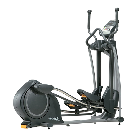
- Page 6 1.E821 Elliptical Trainer Unit Picture 1-1-1...
- Page 7 2.E825 Elliptical Trainer Unit Picture 1-1-2...
- Page 8 3.E830 Elliptical Trainer Unit Picture 1-1-3...
- Page 9 4.E821/E825/E830 Components (1) Display Area Display LEVEL Key STRIDE key (Not on E821) (Not on E821) HTR Contact (Left) HTR contact (Not on E821) (Right) (Not on E821) Stride Adjustment Motor 1-1-4...
- Page 10 5.E821/E825/E830 Components (2) Back Area Components Transformer Optic Sensor Drive Board Electro-magnet 1-1-5...
- Page 11 3.E821/E825/E830 Components – Display Board (Front) 1-1-6...
- Page 12 3.E821/E825/E830 E870 Components – Display Board (Back) 1-1-7...
- Page 13 3.E821/R825/R830 Components – Drive Board 1-1-8...
- Page 14 3.E821/E825/E830 Components - Others Part Name Optic Sensor Part Name HTR Board Part Name HRC Board Part Name Transformer 1-1-9...
- Page 15 1.E821/E825/E830 Specification Chart cification Contents E821 E825 E830 110V/220V RC window: 65%, 80%, Heartrate n Window orkout level, Calories , Time , Stride Length , 3.Di stance, Cal/HR, Strides/MIN, Total Strides Illus tration Window Bi-color LED dot matrix 16 set...
- Page 16 2.E821/E825/E830 Introduction – Display Windows Heart Rate Window 65% Target HR ÎActual heart rate ÎWeight loss target 80% Target HR Î Cardio training target heart rate heart rate Stride Length &Total Strides Dot Matrix Window ÎExercise illustrations Window Î Stride Length: Stride length ÎTotal Strides Total stride...
- Page 17 3. E821/E825/E830 Introduction – Display Keys and Indicators Flashing indicates heart rate reception Exercise Program Keys Î Lit indicates 2-1-3...
- Page 18 4.E821/E825/E830 Introduction – Display Keys (Continued) Quick Start Key ÎPress to operate in Quick Start Î mode (does not require user Exercise Program Keys ÎPress to select Display Lock/Unlock Key and exercise Indicator ÎPress to select active feedback Stride Length Key ÎPress to increase or...
- Page 19 E821/E825/E830 Operation 1. Start Up Function: Turn and start operating unit. Operation: (1) Turn on unit. Display shows “SPORTSART – E8XX”. After 6 seconds, “PRESS START” scrolls across the display. Press the QUICK START key to directly begin exercising, or press the PROGRAM key to establish user settings.
- Page 20 (2) Press the Stride Length < > key. The value in the Stride Length window decreases. The stride motor operates down. Stride length decreases. (3) Stride length range: E821/E825 KPH setting: 450-650 mm; MPH setting: 17~26 inches. E830 KPH setting: 450-730 mm; MPH setting: 17~29 inches.
- Page 21 5. Display Lock/Unlock Key Function: Toggle between two rows of exercise feedback information Operation: (1) Press the <Display Lock/Unlock> key during exercise to toggle between exercise feedback views. Corresponding indicators light. Top row: calories, distance, time, strides/minute. Bottom row: Cal/hr, stride length, Watts, total strides. (2) In scan mode (the SCAN indicator lights);...
- Page 22 7. Basic Settings Function: (1) KM/MILE setting, total distance, time, display and drive board versions. Operation: (1) Press and hold the <ENTER> key for three seconds to enter the setting mode. Unit settings appear. American standard appears as “UNIT - ML”. Metric standard appears as ”UNIT - KM”.
- Page 23 8. Stride Motor Lubrication Procedure Function: (1) Lubricate the stride motor. Operation: (1) As “SPORTSART-E8XX” scrolls across the display, simultaneously press and hold <STRIDE LENGTH >+<STRIDE LENGTH >+<INTERVAL> keys for three seconds to enter the lubrication procedure. (2) Upon entering the lubrication mode, the stride motor immediately operates, aligning itself with the oil hole.
- Page 24 1. E821/E825/E830 Display Board Cable Connection Block Diagram Resistance/ Stride Keys Telemetry Transmitter Display Board Stride Motor VR (E825/ (Left/Right) E830) Board HTR Contact (Left, Right) (E825/ E830) Drive Board 4-1-1...
- Page 25 2. E821/E825/E830 Drive Board Cable Connection Block Diagram Display Board Power On/Off Electro-Magnet Cord Switch FUSE Drive Board Optic Sensor Transformer Left Stride Right Stride Motor Motor 4-1-2...
- Page 26 1. E821/E825/E830 Display Board Wire Connections Resistance/ Stride Keypad POLAR Display Board Stride VR (Left/ (E825/ E830) Right) HTR Board HTR Grip (Left/ Right) (E825/ Drive Board E830) 5-1-1...
- Page 27 2. E821/E825/E830 Display Board Component Placement 5-1-2...
- Page 28 3. E821/E825/E830 Display Indicator LEDs LED2 5 VDC Indicator ÎLit = 5 VDC LED1 POWER Indicator ÎLit = Power Voltage LED27 NC Indicator ÎNot lit = Program Malfunction 5-1-3...
- Page 29 4. E821/E825/E830 Display Cable Connections CON1 ÎTo drive board CON3 ÎTo HRC board CON5 Î To stride VR (L&R) CON4 ÎTo resistance & stride keys CON2 Î To HTR board 5-1-4...
- Page 30 1. E821/E825/E830 Drive Board Operation Flow Chart Display Board Power On/Off Electro-magnet Cord Switch FUSE Drive Board Optic Sensor Transformer Left Stride Right Stride Motor Motor 5-1-1...
- Page 31 2. E821/E825/E830 Drive Board Indictor LED Placement and Definitions LED2 MOTOR Indicator LED12 CLK Indicator ÎLit = emitting voltage to ÎFlashing = optic sensor signal stride motor LED11 INCL_L_DN Indicator (GREEN) ÎLit = emitting voltage for stride motor to go down...
- Page 32 3. E821/E825/E830 Drive Board Indicator LED Placement and Definitions LED11 INCL_R_DN Indicator (GREEN) LED9 INCL_R_UP Indicator (RED) ÎLit = emitting voltage for stride motor to ÎLit = emitting voltage for stride go down motor to go up LED6 PWR_DN_L Indicator ÎExtinguishing = turning off stride motor voltage...
- Page 33 4. E821/E825/E830 Drive Board Wire Connection Placement and Definitions ÎTo transformer ÎTo left/right stride ÎTo electro-magnet and optic sensor ÎTo on/off switch ÎTo display board 5-2-4...
- Page 34 E821/E825/E830 Error Message: ERR 7 1. Definition: (1) The display CPU has not read the STRIDE VR1, VR2 voltage value. (2) Stride motor VR1, VR2 voltage exceeds the range of 0.5 to 4.5 VDC. 2. Block Diagram C O N...
-
Page 35: Troubleshooting
3. Operation Order Part Explanation Left/Right Stride Motor 1. STRIDE motor operates up or down. 8-PIN Cable 1. Voltage travels via the cable to the stride motor. Drive Board 1. Provides 22 VDC to the stride motors. 1. STRIDE setting travels the cable to the drive board. 16-PIN Cable 2. - Page 36 5. Troubleshooting Order Part Troubleshooting 1. When drive board LED8, LED10 lights but the left stride motor does not operate, inspect the left stride motor. When drive board LED9, LED11 lights and the right Left/Right Stride stride motor does not operate, inspect the right stride motor. Motor 2.
- Page 37 E821/E825/E830 Error Message: Unit Does Not Turn On 1. Circumstance of Malfunction: 1. Turn on unit on/off switch. Display does not beep. Display shows no reaction. 2. Block Diagram Power Cord Display Board On/Off Switch Drive Board Voltage Transformer 6-2-1...
- Page 38 3. Operation Step Part Explanation Power Cor 1. The pow cord provides power from the wall outlet. Fuse and Fu 1. The fuse protects the drive board. When current is too high, the fuse burns, Hold making an e ectrical open. Unit operation ends. 1.
- Page 39 4. Troubleshooting Troublesh ooting rd Plug 1. Inspec whether the power cord is plugged in properly. 1. Inspec t the fuse holder wire connections. Fuse and Fuse 2. Inspe t the householder spring connection. 3. I nspec t the fuse. 1.
- Page 40 E821/E825/E830 Error Message: Key Does Not Operate 1. Malfunction: (1) Turn on unit. Do not press any keys. Keys operate as if they had been pressed. (2) Press keys. Keys do not operate. There’s no reaction whatsoever. 2. Block Diagram...
- Page 41 3. Operation Explanation 1. Dis play CPU reads the key signal. Displ ay oard 2. Display operates. 4. Troubleshooting Troublesh ooting 1. Ins pect the key function of every PB point. Displ ay oard 2. Replac e the display as a test. 6-3-2...
- Page 42 E821/E825/E830 Error Message: Telemetry Heart Rate Malfunction 1. Circumstance of Malfunction: (1) No heart rate appears. (2) Heart rate value differs from actual heart rate. 2. Block Diagram Telemetry Telemetry Display Receiver Board Wireless HR 4-PIN Board Transmitter CON2 6-4-1...
- Page 43 3. Operation Part Operation Telem etry H 1. Tele metr y receiver detects heart rate and transmits the heart rate signal to the ansmitter receive r bo ard. Telemetry HR Receiver 1. The tel emetry receiver board receives the heart rate signal from the Board transmitter.
- Page 44 E825/E830 Error Message: HTR Heart Rate Malfunction 1. Circumstance of Malfunction: (1) Place both hands on the HTR contact pads. No heart rate value appears on the display. (2) Do not touch HTR contact pads. Display shows heart rate value. 2.
- Page 45 3. Operation Order Explanation andle 1. HTR ha dlebar contact pads detect the human heart rate. 2- N Cable 1. Left/rig handlebar HTR signals travel toward the display board. 5- N Cable 1. 2-pin c les connect to the 5-pin cable, which connects to the HTR board. 1.
- Page 46 4. Troubleshooting Order Troubles hooting Clean HTR contact pads on the handlebars. HTR Han dlebars 2. Test H TR cables. 2 IN Ca 1. Ins t cables and their connections. 5 IN Ca 1. Ins t cables and their connections. 1.
- Page 47 E821/E825/E830 Error Message: Resistance Malfunction 1. Circumstance of Malfunction: (1) Turn on unit. Exercise. Press LEVEL keys. Resistance is too high or too low. (2) Turn on unit. Resistance is too high. Pedals won’t move. 2. Block Diagram Display Board...
- Page 48 3. Operation Orde Explanati 1. In eration the electro-magnet produces magnetism, Elect ro- agnet causing re sistance on the flywheel. 2-PI N C ble 1. The ve board provides voltage to the electro-magnet. Optic en 1. Durin use, the optic sensor produces a CLK signal. 1.
- Page 49 4. Troubleshooting Orde Troubles hooting 1. In spec t whether there is resistance during operation. 2. Inspec t whether the electro-magnet is an electrical short or Elec agnet open. 3. Replac e the electro-magnet as a test. ble 1. Inspect the cable and its connections. 1.
-
Page 50: Block Diagram
E821/E825/E830 Error Message: No Stride Operation 1. Circumstance of Malfunction: Press Stride / key. Stride length on the display changes. Stride length does not change. 2. Block Diagram C O N D i s p l a y B o a r d... - Page 51 3. Operation Orde Part Explanation Strid Motor 1. Strid e motors operate up and down, changing the stride length. (Lef ght) 2. Mo or movement moves the VR, changing the VR output signal. 1. 22 DC travels the cable to the incline motor. 8 IN Cable 2.
- Page 52 4. Troubleshooting Orde Troubles hooting 1. In ct the cables and their connections. Stride M otor 2. Inspe ct whether the drive board provides voltage the stride rs after one presses stride keys. 3. Repl ce the stride motor as a test. 8- N C able 1.
- Page 53 E821/E825/E830 Optic Sensor Test 1. Test Configuration Fig. 1. Optic sensor/optic sticker distance Fig. 2. Optic sensor wire test Optic sensor sticker Black 7~8 mm Yellow Infrared sensor Optic sensor board Optic sensor bracket screws are in the middle of the bracket.
- Page 54 2. Test Configuration (1) Optic sensor/optic sensor sticker distance test Inspect the distance from the infrared optic sensor board to the optic sensor sticker. Normal distance: 7-8 . See illustration. (2) Optic sensor signal test Put voltmeter to the 20 VDC setting. Probes as shown. Operate unit. See Fig. 2 for normal readings.
- Page 55 E821/E825/E830 Transformer Test at Drive Board 1. Test Configuration CN1 transformer connection LED2 stride motor LED1 VDD LED7 VCC 7-2-1...
- Page 56 2. Test Procedure 1. Connect the transformer to the drive board CN1 connector. 2. Set voltmeter to the 200 VAC (or 6000 VAC) setting. 3. Turn on power. Insert meter probes separately to contact both red wire (blue wire in 220V markets) pins as shown.
- Page 57 E821/E825/E830 Drive Board Stride Motor Voltage Test 1. Test Configuration Motor power test LED2 Stride motor indicator hoop Ground terminal 7-3-1...
- Page 58 2. Test Procedure (1) Put voltmeter to the 200 VDC setting. Place meter probes separately on the MOTOR POWER and GND hoops on the drive board. (2) Normal reading: 22±0.1VDC. (3) If the drive board is not emitting any voltage, the stride motor will not operate. Black probe on the GND test hoop Red probe on MOTOR POWER hoop Voltage reading 3.
- Page 59 E821/E825/E830 Drive Board VCC Voltage Test 1. Test Configuration VCC hoop LED7 VCC LED GND hoop 7-4-1...
- Page 60 2. Test Procedure (1) Put the voltmeter at the 20 VDC setting. Place proves separately on the VCC and GND test hoops on the drive board. (2) Normal reading: 5±0.1 VDC. Black probe on GND test hoop Red probe on VCC test hoop Normal reading 3.
- Page 61 E821/E825/E830 Drive Board VDD Voltage Test 1. Test Configuration LED1 VDD VDD hoop GND1 hoop 7-5-1...
- Page 62 2. Test Procedure (1) Put voltmeter to the 200 VDC setting. Place probes separately on VDD and GND1 hoops. (2) Normal reading: 30~31 VDC. Black probe on GND1 terminal; Red probe on VDD. Normal reading is shown below. 3. Troubleshooting (1) If there is no resistance, inspect the following: a.
- Page 63 E821/E825/E830 Electro-Magnet Voltage Test at Drive Board 1. Test Configuration LED1 VDD GND1 hoop VPP hoop 7-6-1...
- Page 64 2. Test Procedure (1) Put voltmeter to the 200 VDC setting. Place probes separately on VPP and GND1 hoops on the drive board. (2) Normal reading: 28±0.1 VDC. Block probe on GND1 hoop. Red probe on VPP hoop. Normal reading. 3.
- Page 65 Keypad Test 1.Test Configuration 7-7-1...
- Page 66 2.Test Procedure (1) Put the voltmeter to the 200 ohm setting. Place probes separately on key switch points A and B. (2) Do not press any keys. Voltmeter shows no reaction: OL (open line). (3) Press a key. Voltmeter shows 0 ohm. 3.Circumstance of Malfunction (1) If the key is not pressed and the voltmeter shows 0 ohm, the key switch has a permanent electrical short.
- Page 67 E821/E825/E830 VBB Voltage Test at the Display 1.Test Configuration LED2 LED1 7-8-1...
- Page 68 2. Test Procedure (1) Turn on unit power. LED1 and LED2 on the display light up. (2)Put voltmeter to the 20 VDC or higher setting. Place probes as shown in the test configuration diagram. (3) Normal reading: 12 VDC ±0.3 VDC. 3.
- Page 69 E821/E825/E830 VCC Voltage Test at the Display 1.Test Configuration LED1 LED27 7-9-1...
- Page 70 2. Test Procedure (1) Turn on unit power. LED1 and LED27 on the display board light. (2) Put voltmeter to the 20 VDC setting. Place probes as shown. (3) Normal reading: 5 VDC ±0.2 VDC. (4) Display beeps once and LEDs light up. 3.
- Page 71 E821/E825/E830 Display LED Voltage Test 1.Test Configuration LED2 7-10-1...
- Page 72 2. Test Procedure 1. Turn on unit power. LED2 on the display lights up. 2. Put voltmeter to the 20 VDC or higher setting. Place probes as shown.l 3. Normal reading: 5 VDC ±0.2 VDC. 4. Display beeps once and LEDs light up. 3.
- Page 73 E821/E825/E830 Telemetry Heart Rate Receiver Board Test 1. Test Configuration Heart rate window Heart rate transmitter 7-11-1...
- Page 74 2. Test Procedure (1) Put on the heart rate telemetry strap. (2) Press the Quick Start key and start exercising. (3) Display shows heart rate in the heart rate window. 3. Troubleshooting If there is no heart rate reading, inspect the following. (1) Make sure the telemetry strap is connected and worn properly.
- Page 75 E825/E830 Heart Touch Rate (HTR) Board Test 1. HTR board LED placement and definitions LED3 LED4 LED2 LED1 LED Definitions LED# Color Name Explanation LED1 Telemetry signal Flashing indicates reception of telemetry signal LED2 Orange HTR grip signal Lit indicates contact made to HTR grips LED3 Green Incoming HR signal Flashing indicates reception of incoming...
- Page 76 2. Test Procedure The following test results indicate normal operation. 1. No LEDs on the HTR board light when you don’t contact the HTR grips. 2. When you contact the HTR grips with both hands, LED2 indicators light. 3. When LED3 flashes, an incoming heart rate signal is being received. 4.
- Page 77 HTR Cable (2-pin to HTR Left and Right Contacts) Test Fig. 1: Place black probe as indicated Fig. 2: Place red probe as indicated on HTR contacts (Note: There are three wires on the HTR board 2-pin cable.) 7-13-1...
- Page 78 2. Test Procedure (1) Do not turn on unit power. Remove display cover to access the HTR board 5-pin cable. (2) Put voltmeter to the 200 ohm setting. Place probes as shown in Fig. 1 and 2. Test HTR cable and ground for electrical shorts and opens. (3) Test as shown below.
- Page 79 E821/E825/E830 Transformer Electrical Short/Open Test 1.Test Configuration Fig.1 Electrical Open Test Fig. 2. Electrical Short Test 7-14-1...
- Page 80 2. Test Procedure (1) Electrical Open Test: Set voltmeter to the 200 setting. Test common colored wires. See Fig. 1. Normal reading: <20 . (2) Electrical Short Test: Set voltmeter to the 20 M setting. Test differently colored wires. See Fig. 2. Normal reading: ’, OL. Normal Test Point Value...
- Page 81 E821/E825/E830 Electro-Magnet Electrical Open or Short Test 1.Test Configuration Fig. 1: Electrical OpenTest Fig. 2: Electrical Short Test Wire-to-Cover Electrical Short Test 7-15-1...
- Page 82 2. Test Procedure (1) Electrical open test: Put voltmeter to the 200 setting. Place probes as shown in Fig. 1. Normal test results are shown below. Note: a reading of just under 20 indicates the electro-magnet is OK. (2) Electrical short test: Put voltmeter to the 20 M setting. Place probes as shown in Fig. 2. Normal test results are shown below.
- Page 83 E821/E825/E830 Procedure to Remove Rear Covers 5. Remove upper cover. 6. Remove L/R rear covers. 1. Remove L/R glide rail covers. 2. Remove the screw cover strip. 3. Remove the rotating cover. 4. Remove cover screws. 8-1-1...
- Page 84 1. Use a Phillips head screwdriver to remove three 2. Disconnect cover B from cover A. Remove cover A. crews from glide rail cover B. Cover A Cover B 3. Remove cover B by pushing inward and 4. Rotate cover B downward to remove it. downward.
- Page 85 5. Use a flat-head screwdriver to pry up the screw 6. Gently pry up the screw cover strip. cover strip. 7. Locate screws on the rotating cover. 8. Use a Phillips head screwdriver to remove the screws on the rotating cover. 8-1-3...
- Page 86 9. Put the glide rail into the position shown. Pull the 10. Locate screws on left and right sides. Circled rotating cover downward to remove it. screw is accessed from one side only. 11. Use a Phillips head screwdriver to remove these 12.
- Page 87 13. After removing screws, covers can be moved 14. To remove covers, use an M6 Allen wrench to forward, allowing access for some jobs. remove the glide rail screw. 15. This illustration shows covers totally removed. 16.Covers can be assembled in the same order they were removed.
Need help?
Do you have a question about the E821 and is the answer not in the manual?
Questions and answers