
Related Manuals for Husqvarna WG3213P/968999114


Summary of Contents for Husqvarna WG3213P/968999114
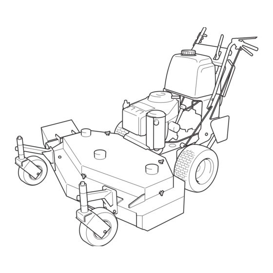
- Page 1 Operator's manual WG4815P/968999278 WG3613P/968999116 WG3213P/968999114 Please read the operator’s manual carefully and make sure you English understand the instructions before using the machine.
-
Page 3: Table Of Contents
OPERATOR’S MANUAL WG3213P WG3613P WG4815P Contents Contents... 1 Introduction ... 3 Congratulations... 3 General ... 3 Driving and Transport on Public Roads ... 3 Towing ... 3 Operating ... 3 Good Service ... 4 Manufacturing Number ... 4 Symbols and Decals ... 5 Safety Instructions... - Page 4 WARNING! Failure to follow cautious operating practices can result in serious injury to the operator or other persons. The owner must understand these instructions, and must allow only trained persons who understand these instructions to operate the mower. Each person operating the mower must be of sound mind and body and must not be under the influence of any mind altering substance.
-
Page 5: Introduction
Introduction Congratulations Thank you for purchasing a Husqvarna Walk-Behind Mower. This machine is built for the greatest efficiency and rapid mowing primarily of large areas. Controls in one place and a transmission regulated by motion controls contribute to the machine’s performance. -
Page 6: Good Service
Good Service Husqvarna’s products are sold all over the world and only in specialized retail stores with complete service. This ensures that you as a customer receive only the best support and service. Before the product is delivered, the machine has, for example, been inspected and adjusted by your retailer, see the certificate in the Service Journal in this Operator’s Manual. -
Page 7: Symbols And Decals
SYMBOLS AND DECALS Symbols and Decals These symbols are found on the machine and in the operator’s manual. Study them carefully so that you know what they mean. WARNING! Xxxxxxx xxxx xxxxxxxx xxx x Xxxxx xxxxxx xx. xx xxxxxxxx xxxxx xxx xx. Used in this publication to notify the reader of a risk of personal injury, particularly if the reader should neglect to follow instructions given in the manual. - Page 8 SYMBOLS AND DECALS Keep a safe distance from the machine. Moving sharp blades Read under cover. Operator´s Manual. Whole body exposure to thrown objects. English- Severing of fingers & toes. Rotating blades. Shut off engine & remove key before performing any maintenance or repair work.
-
Page 9: Safety Instructions
SAFETY INSTRUCTIONS Safety Instructions These instructions are for your safety. Read them carefully. WARNING! This symbol means that important safety instructions need to be emphasized. It concerns your safety. General Use • Read all instructions in this operator’s manual and on the machine before starting it. - Page 10 SAFETY INSTRUCTIONS • Shut off the blades when not mowing. • Be careful when turning around fixed objects, so that the blades do not hit them. Never drive over foreign objects. • Only use the machine in daylight or in other well-lit conditions.
-
Page 11: Driving On Slopes
SAFETY INSTRUCTIONS Driving on Slopes Driving on slopes is one of the operations where the risk is greatest that the driver will lose control or the machine will tip over, which can result in serious injury or death. All slopes require extra caution. If you cannot reverse up a slope or if you feel unsure, do not mow the slope. -
Page 12: Children
SAFETY INSTRUCTIONS Children • Serious accidents may occur if you fail to be on guard for children in the vicinity of the machine. Children are often attracted to the machine and mowing work. Never assume that children will stay where you last saw them. -
Page 13: Maintenance
SAFETY INSTRUCTIONS Maintenance WARNING! The engine must not be started when the protective plate for the mower deck’s drive belt is removed. • Stop the engine. Prevent the engine from starting by removing the spark plug cables from the spark plugs or by removing the ignition key before making any adjustments or performing maintenance. - Page 14 • Safety decals should be replaced if they are missing or illegible. Decals can be purchased from your Husqvarna dealer. English- Use protective glasses at maintenance work. Never drive the machine in an enclosed space...
-
Page 15: Transport
(if any). If a spark arrester is used, it should be maintained in effective working order by the operator. A spark arrester for the muffler is available through your authorized Husqvarna dealer. IMPORTANT INFORMATION The parking brake is not sufficient to lock the machine in place during transport. -
Page 16: Controls
Controls This operator’s manual describes the Husqvarna Walk-Behind Mowers WG3213P, WG3613P and WG4815P. The machines are fitted with a Kawasaki or Kohler four-stroke V- Twin engine, for data see “Technical data” on page 60. Transmission from the engine is made via two V-belts, one for each wheel. -
Page 17: Recoil Starter Grip
Pull the recoil starter grip slowly until you feel compresion, then pull it briskly. Normally this engine will not backfire. If you get backfires, contact your Husqvarna dealer for service. 2. Ignition Switch The ignition key switch is placed on the control panel. -
Page 18: Motion Control Levers
3. Motion control levers The machine’s speed and direction are continuously variable using the two motion control levers. When both controls are in the neutral position, the machine stands still. The controls can be locked in neutral position by the thumb latches. By releasing both controls an equal amount, the machine moves in a straight line forward. -
Page 19: Choke And Throttle Control
CONTROLS 5. Choke and Throttle Control Choke Control The choke control is combined with the throttle control. To engage the choke, the throttle control is moved past the max rpm setting to its choke position. Do not use the choke when starting a warm engine. -
Page 20: Thumb Latch
7. Thumb Latch The thumb latches are used to lock the motion control levers in their neutral position e.g. when starting the engine. Lock the motion control levers by pulling the thumb latches backward. Unlock the motion control levers by pushing the thumb latches forward. -
Page 21: Refueling
9. Refueling The machine has one fuel tank. The tank volume is 5.3 Gallons / 20 liters. The engine should be run on a minimum of 87-octane unleaded gasoline (no oil mix). See “Technical data” on page 60 concerning methanol and ethanol fuels. WARNING! Gasoline is highly flammable. -
Page 22: Fuel Shut-Off Valve
10. Fuel Shut-off Valve The fuel shut-off valve is placed on the fuel line below the fuel tank. The valve has two positions; ON and OFF. The figure shows the valve in the closed OFF position. IMPORTANT INFORMATION Close fuel valve at the end of each mowing job. -
Page 23: Operation
Operation WARNING! Be thoroughly familiar with all controls, their function and how to operate them before operating the mower. Before Starting • Read the sections “Safety Instructions” on page 7, and “Controls” on page 14, before starting the machine. • Perform the daily maintenance before starting (see “Maintenance Schedule”... -
Page 24: Starting The Engine
Starting the Engine WARNING! Never run the engine indoors, in enclosed or poorly ventilated spaces. Engine exhaust fumes contain poisonous carbon monoxide. Move blade engagement lever to the OFF position, so the interlock will allow engine to start. Check gear shifter to be sure it is in the neutral position. - Page 25 Open fuel shut-off valve. Turn ignition key to ON position. Set throttle control and engage the choke (if needed). Do not use choke when the engine is warm. OPERATION Fuel shut-off valve, Open Ignition key Choke and Throttle control 8011-438 8011-693 8011-709 English-...
- Page 26 IMPORTANT INFORMATION Do not let recoil cord snap back by itself. This may damage the cord or the recoil starter assembly. Pull the recoil starter grip slowly until you feel compression, then pull it briskly. If the engine won´t start in three pulls, open the choke and try again.
-
Page 27: Gearbox
Gearbox The gear drive machines have a 5-speed gearbox. The gear shift lever is placed below the control panel. Only shift gear when the machine is standing still and on level ground. Running IMPORTANT INFORMATION At least one of the Operator Presence Levers must be held in, otherwise the engine will stop. -
Page 28: Reversing
Reversing Depress one operator presence lever and shift transmission to the reverse gear. Grip both motion control levers before shifting gear. To operate on hills To operate on slopes is a dangerous mowing job. Read the Safety Instructions section “Driving on Slopes” on page 9. WARNING! not drive up or down hills with slopes greater than 10... -
Page 29: Mowing Tips
Mowing Tips • Observe and mark rocks and other fixed objects in order to avoid collisions. • The cutting deck should be properly leveled for best mowing performance. The blades should be parallel to the ground or slightly tipped down in the front. - Page 30 • Avoid mowing wet lawns. The mowing result is poorer because the wheels sink into the soft lawn, clumps build, and the grass clippings will fasten under the cowling. • Hose the mower deck with water after each use. Hose especially underneath. Do not spray high pressure spray directly on top of spindles.
-
Page 31: Stopping
Stopping Emergency stop Release both hands from the operator presence lever handles. When both operator presence levers return to their outer position, the engine will quit and the mower will stop. Pull both motion control levers firmly against handle grips and hold them securely in place. Use thumb latches to lock both motion control levers in neutral positions. -
Page 32: Stopping The Engine
Stopping the Engine Allow the engine to idle a minute in order to attain normal operating temperature before stopping it, if it has been worked hard. Avoid idling the engine for longer periods, as there is a risk of the spark plugs fouling. When the machine is standing still, activate the parking brake by moving the thumb latches to the park brake position. -
Page 33: Adjustment Of Cutting Height
Adjustment of cutting height The cutting height can be adjusted by three methods: • Moving spacers between the upper side and the lower side of the caster swivel according to "Cutting height table". For instruction, see below. • Moving spacers between the upper side and the lower side of the blades according to "Cutting height table". - Page 34 Cutting height table Spacers Axle below position caster arm English- OPERATION Blade spacers Cutting under cutter height housing 1 1/2" (38 1 3/4" (44 2" (51 mm) 2 1/4" (57 2 1/2" (64 1 3/4" (44 2" (51 mm) 2 1/4" (57 2 1/2"...
- Page 35 Spacers Axle below position under cutter caster arm OPERATION Blade spacers Cutting height housing 3 1/4" (83 3 1/2" (89 3 3/4 (95 4" (102 mm) 4 1/4" (108 3 1/2" (89 3 3/4" (95 4" (102 mm) 4 1/4" (108 4 1/2"...
-
Page 36: Moving Machine By Hand
OPERATION Moving Machine by Hand In order for the machine to be moved with the engine turned off, make sure the gear shift lever is in neutral position. Release the parking brake. 8011-482 Gear shift lever in neutral position English-... -
Page 37: Maintenance
Maintenance Maintenance Schedule The following is a list of maintenance procedures that must be performed on the machine. For those points not described in this manual, visit an authorized service workshop. An annual service carried out by an authorized service workshop is recommended in order to maintain your machine in the best possible condition and to ensure safe operation. - Page 38 Maintenance Check/adjust the cutting height Linkages and adjustments Check throttle and choke cables Clean the air cleaner’s pre-filter (foam) Clean the air cleaner’s filter cartridge (paper filter) Change the engine oil Replace the engine oil filter (every 200 hours) Clean/Replace the spark plugs Replace the fuel filter Clean the cooling fins Check the engine valve clearance...
-
Page 39: Ignition System
Ignition System The engine is equipped with an electronic ignition system. Only the spark plugs require maintenance. For recommended spark plugs, see Technical Data. Remove the ignition cable boot and clean around the spark plug. Remove the spark plugs with a spark plug socket wrench. -
Page 40: Checking The Safety System
Checking the Safety System The machine is equipped with a safety system that prevents starting or driving under the following conditions. The engine can only be started when: The blades are disengaged. The motion control levers must be in the locked position. -
Page 41: Checking And Adjusting The Throttle Cable And The Choke Cable
Check that the engine responds to throttle increases and that a good engine speed is attained at full throttle. If doubts arise, contact the Husqvarna service workshop. If adjustments are necessary, they can be made as follows for the cable: Loosen the clamping screw for the cable’s outer casing. -
Page 42: Kawasaki Engine Air Filter
Kawasaki Engine Air Filter If the engine seems weak or runs unevenly, the air filter may be clogged. If run with a dirty air filter, the spark plugs can become fouled and disrupt operation. For this reason, it is important to replace the air filter regularly (see the heading Maintenance Schedule for the proper service interval). -
Page 43: Kohler Engine Air Filter
Kohler Engine Air Filter If the engine seems to lack power or runs rough the reason may be that the air filter is clogged. It is therefore important to service the air filter at regular intervals (see “Maintenance Schedule” on page 35 for correct service interval). -
Page 44: Replacing The Fuel Filter
Replacing the Fuel Filter Replace the line-mounted fuel filter every 100 hours (once per season) or more regularly if it is clogged. Replace the filter as follows: Move the hose clamps away from the filter. Use flat-nosed pliers. Pull the filter loose from the hose ends. Push the new filter into the hose ends. -
Page 45: Checking The Parking Brake
Checking the Parking Brake Visually check that no damage is found on the thumb latches. Perform a test drive and check that there is a sufficent braking action. To adjust the brake, contact the service workshop if you are uncertain. Set the thumb latches in the neutral locked position. -
Page 46: Checking The Blades
Checking the Blades In order to attain the best mowing effect, it is important that the blades are well sharpened and not damaged. Bent or cracked blades or blades with large nicks must be replaced. Check the blade mounts. IMPORTANT INFORMATION The replacement or sharpening of blades should be carried out by an authorized service workshop. -
Page 47: Cleaning And Washing
Cleaning and Washing Regular cleaning and washing, especially under the mower deck, will increase the machine’s lifespan. Make it a habit to clean the machine directly after use, before the dirt sticks. Do not spray high pressure water directly on the top of the deck. Caster Wheels Check every 200 hours. -
Page 48: Blade Replacement
• Install and tighten blade bolt securely. Tightening torque 90 ft/lb (122 Nm). IMPORTANT INFORMATION Special blade bolt is heat treated. Replace with a Husqvarna bolt if required. Do NOT use lower grade hardware than specified. English- MAINTENANCE Blade Center hole... -
Page 49: Lubrication
Lubrication Lubrication Schedule 12/12 1/52 1/365 Lubrication schedule 12/12 Every year Lubricate with grease gun 1/52 Every week 1/365 Every day General Remove the ignition key to prevent unintentional movements during lubrication. When lubricating with an oil can, it should be filled with engine oil. When lubricating with grease, unless otherwise stated, with a high grade molybdenum disulfide grease or another chassis or ball bearing grease offering good corrosion protection should be used. -
Page 50: Lubricating The Cables
LUBRICATION Lubricating the Cables If possible, lubricate both ends of the cables and move the controls to end stop positions when lubricating. Refit the rubber covers on the cables after lubrication. Cables with sheaths will bind if they are not lubricated regularly. - Page 51 4. Changing the Oil Filter Drain the engine oil in accordance with the description under the heading Engine Oil/Change Engine Oil. On Kohler engine, drain the filter by the plug at the filter base before removal. Remove the oil filter. If necessary, use a filter remover.
- Page 52 5. Engine oil Kawasaki Engine Changing the Engine Oil The engine oil should be changed for the first time after 8 hours of operation. Thereafter, it should be changed every 100 hours. WARNING! Engine oil can be very hot if it is drained directly after stopping the engine.
- Page 53 LUBRICATION The oil level should lie between the markings on the dipstick. If the level is approaching the ”ADD” mark, fill the oil to the ”FULL” mark on the dipstick. Never fill above the ”FULL” mark. The oil is filled through the hole for the dipstick.
- Page 54 Kohler Engine Changing the Engine Oil Change oil after every 100 hours of operation (more frequently under severe conditions). Refill with service class SG, SH, SJ or higher oil as specified in the Viscosity Grades table on page 54. Change the oil while the engine is still warm. The oil will flow more freely and carry away more impurities.
- Page 55 Checking the Oil Level The importance of checking and maintaining the proper oil level in the crankcase cannot be overemphasized. Check oil before each use as follows: Make sure the engine is stopped, level, and is cool so the oil has had time to drain into the oil pan.
- Page 56 Oil Recommendations Using the proper type and weight of oil in the crankcase is extremely important. So is checking oil daily and changing oil regularly. Failure to use the correct oil, or using dirty oil, causes premature engine wear and failure. Oil Type Use high quality detergent oil of API (American Petroleum Institute) service class...
- Page 57 LUBRICATION 6. Mower deck lever Lubricate with a grease gun, one zerk, until the grease is forced out. Use only good quality molybdenum disulphide grease. Grease from well-known brand names (petrochemical companies, etc.) usually maintains a good quality. 8011-715 Lubricating deck lever 7.
- Page 58 9. Rear wheels Lubricate with a grease gun, one zerk for each wheel, until the grease is forced out. Use only good quality molybdenum disulphide grease. Grease from well-known brand names (petrochemical companies, etc.) usually maintains a good quality. IMPORTANT INFORMATION Be spartan and remove excess lubricant so that is does not come into contact with belts.
-
Page 59: Trouble Shooting Guide
TROUBLE SHOOTING GUIDE Trouble Shooting Guide Problem The engine will not start. The engine runs unevenly. The engine seems weak. Cause • The control for engaging the mower deck is in engaged position. • The motion controls are not locked in the neutral position. - Page 60 TROUBLE SHOOTING GUIDE The engine overheats. The machine moves slowly, unevenly, Mower deck not engaging. Uneven mowing results. The machine vibrates. The machine moves when in neutral postion. The machine pulls left or right. English- • Clogged air intake or cooling fins. •...
-
Page 61: Storage
Service When ordering spare parts, please specify the purchase year, model, type, and serial number. Always use genuine Husqvarna spare parts. An annual check-up at an authorized service workshop is a good way to ensure that your machine performs its best the following season. -
Page 62: Technical Data
Technical data WG3213P Engine Manufacturer Kohler Type CV13 Power 13 hp / 9.5 kW Spark plugs / gap Champion RC12YC .030” / 0.75 mm Oil capacity excl filter 1.9 qt. / 1.8 liters Oil capacity incl filter 2 qt. / 1.9 liters Engine oil SAE 10W30 API (See viscocity digram) - Page 63 WG3213P Productivity Productivity 1.6 acres/h / 6480 Overall dimensions Weight 370 lbs / 168 kg Base maschine lenght 66” / 168 cm Base machine width 37” / 94 cm Base machine height 42” / 106 cm Overall width, Chute up 33”...
-
Page 64: Torque Specifications
Torque Specifications Engine crankshaft bolt Deck pulley bolts Blade bolt Standard ¼” fasteners Standard 5/16” fasteners Standard 3/8” fasteners Standard 7/16” fasteners Standard ½” fasteners When this product is worn out and no longer used, it should be returned to the dealer or other party for recycling. -
Page 65: Wiring Diagram
WIRING DIAGRAMS Wiring diagram 8011-695 English-... -
Page 66: Conformity Certificates
CONFORMITY CERTIFICATES Conformity Certificates USA requirements Labels are placed on the engine and/or in the engine compartment stating that the machine will fulfill the requirements. This is also applicable to special requirements for any of the states, (Californian emission rules etc.). Do not remove any of these labels. Certificates can also be supplied with the machine at delivery or written in the Engine manual. -
Page 67: Service Journal
Service Journal Action Delivery Service Mount the caster wheels. Adjust the tire pressure of all wheels to 1 bar (15 PSI). Check that the right amount of oil is in the engine. Adjust the position of the motion controls. Fill with fuel and open the fuel tap. Start the engine. -
Page 68: 25-Hour Service
Action 25-Hour Service Check the fuel pump’s air filter (Kawasaki engine). Check the tire pressures and tire damage. Check/clean the engine’s cooling air intake. Clean the air cleaner’s pre-filter (foam). Check the cutting deck. English- SERVICE JOURNAL Date, mtr reading, stamp, sign... -
Page 69: 50-Hour Service
SERVICE JOURNAL Action 50-Hour Service Perform the 25-hour service. Clean/replace the air cleaner’s filter cartridge (paper filter) (shorter intervals for dusty operating conditions). Lubricate the front wheel bearings. Lubricate the throttle/choke cable. Check/adjust the parking brake. Date, mtr reading, stamp, sign English-... -
Page 70: 100-Hour Service
Action 100-Hour Service Perform the 25-hour service. Perform the 50-hour service. Change engine oil. Check whether the engine oil filter needs changing (every 200 hours). Clean/replace the spark plugs. Replace the fuel filter. Clean the cooling fins on the engine and transmission. Check V-belts, pulleys etc. -
Page 71: 300-Hour Service
SERVICE JOURNAL Action 300-Hour Service Inspect the machine. Come to agreement with the customer as to which additional work is to be carried out. Perform the 25-hour service. Perform the 50-hour service. Perform the 100-hour service. Clean the combustion chamber and grind the valve seats. Check the engine valve clearance. -
Page 72: At Least Once Each Year
Action At Least Once Each Year Clean the engine’s cooling air intake (25 hours). Replace the air cleaner’s pre-filter (Oil-foam) (300 hours). Replace the air filter’s paper cartridge (200 hours). Change the engine oil (100 hours). Replace the engine oil filter (200 hours). Check/adjust the cutting height. - Page 73 SERVICE JOURNAL Action Date, mtr reading, stamp, sign English-...
- Page 74 106471R04 08/11/05...
Need help?
Do you have a question about the WG3213P/968999114 and is the answer not in the manual?
Questions and answers