
Related Manuals for Husqvarna W3613ETS, W4815ETS


Summary of Contents for Husqvarna W3613ETS, W4815ETS
-
Page 1: Operators Manual
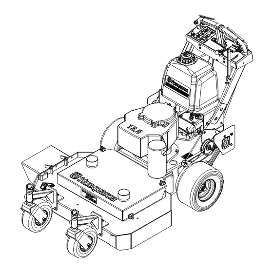
Operators Manual Models: 968999117 / W3613ETS 968999120 / W4815ETS Please read these instructions carefully and make sure you understand them before using the machine. MANUAL NO. 539106457 REV. IR (09/20/01) -
Page 2: Technical Assistance
INSTRUCTIONS AND COMMON SENSE. INTRODUCTION This manual has been prepared for the operators of the HUSQVARNA 36" and 48" commercial mowers. Read, understand, and follow the safety and operating instructions. Always stop the engine and blades, place the traction levers in drive, and place the mower in gear when leaving unattended. - Page 3 Table of Contents SAFETY ... 4 SETUP AND ADJUSTMENTS ... 5-11 OPERATION ... 11-12 SERVICE ... 13-15 MAINTENANCE CHART ... 16...
-
Page 4: Operation
! WARNING ! : Failure to comply with the follow- ing instructions may result in serious injury to the operator or other persons. The owner must understand these instructions, and must allow only persons who understand these instructions to operate the mower. Each person operating the mower must be of sound mind and body and must not be under the influence of any mind altering substance. -
Page 5: Maintenance
Replace bag if loose seams or tears are evident. 5. Have your mower inspected and serviced each year by an authorized HUSQVARNA dealer. Determine if any additional devices are available which might upgrade the safety of your mower. -
Page 6: Gas Line Installation
Setup & Adjustments GAS LINE INSTALLATION 1. The gas line is factory installed on the engine. Attach loose end to fuel tank hose barb and secure with hose clamp. POSITIONING FRONT CASTER SPACERS 1. Using the cutting height chart, find the correct number of spacers to be placed under the caster swivel. - Page 7 Setup & Adjustments AXLE ADJUSTMENT BOLTS POSITION A POSITION B POSITION C POSITION D 1/2" SPACERS CASTER SWIVEL REAR AXLE HEIGHT ADJUSTMENT Figure 1 CASTER HEIGHT ADJUSTMENT Figure 2 AXLE PIVOT BOLTS PLACE JACK HERE LOOSEN BOLTS EACH SIDE MACHINERY BUSHING...
-
Page 8: Cutting Height
Setup & Adjustments CUTTING HEIGHT ADJUSTMENT CHART NUMBER OF AXLE SPACERS BELOW POSITION CASTER ARM 1. To quickly achieve small changes in cutting heights, move the spacers from under the cutter housing to above the cutter pulley. (Each spacer moved will give an additional 1/4" of cutting height ). - Page 9 Setup & Adjustments BRAKE / TRACTION ADJUSMENT 1. Disconnect the brake linkage from the brake band arm. 2.With the mower in gear, place the drive levers in the drive position. Firmly pull back on the handles until the tires slide to seat the drive belts into the pulleys.
- Page 10 AUXILIARY BLADE DRIVE BELT (48" MODELS ONLY) To adjust tension of the auxiliary belt rotate nut on linkage that is attached to deck strap located on the right side of cutter deck. See Figure 6. TRANSMISSION DRIVE BELT To increase the tension of the transmission belt, loosen the nut on the underside of the transmis- sion idler pulley located under the rear deck, slide the idler assembly inward to increase...
-
Page 11: Before Operating
AUXILARY BELT ADJUSTMENT ROD IDLER PIVOT POINT BEFORE OPERATING Be thoroughly familiar with all controls and how to use them before operating the mower. Know beforehand how to stop the engine, drive wheels, and mower blades in preparation for possible emergency. EMERGENCY STOP Pull both drive levers firmly against handle grips and hold them securely in place. - Page 12 STARTING AND OPERATING ENGINE: START ENGINE AS FOLLOWS: 1. Move blade engagement lever to the off position so the interlock will allow engine to start. 2. Check gear shifter to be sure it is in the neutral position. 3. While on level terrain, squeeze both drive levers and lift up on the neutral bail to lock it into the neutral lock position.
-
Page 13: Service Assistance - Replacement Parts
REPLACEMENT PARTS To retain the quality of your mower, use genuine HUSQVARNA replacement parts only. Contact your local HUSQVARNA dealer for parts and service assistance. For the correct part or information for your particular mower, always mention model and serial number. We recom-... - Page 14 CUTTER HOUSING SPINDLE ASSEMBLIES The cutter housing assembly is designed with a slip fit inner race and pulley. The sole purpose of the setscrew in the pulley is to hold the housing assembly together. The setscrew is not meant to secure the pulley. The pulley is secured by pinching the pulley to the inner race of the bearings using the blade bolt and nut.
- Page 15 4. Reverse the procedure for replacement. WINTER STORAGE To prepare your Husqvarna mower for winter storage, perform the routine maintenance and necessary adjustments and record the part numbers of worn or broken parts so they may be ordered and replaced before the next mow- ing season.
-
Page 16: Maintenance Chart
Maintenance Chart ITEM FREQUENCY REQUIRED SERVICE Rear Tires ... Before Each Mowing ... Inflate to Proper Pressure Front Tires ... Before Each Mowing ... Inflate to Proper Pressure Underside of Mower Deck ... After Each Mowing ... Remove Grass & Debris Mower Deck ... - Page 17 Model Number: Serial Number: Date of Purchase: Dealer Information: Notes:...
Need help?
Do you have a question about the W3613ETS, W4815ETS and is the answer not in the manual?
Questions and answers
Mulching kit for W4815ETS