
Related Manuals for Conel ER 75i


Summary of Contents for Conel ER 75i
- Page 1 ER 75i, EDGE router ER 75i DUO and ER 75i SL USER’S GUIDE LUCOM GmbH * Ansbacher Str. 2a * 90513 Zirndorf * Tel. 09127/59 460-10 * Fax. 09127/59 460-20 * www.lucom.de...
-
Page 2: Table Of Contents
CONTENTS Contents Safety instructions Description of the ER 75i, ER 75i DUO and ER 75i SL routers 2.1. Introduction 2.2. Delivery Identification 2.3. Antenna Connection 2.4. SIM Card Reader 2.5. Power Supply 2.6. Technical parameters 2.7. Description of individual components of the router 2.7.1. - Page 3 CONTENTS 4.20. Expansion port Configuration 4.21. Start-up script 4.22. Automatic update configuration 4.23. Change password 4.24. Set real time clock 4.25. Set SMS service center address 4.26. Unlock SIM Card 4.27. Send SMS 4.28. Backup Configuration 4.29. Restore Configuration 4.30. Update firmware 4.31.
- Page 4 Source codes under GPL license are available free of charge by sending email to info@conel.cz. Conel s.r.o., Sokolska 71, 562 04 Usti nad Orlici, Czech Republic Issue in CZ, 7/8/2009 LUCOM GmbH * Ansbacher Str. 2a * 90513 Zirndorf * Tel. 09127/59 460-10 * Fax. 09127/59 460-20 * www.lucom.de...
-
Page 5: Safety Instructions
SAFETY INSTRUCTIONS 1. Safety instructions Please, observe the following instructions: • The communication module must be used in compliance with any and all applicable international and national laws and in compliance with any special restrictions regulating the utilization of the communication module in prescribed applications and environments. •... -
Page 6: Description Of The Er 75I, Er 75I Duo And Er 75I Sl Routers
The EDGE router has three versions. The first version is the basic ER 75i, the second version is the ER 75i DUO with two SIM cards and last version is the ER 75i SL in an aluminum box. Examples of Possible Applications •... - Page 7 External power supply Expansion port CNT XC-CNT Internal power supply Basic delivered set of router includes: • EDGE router ER 75i or ER 75i DUO or ER 75i SL, • power supply, • crossover UTP cable, • external magnetic antenna, •...
-
Page 8: Antenna Connection
DESCRIPTION Router ER 75i is standardly designed for: • mounting to a panel using through holes (only version ER 75i and ER 75i DUO), • or possibility to be put on a worktop, • mounting onto the DIN rail by the plastic clips, which are included. -
Page 9: Technical Parameters
C to +85 Supply voltage 10 až 30 V DC Consumption Reception Transmission 5,5 W Dimensions ER 75i, ER 75i DUO 30x90x102 mm (attachment to DIN rail 35mm) ER 75i SL 42x86x94 mm (attachment to DIN rail 35mm) Weight 140 g Antenna connector FME –... -
Page 10: Description Of Individual Components Of The Router
DESCRIPTION 2.7. Description of individual components of the router 2.7.1. GSM/GPRS/EDGE module The MC75i OEM module is used for GSM network wireless communication. It is integrated into the printed circuit board. The slide-out SIM card reader is accessible from the front panel. The FME antenna connector is accessible from the back panel. The router is equipped with a USB 2.0 Full Speed interface which is brought to the USB-B connector marked USB. -
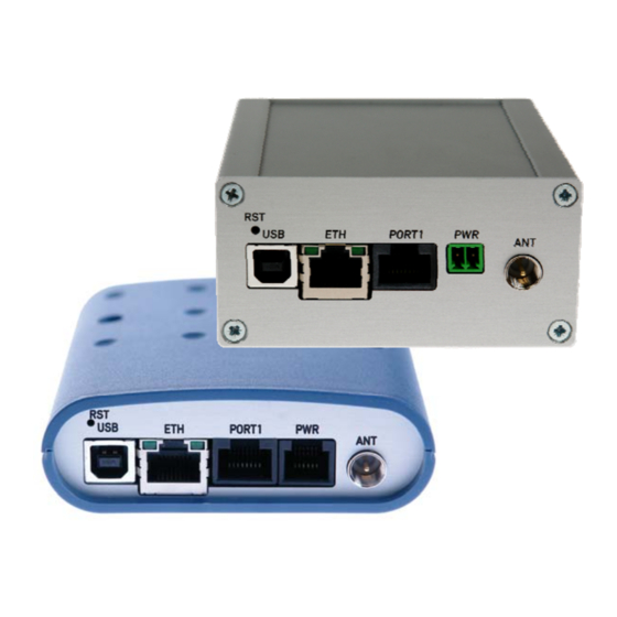
Page 11: User Interfaces (Connectors)
FME connector (ANT) – for connection of the antenna, • one USB-B connector (USB) – for connection of the router to the PC. Rear panel ER 75i and ER 75i DUO Front panel ER 75i Front panel ER 75i DUO... - Page 12 DESCRIPTION Rear panel ER 75i SL Front panel ER 75i SL LUCOM GmbH * Ansbacher Str. 2a * 90513 Zirndorf * Tel. 09127/59 460-10 * Fax. 09127/59 460-20 * www.lucom.de...
-
Page 13: Connection Of The Pwr Supply Connector
DESCRIPTION 2.8.1. Connection of the PWR Supply Connector • Panel socket RJ12. Signal Description number mark Positive pole of DC supply voltage (+10 to +30 VDC) Signal not connected Signal not connected Positive pole of DC supply voltage (+10 to +30 VDC) Negative pole of DC supply voltage Negative pole of DC supply voltage Circuit example:... -
Page 14: Connection Of The Eth Connector
DESCRIPTION 2.8.2. Connection of the ETH Connector Panel socket RJ45. Signal Data flow Description number mark direction TXD+ Transmit Data – positive pole Input/Output TXD- Transmit Data – negative pole Input/Output RXD+ Receive Data – positive pole Input/Output EPWR+ DC supply voltage from the switch – positive pole EPWR+ DC supply voltage from the switch –... -
Page 15: Connection Of The Optional Connector Port1
DESCRIPTION 2.8.4. Connection of the optional connector PORT1 Panel socket RJ45. 2.8.4.1. Expansion port RS232 (RS232 – DCE – Data Communication Equipment) Signal Data flow Description name direction Request To Send Input Clear To Send Output Data Terminal Ready Input Data Set Ready –... -
Page 16: Expansion Port Rs485
DESCRIPTION The router connection to equipment with full-value RS232 interface: Cable KD-2 Router PORT1 2.8.4.2. Expansion port RS485 Signal Data flow Description name direction SGND Signal and power supply ground SGND Signal and power supply ground TxRx- RS485 B (-) Input/Output TxRx+ RS485 A (+) -
Page 17: Expansion Port Rs422
DESCRIPTION Circuit example of the equipment with a router with data length more than 10 m: At RS485 data cable more then 10m it is need to use overvoltage protection on the router side! 2.8.4.3. Expansion port RS422 Signal Data flow Description name direction... - Page 18 DESCRIPTION Circuit example of the equipment with a router with data length more than 10 m: At RS422 data cable more then 10m it is need to use overvoltage protection on the router side! LUCOM GmbH * Ansbacher Str. 2a * 90513 Zirndorf * Tel. 09127/59 460-10 * Fax. 09127/59 460-20 * www.lucom.de...
-
Page 19: Expansion Port Mbus
DESCRIPTION 2.8.4.4. Expansion port MBUS Signal Data flow Description name direction SGND Signal and power supply ground SGND Signal and power supply ground TxRx- MBUS B (-) Input/Output TxRx+ MBUS A (+) Input/Output TxRx- MBUS B (-) Input/Output TxRx+ MBUS A (+) Input/Output +12V EXT External power supply +12V EXT External power supply... -
Page 20: Expansion Port Cnt
DESCRIPTION 2.8.4.5. Expansion port CNT Signal mark Description Data flow direction number BIN1/CNT1 Binary input/counter input Input BIN2/CNT2 Binary input/counter input Input BIN3 Binary input Input BIN4 Binary input Input Signal ground OUT1 Binary output (open collector) Output Analogue input Input Analogue input Input... -
Page 21: Technical Specification Of Optional Port1
DESCRIPTION 2.9. Technical specification of optional PORT1 • Expansion port RS232 Expansion port RS232 Power supply Internal ..Environment Operating temperature -20 .. +55 C Storage temperature -20 .. +85 C Standards Emission EN 55022/B Immunity ETS 300 342 Safety EN 60950 RS232 specifications Max. - Page 22 DESCRIPTION Jumper J3 Jumper J3 Jumper J2 Jumper J2 The jumper circuitry for internal supply The jumper circuitry for external supply Jumper J6 Jumpery J4 a J5 The jumper circuitry for RS485 The jumper circuitry for RS422 • Expansion port MBUS Name of product Expansion port MBUS Power supply...
- Page 23 DESCRIPTION • Expansion port CNT Name of product Expansion port CNT Power supply Internal …. Sleep 100 µA (counter is functional) Operation 2 mA Environment Operating temperature -20 .. +55 C Storage temperature -20 .. +85 C Standards Emission EN 55022/B Immunity ETS 300 342 Safety...
-
Page 24: Modem Status Indication
Off ...... the network cable is not connected 2.11. Putting into operation Before putting the ER 75i, ER 75i DUO or ER 75i SL router into operation it is necessary to connect all components needed for the operation of your applications and the SIM card must be inserted (the modem is off). -
Page 25: Mechanical External Dimensions And Mounting Recommendations
DESCRIPTION 2.12. Mechanical external dimensions and mounting recommendations LUCOM GmbH * Ansbacher Str. 2a * 90513 Zirndorf * Tel. 09127/59 460-10 * Fax. 09127/59 460-20 * www.lucom.de... - Page 26 DESCRIPTION For the majority of applications with a built-in modem in a switch board it is possible to recognize two sorts of environments: • non public and industry environment of low voltage with high interference, • public environment of low voltage without high interference. For both of these environments it is possible to mount modems to a switch board, the following is no need to have examination immunity or issues in connection with EMC according to EN 60439-1 ed.2.
- Page 27 DESCRIPTION • sufficient space must be left before individual connectors for handling of cables, • for correct function of the modem we recommend to use in switch - board earth- bonding distribution frame for grounding of power supply of modem, data cables and antenna, •...
-
Page 28: Expansion Port Mounting
EXPANSION PORT MOUNTING 3. Expansion port mounting 3.1. Expansion port mounting for ER 75i and ER 75i DUO router Attention! Expansion port includes when the router is switched off. After unscrewing two screws (position 8) on the box bottom part (position 4) and removing box top part (position 3), connect the expansion port PORT1 (position 2) to connector J3 (see below) of the router B-ER-75i motherboard (position 1) from the TOP side. - Page 29 EXPANSION PORT MOUNTING Parts list and description Part Description Number EDGE router motherboard Expansion port PORT1 Box top part Box bottom part Rear head Front head Spacers for expansion port PORT1 mounting to motherboard Screw for box completion LUCOM GmbH * Ansbacher Str. 2a * 90513 Zirndorf * Tel. 09127/59 460-10 * Fax. 09127/59 460-20 * www.lucom.de...
-
Page 30: Expansion Port Mounting For Er 75I Sl Router
EXPANSION PORT MOUNTING 3.2. Expansion port mounting for ER 75i SL router Attention! Expansion port includes when the router is switched off. After unscrewing four screws (position 10) on the rear panel (position 5) and removing it is possible to take out the B-ER-75i motherboard (position 1). The expansion port PORT1 (position 2) is connected to connector J3 (see below) of the router B-ER-75i motherboard (position 1) from TOP side. - Page 31 EXPANSION PORT MOUNTING Parts list and description Part Description Number EDGE router motherboard Expansion port PORT1 Left box part Right box part Rear head Front head Bottom box part Top box part Spacers for expansion port PORT1 mounting to motherboard Screw for box completion LUCOM GmbH * Ansbacher Str.
-
Page 32: Configuration Setting Over Web Browser
CONFIGURATION 4. Configuration setting over web browser Attention! If the SIM card is not inserted in the router, then it is impossible to operate. The inserted SIM card must have activated GPRS. Insert the SIM card when the router is switched-off. - Page 33 CONFIGURATION By each of the interfaces are then shown the following information • HWaddr – hardware (unique) address of networks interface • inet – own IP address • P-t-P – IP address second ends connection • Bcast – broadcast address •...
-
Page 34: Dhcp Status
CONFIGURATION 4.2. DHCP Status Information about IP addresses, which was leased to the router by the DHCP server, is possible to find in menu in sum DHCP: • lease 192.168.1.2 (generally IP address) – assigned IP address • starts – information about time of assignation of IP address •... -
Page 35: Dyndns Status
CONFIGURATION 4.5. DynDNS status DynDNS up - dating entry result on server www.dyndns.org can be called up in option DynDNS item in the menu. 4.6. System Log In case of any problems with connection to GPRS it is possible to view the system log by pressing the System Log menu item. -
Page 36: Lan Configuration
CONFIGURATION 4.7. LAN Configuration To enter the network configuration, select the LAN menu item. In the first part of the window it is possible to define the network interface IP address (IP address), the network mask (Subnet Mask) and media type (Media Type), in the majority of cases set Auto- Negotiation. - Page 37 CONFIGURATION Example of the network interface with dynamic and static DHCP server: 192.168.1.2 192.168.1.3 192.168.1.4 GSM/GPRS 192.168.1.1 192.168.1.10 01-23-45-67-89-ab 192.168.1.11 01-54-68-18-ba-7e LUCOM GmbH * Ansbacher Str. 2a * 90513 Zirndorf * Tel. 09127/59 460-10 * Fax. 09127/59 460-20 * www.lucom.de...
-
Page 38: Vrrp Configuration
CONFIGURATION 4.8. VRRP Configuration To enter the VRRP configuration select the VRRP menu item. VRRP protocol (Virtual Router Redundancy Protocol) is a technique, by which it is possible to forward routing from main router to backup router in the case of the main router failure. If the Enable VRRP is checked, then it is possible to set the following parameters. -
Page 39: Gprs Configuration
IP address when it is establishing the connection. If the APN field is not filled in, then ER 75i automatically selects the APN by the IMSI code of the SIM card. If the PLMN (operator number format) is not in the list of APN, then default APN is “internet“. - Page 40 The choice Get DNS address from operator is given for easier configuration on client side. If this field is filled in, then the ER 75i tries to get an IP address of primary and secondary DNS server from the operator automatically.
- Page 41 CONFIGURATION The changes in settings will apply after pressing the Apply button. Annotation: • MTU (Maximum Transmission Unit) – it is the identifier of the maximum size of packet, which is possible to transfer in a given environment. • MRU (Maximum Receiving Unit) – it is the identifier of the maximum size of packet, which is possible to receive in a given environment.
-
Page 42: Firewall Configuration
CONFIGURATION 4.10. Firewall Configuration By the help of a firewall it is possible to set IP addresses from which are possible to remotely access the router. The choice Allow remote access only from specified hosts is given for easier configuration of hosts. In this firewall configuration it is possible to set up to four remote accesses by the help of Source, Source IP Address, Protocol and Target Port. -
Page 43: Nat Configuration
Default Server item it is possible to put the ER 75i router into the mode in which all incoming data from GPRS will be routed to the computer with the defined IP address. If the Enable remote HTTP access field and port number is filled in, then configuration of the router over web interface is possible. - Page 44 CONFIGURATION In these configurations it is important to have marked choice of Send all remaining incoming packets it default server, IP address in this case is the address of the device behind the router. Connected equipment behind the router must have set Default Gateway on the router.
-
Page 45: Openvpn Tunnel Configuration
In this configuration equipment wired behind the ER 75i defines the address Server IP Address. The ER 75i replies, while PING on address of SIM card. Access on web interface of the equipment behind the ER 75i is possible by the help of Port Forwarding, when behind IP address of SIM is indicating public port of equipment on which we want to come up. - Page 46 CONFIGURATION renegotiate period (reauthorization) of the OpenVPN tunnel. This parameter is possible to set only at username/password authentication or at X.509 certificate using. By parameter Max Fragment Size it is possible to define maximum sending packet size. Sending data is possible compress by lossless LZO compressions by parameter Compression, compression has to be on both tunnel ends.
- Page 47 CONFIGURATION Example of the OpenVPN tunnel configuration: 192.168.1.2 192.168.2.2 ppp0 10.0.0.2 192.168.2.0 tun 0 19.16.2.0 ppp0 10.0.0.1 192.168.1.0 tun0 19.16.1.0 192.168.1.3 OpenVPN tunnel 192.168.2.3 192.168.1.4 192.168.2.4 Default Gateway 192.168.2.1 Default Gateway 192.168.1.1 OpenVPN tunnel configuration: Protocol UDP Port 1194 1194 Remote IP Address: 10.0.0.2 10.0.0.1...
-
Page 48: Ipsec Tunnel Configuration
CONFIGURATION 4.13. IPsec Tunnel Configuration IPsec tunnel configuration can be called up by option IPsec item in the menu. IPsec tunnel allows protected connection of two networks LAN to the one which looks like one homogenous. In the IPsec Tunnels Configuration window are four rows, each row for one configured IPSec tunnel. - Page 49 CONFIGURATION LUCOM GmbH * Ansbacher Str. 2a * 90513 Zirndorf * Tel. 09127/59 460-10 * Fax. 09127/59 460-20 * www.lucom.de...
-
Page 50: Gre Tunnel Configuration
CONFIGURATION Example of the IPSec Tunnel configuration: 192.168.1.2 192.168.2.2 ppp0 10.0.0.2 192.168.2.0 ppp0 10.0.0.1 192.168.1.0 192.168.1.3 IPSec tunnel 192.168.2.3 192.168.1.4 192.168.2.4 Default Gateway 192.168.1.1 Default Gateway 192.168.2.1 IPsec tunnel configuration: Remote IP Address: 10.0.0.2 10.0.0.1 Remote Subnet: 192.168.2.0 192.168.1.0 Remote Subnet Mask: 255.255.255.0 255.255.255.0 Local Subnet:... -
Page 51: L2Tp Tunnel Configuration
CONFIGURATION Address), internal IP address of the remote side of the tunnel (Remote Internal IP Address), address of the network behind the remote side of the tunnel (Remote Subnet) and the mask of the network behind the remote side of the tunnel (Remote Subnet Mask). The GRE tunnel is used for connection of two networks to one that appears as one homogenous. - Page 52 CONFIGURATION In the window it is possible to define L2TP tunnel mode (Mode) on the router side, in case of client IP address of server (Server IP Address), start IP address in range, which is offered by server to clients (Client Start IP Address), end IP address in range, which is offered by server to clients (Client End IP Address), IP address of the local side of the tunnel (Local IP Address), IP address of the remote side of the tunnel (Remote IP Address), address of the network behind the remote side of the tunnel (Remote Subnet), the mask...
-
Page 53: Dyndns Client Configuration
(Hostname), user name (Username) and password (Password). The changes in settings will apply after pressing the Apply button. Example of the DynDNS client configuration with domain conel.dyndns.org, username conel and password conel: If DNS servers are not assigned by the operator, then it is possible to configure it by inserting of script into start up window: echo “nameserver xxx.xxx.xxx.xxx“... -
Page 54: Ntp Client Configuration
CONFIGURATION 4.17. NTP Client Configuration NTP client Configuration can be called up by option NTP item in the menu. In the window can be defined the address prime (Primary NTP server Address) and secondary NTP server (Secondary NTP server Address), by the help of which the router, after first Example of NTP interface to the GPRS from make power supply, will adjust the inner clock. -
Page 55: Snmp Configuration
CONFIGURATION 4.18. SNMP Configuration To enter the SNMP Configuration it is possible with SNMP agent ver.1 configuration which sends information about the router, eventually about the status of the expansion port CNT or M-BUS. The Community item defines the password for access to the SNMP agent. Item Contact identifies a person who manages the router together with information how to contact this person, item Name is the designation of the router and item Location describes the physical placing of the router. -
Page 56: Sms Configuration
Example of the MIB browser: It is important to set the IP address of the SNMP agent (ER 75i) in field Remote SNMP agent. After enter the IP address is in a MIB tree part is possible show object identifier. - Page 57 Level – level signal After PPP connect, at introduction of the telephone number comes SMS in the form: ER 75i (Unit ID) has established PPP connection. IP address xxx.xxx.xxx.xxx After PPP disconnect, at introduction of the telephone number comes SMS in the form:...
- Page 58 CONFIGURATION IP address xxx.xxx.xxx.xxx ER 75i (Unit ID) has lost PPP connection. Configuration of sending this SMS is following: LUCOM GmbH * Ansbacher Str. 2a * 90513 Zirndorf * Tel. 09127/59 460-10 * Fax. 09127/59 460-20 * www.lucom.de...
- Page 59 CONFIGURATION Example of the router onfiguration for SMS sending via serial interface: The SMS is possible to do for example in HyperTerminal program. After establishing connection with the router via serial interface or Ethernet, it is possible to do with SMS by the help of the next AT commands (more about AT commands see reference [1]): AT commands Description...
- Page 60 CONFIGURATION It is possible to find the new SMS by the help of command AT+CMGL=ALL. This command reproaches all SMS messages. AT+CMGL=ALL Enter +CMGL: <index>, <status>,<sender number>, ,<date>,<time> SMS text. +CMGL: 1,“REC UNREAD“,“+420721123456“, ,“08/02/02, 10:33:26+04“ Hello World! where <index> is ordinal number of the SMS, <status>...
-
Page 61: Expansion Port Configuration
CONFIGURATION 4.20. Expansion port Configuration The expansion port configuration can be called up by airbrush option External Port in menu. Inside the window can be defined Baudrate, number of Data bits, Parity, number of Stop bits, Protocol and Mode. Split timeout is for messages. In mode TCP server it is necessary to enter the TCP port, on which the router will listen to incoming requests about TCP connection. -
Page 62: Start-Up Script
CONFIGURATION ppp0 10.0.0.2 RS232 ppp0 10.0.0.1 RS232 ER-75i settings ER-75i settings Mode: TCP server Mode: TCP client Server Address: - Server Address: 10.0.0.2 TCP Port: 2000 TCP Port: 2000 4.21. Start-up script In the window Startup Script it is possible to create own scripts which will be executed after all initial scripts. -
Page 63: Change Password
CONFIGURATION automatically and it isn’t needed to enter this. By parameter Unit ID enabled it defines the concrete configuration name which will be download to the router. When using parameter Unit ID, hardware MAC address in configuration name will not be used. Automatic configuration update starts 5 minutes after turning on the router and then every 24 hours or it is possible to set the time of automatic configuration in parameter Update Hour. -
Page 64: Set Sms Service Center Address
CONFIGURATION 4.25. Set SMS service center address In some cases it is need to set phone number of the SMS service centre because of SMS sending. This parameter can not be set when the SIM card has set phone number of the SMS service centre. -
Page 65: Restore Configuration
CONFIGURATION 4.29. Restore Configuration In case it is needed to restore the router configuration, it is possible in Restore Configuration menu item to check configuration by help Browse button. 4.30. Update firmware To view the information about the firmware version and instructions for its update select the Update Firmware menu item. -
Page 66: Default Settings
CONFIGURATION 4.32. Default settings 4.32.1. LAN Configuration 4.32.2. VRRP Configuration 4.32.3. Firewall Configuration LUCOM GmbH * Ansbacher Str. 2a * 90513 Zirndorf * Tel. 09127/59 460-10 * Fax. 09127/59 460-20 * www.lucom.de... -
Page 67: Gprs Configuration
CONFIGURATION 4.32.4. GPRS Configuration 4.32.5. NAT Configuration LUCOM GmbH * Ansbacher Str. 2a * 90513 Zirndorf * Tel. 09127/59 460-10 * Fax. 09127/59 460-20 * www.lucom.de... -
Page 68: Openvpn Tunnel Configuration
CONFIGURATION 4.32.6. OpenVPN Tunnel Configuration LUCOM GmbH * Ansbacher Str. 2a * 90513 Zirndorf * Tel. 09127/59 460-10 * Fax. 09127/59 460-20 * www.lucom.de... -
Page 69: Ipsec Tunnel Configuration
CONFIGURATION 4.32.7. IPsec Tunnel Configuration LUCOM GmbH * Ansbacher Str. 2a * 90513 Zirndorf * Tel. 09127/59 460-10 * Fax. 09127/59 460-20 * www.lucom.de... -
Page 70: Gre Tunnel Configuration
CONFIGURATION 4.32.8. GRE Tunnel Configuration 4.32.9. L2TP Configuration 4.32.10. DynDNS Configuration 4.32.11. NTP Configuration LUCOM GmbH * Ansbacher Str. 2a * 90513 Zirndorf * Tel. 09127/59 460-10 * Fax. 09127/59 460-20 * www.lucom.de... -
Page 71: Snmp Configuration
CONFIGURATION 4.32.12. SNMP Configuration 4.32.13. SMS Configuration LUCOM GmbH * Ansbacher Str. 2a * 90513 Zirndorf * Tel. 09127/59 460-10 * Fax. 09127/59 460-20 * www.lucom.de... -
Page 72: External Port Configuration
CONFIGURATION 4.32.14. External Port Configuration 4.32.15. Startup Script 4.32.16. Automatic Update LUCOM GmbH * Ansbacher Str. 2a * 90513 Zirndorf * Tel. 09127/59 460-10 * Fax. 09127/59 460-20 * www.lucom.de... -
Page 73: Configuration Setting Over Telnet
CONFIGURATION Configuration setting over Telnet Attention! If the SIM card isn’t included in the router, it is impossible for the router to operate. The Included SIM card must be activated for GPRS transmissions. Insert the SIM card when the router is switched off. Monitoring of status, configuration and administration of the router can be performed by means of the Telnet interface. -
Page 74: Driver Installation
DRIVERS Driver installation Connect the USB cable to the router and to the PC. Windows detects router as a new USB modem, starts the Add Hardware wizard and requests the driver for "MC75i" or „Siemens AG WM USB Modem“. Follow the instructions of the wizard and enter the path to the "usbmodem.inf"... - Page 75 DRIVERS You will find the installed modem in the Phone and modem options control panel (Start | Settings | Control Panel | Phone and Modem Options | Modems). You can change the assigned COM port in the Device Manager. Select “Siemens AG WM USB Modem”...
-
Page 76: Control By At Commands
AT COMMANDS, PROBLEMS, REFERENCE AND FAQ 7. Control by AT commands The router is controlled and programmed by AT commands. Structure of the AT command match used module MC75i. AT commands are possible to find on website www.siemens.com/wm. 8. Possible problems Some network cards are able to be set in situation, when it is not possible to connect the router. -
Page 77: Customer's Care
During cleaning of the modem do not use aggressive chemicals, solvents and abrasive cleaners! Conel Company hereby declares that the modem narrated in this user’s guide fits all basic demands of directive 1999/5/EC (R&TTE). Declaration about consistency was issued and is possible get it at producer. -
Page 78: Product Disposal Information
DISPOSAL INFORMATIONS 12. Product disposal information The WEEE (Waste Electrical and Electronic Equipment: 2002/96/EC) directive has been introduced to ensure that electrical/electronic products are recycled using the best available recovery techniques to minimise the impact on the environment. This product contains high quality materials and components which can be recycled. -
Page 79: Guarantee Claim Guidelines
GUARANTEE CLAIM GUIDELINES 13. Guarantee Claim Guidelines Dear customer, The product that you have purchased was tested by the manufacturer and, before it was sold, the product’s functions were checked once more by our company’s technician. However if, in spite of the above-mentioned measures, a breakdown of this product occurs during the guarantee period, which makes proper utilization of the product impossible, we ask you to observe the Guarantee Claim Guidelines when asserting a guarantee claim. - Page 80 GUARANTEE CLAIM GUIDELINES hereupon onto the seller, and the ownership of the new product, onto the buyer. A new guarantee period starts running from the date of acceptance of the new product. In the event that the seller, upon agreement with the customer, has settled the guarantee claim by exchanging the object of the guarantee claim for a faultless product, the new guarantee of the product shall expire as follows: 1.
- Page 81 GUARANTEE CLAIM GUIDELINES Other guarantee claim conditions The fact that the object of the guarantee claim does not correspond to parameters that have been set for other similar types of products can not be considered to be a defect. For the assessment whether a defect has occurred, the product parameters included in the technical documentation of the product are decisive.
-
Page 82: Guarantee Certificate
GUARANTEE CERTIFICATE 14. Guarantee certificate Type of the device Serial number Guarantee period (in months) Seller Date of sale Stamp of the seller LUCOM GmbH * Ansbacher Str. 2a * 90513 Zirndorf * Tel. 09127/59 460-10 * Fax. 09127/59 460-20 * www.lucom.de... - Page 83 GUARANTEE CERTIFICATE Date of reception of the guarantee claim by the seller Number of the guarantee claim report Date of reception of the device into the repair shop Date of completion of the repair by the repair shop Number of the receipt form of the repair shop Guarantee repair...
Need help?
Do you have a question about the ER 75i and is the answer not in the manual?
Questions and answers