
Subscribe to Our Youtube Channel
Related Manuals for Planet GT-902


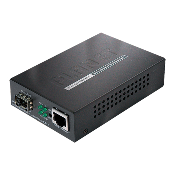
Summary of Contents for Planet GT-902
- Page 1 User's Manual GT-902 GT-902S GT-905A GT-906A15 / GT-906B15 GT-906A60 / GT-906B60 GT-906A80 / GT-906B80 10/100/1000Base-T to 1000Base-SX / LX Managed Media Converter...
-
Page 2: Fcc Warning
PLANET has made every effort to ensure that this User's Manual is accurate; PLANET disclaims liability for any inaccuracies or omissions that may have occurred. - Page 3 WEEE as unsorted municipal waste and have to collect such WEEE separately. Revision PLANET Managed Gigabit Ethernet Media Converter User's Manual FOR MODELS: GT-902 / GT-902S / GT-905A / GT-906A15 / GT-906B15 / GT-906A60 / GT-906B60 / GT-906A80 / GT-906B80 REVISION: 1.1 (June.2010)
-
Page 4: Table Of Contents
3.2 M ............................. 12 ANAGEMENT ETHODS 3.2.1 Web Management............................. 13 3.2.2 SNMP Management............................13 3.2.3 PLANET Smart Discovery Utility ........................14 3.2.4 Login the Managed Media Converter ........................ 15 4. WEB MANAGEMENT..............................16 4.1 M ................................16 4.2 S ..................................17 YSTEM 4.2.1 System Information ............................ - Page 5 4.7.1 Local TS-1000 OAM Setup ..........................44 4.7.2 Remote TS-1000 OAM Setup ........................... 45 4.7.3 TS-1000 Loop Back Test ..........................47 4.7.4 802.3ah Setup..............................49 4.7.5 802.3ah Loop Back Test ........................... 50 4.8 S .................................. 52 ECURITY 4.9 L ..................................53 OGOUT 5.
-
Page 6: Introduction
1. INTRODUCTION 1.1 Package Contents Check the contents of your package for following parts: Managed Gigabit Ethernet Media Converter x1 ● CD-ROM User's Manual x1 ● Quick Installation Guide x1 ● External DC 5V / 2A Power Adapter x 1 ●... -
Page 7: About The Managed Media Converter
This Managed Media Converter can be used as a stand-alone unit or as a slide-in module to the PLANET Media Converter Chassis (MC-700, MC-1500 and MC-1500R / MC-1500R48). The Managed Media Converter equipped with remote Web / SNMP interface. With its built-in Web-based management, the Managed Media Converter offers an easy-to-use, platform-independent management and configuration facility and can be programmed for advanced management functions. -
Page 8: Product Features
1000Base-LX WDM interface for up to 80km (single-mode fiber 9μm/125μm) on GT-906A80/B80 1000Base-T: 2-pair Cat. 5/5e/6 UTP cable, up to 100 meters Compacts size for working with PLANET MC family Media Chassis ( MC-700/1500/1500R / 1500R48) Wall-mountable hardware designed Built-in IP-Base Web interface for remote management... -
Page 9: Product Specification
TS-1000 OAM / IEEE 802.3ah OAM / Loop Back Test 16 TCP / UDP Filter groups Password setting, IP setting and devices description setting through Planet Smart discovery utility Firmware upgrade via remote Web interface External DC 5V 2A power supply... - Page 10 94 x 70 x 26mm (W x D x H) Dimensions Operator Environment Operating temperature: 0 to 50 Degree C; Humidity: 5~90% non-condensing Storage Environment storage temperature: -10 to 70 Degree C; Humidity: 5~90% non-condensing FCC Class A, CE Class A Emissions Model GT-906A60...
-
Page 11: Hardware Description
1000Base-LX WDM ports and one Auto-Sensing 10/100/1000Mbps Ethernet RJ-45 Port. Figure 2-1 & 2-2 & 2-3 shows a front panel of Managed Media Converter. Figure 2-1 PLANET GT-902 / GT-902S Front Panel Figure 2-2 PLANET GT-905A Front Panel Figure 2-3 PLANET GT-906A/B Front Panel... -
Page 12: Led Indicators
2.1.1 LED Indicators Color Description Lit: When +5VDC power detected. Green Lit: To indicate the link through that fiber port is successfully established. Fiber LNK/ACT Green Blink: Indicate that the Fiber port is actively sending or receiving data over that port. Lit: To indicate the link through that port is successfully established. -
Page 13: Install The Converter
2.2 Install the Converter This section describes how to install your Managed Media Converter and make connections to the Managed Media Converter. Please read the following topics and perform the procedures in the order being presented. The hardware installation of Managed Media Converter do not need software configuration. To install your Managed Media Converter on a desktop or shelf, simply complete the following steps. - Page 14 Step 3: Connect the fiber cable. Attach the duplex LC connector on the network cable into the SFP transceiver. It recommends using PLANET MGB series 1000Base-SX / LX / LX WDM SFP on the GT-905A. If you insert a SFP transceiver that is not supported, the GT-905A will not recognize it.
-
Page 15: Chassis Installation And Rack Mounting
2.2.2 Chassis Installation and Rack Mounting To install the Managed Media Converter in a 10-inch or 19-inch with standard rack, follow the instructions described below. Step 1: Place your Managed Media Converter on a hard flat surface, with the front panel positioned towards your front side. - Page 16 Figure 2-6 Mounting the Chassis in a Rack -11-...
-
Page 17: Media Converter Management
3. MEDIA CONVERTER MANAGEMENT This chapter describes how to manage the Managed Media Converter. Topics include: - Overview - Management methods - Assigning an IP address to the Managed Media Converter - Logging on to the Managed Media Converter 3.1 Overview This chapter gives an overview of Managed Media Converter management. -
Page 18: Web Management
3.2.1 Web Management The PLANET Managed Media Converter provides a built-in browser interface. You can manage the Managed Media Converter remotely by having a remote host with Web browser, such as Microsoft Internet Explorer, Netscape Navigator or Mozilla Firefox. The following shows how to startup the Web Management of the Managed Media Converter, please note the Managed Media Converter is configured through an Ethernet connection, make sure the manager PC must be set on the same IP subnet address, for example, the default IP address of the Managed Media Converter is 192.168.0.100 (the... -
Page 19: Planet Smart Discovery Utility
3.2.3 PLANET Smart Discovery Utility For easily list the Managed Media Converter in your Ethernet environment, the Planet Smart Discovery Utility from user’s manual CD-ROM is an ideal solution. The following install instructions guiding you for run the Planet Smart Discovery Utility. -
Page 20: Login The Managed Media Converter
6. Press “Connect to Device” button then the Web login screen appears in Figure 3-3. 7. Press “Exit” button to shutdown the planet Smart Discovery Utility. 3.2.4 Login the Managed Media Converter Before you start configure the Managed Media Converter, please note the Managed Media Converter is configured through an Ethernet connection, make sure the manager PC must be set on same the IP subnet address. -
Page 21: Web Management
4. WEB MANAGEMENT The GT-90X Managed Media Converter provide Web interface for management function configuration and make the Managed Media Converter operate more effectively - They can be configured through the Web Browser. A network administrator can manage and monitor the Managed Media Converter from the local LAN. This section indicates how to configure the Managed Media Converter to enable its management function. -
Page 22: System
4.2 System 4.2.1 System Information The System Information Web page provides information for the current device. System Information Web page helps network administrator to identify the firmware versions, IP Subnet Address and etc. The screen in Figure 4-2 appears and Table 4-1 describes the System Information object of Managed Media Converter. -
Page 23: Ip Configuration
4.2.2 IP Configuration The IP Configuration includes the DHCP Client, IP Address, Subnet Mask, Gateway and Description. The screen in Figure appears and Table 4-2 describes the IP Configuration object of Managed Media Converter. Figure 4-3 IP Configuration Web page screen The IP Configuration Web page screen includes the following configurable data: Allow disable or enable the DHCP Client function of the Managed Media Converter, the factory DHCP Client... -
Page 24: Password Setting
4.2.3 Password Setting This function provides administrator to secure Web login. The screen in Figure 4-4 & 4-5 appears and Table 4-3 describes the Password Setting object of Managed Media Converter. Figure 4-4 Password Setting Web page screen Figure 4-5 Password Setting Successful Web page screen -19-... -
Page 25: Firmware Upgrade
The Password Setting Web page includes the following configurable data: Displays the user name (admin). Login Name Enter the old password is required before entering the new password. Old Password Specifies the new password. The password is not displayed. As it entered an “ ” New Password corresponding to each character is displayed in the field. - Page 26 Press “Browser” button to find the firmware location administrator PC, The screen in Figure 4-7 appears Figure 4-7 Firmware Upgrade Web page screen After find the firmware location from administrator PC, press “Upgrade” button to start the firmware upgrade process. The screen in Figure 4-8 &...
- Page 27 Figure 4-9 Firmware Upgrade Web page screen When firmware upgrade process is completed then the following screen appears, please click “here” to re-login the Managed Media Converter with latest firmware and the screen in Figure 4-10 & 4-11 appears. Figure 4-10 Firmware Upgrade Web page screen -22-...
- Page 28 Figure 4-11 Login Web page screen -23-...
-
Page 29: Snmp Management
4.2.5 SNMP Management This function provides SNMP Management and SNMP Trap Receiver Configuration function of the Managed Media Converter and the screen in Figure 4-12 & 4-13 appears and Table 4-4 & 4-5 describes the SNMP Management and SNMP Trap Receiver object of Managed Media Converter. Figure 4-12 SNMP Management Web page screen The SNMP Management Web page includes the following configurable data: Allow disable or enable the SNMP Agent function, the default mode is “Disable”. - Page 30 Figure 4-13 SNMP Trap Receiver Configuration Web page screen The SNMP Trap Receiver Configuration Web page includes the following configurable data: Allow disable or enable the SNMP Trap function, the default mode is “Disable”. SNMP Trap Allow input the IP address of SNMP Trap Destination. SNMP Trap Destination When Managed Media Converter executes Cold Start operation, the Cold Start...
-
Page 31: Factory Default
4.2.6 Factory Default This function provides Factory Default function of the Managed Media Converter and the screen in Figure 4-14 & 4-15 & 4-16 appears. Figure 4-14 Factory Default Web page screen Figure 4-15 Factory Default Web page screen -26-... -
Page 32: System Reboot
Figure 4-16 Login Web page screen 4.2.7 System Reboot This function provides System Reboot function of the Managed Media Converter and the screen in Figure 4-17 & 4-18 & 4-19 appears. Figure 4-17 System Reboot Web page screen -27-... - Page 33 Figure 4-18 System Reboot Web page screen Figure 4-19 Login Web page screen -28-...
-
Page 34: Port Management
4.3 Port Management 4.3.1 Port Configuration This function allows displaying TP / Fiber port status. The Link Status in the screen displays the current connection speed and duplex mode; else this function will show red when the TP / Fiber port is disconnected. Press the “Refresh” “Down”... - Page 35 Flow Control Allow Disable or Enable Flow Control of TP or Fiber port. • Enable – IEEE 802.3x Flow Control is enabled on Full-Duplex mode or Backpressure is enabled on Half-Duplex mode • Disable – No Flow Control or backpressure function on no matter Full-Duplex or Half-Duplex mode Default mode: Disable The value of inbound traffic limitation in kilobit-per-second (kbps).
- Page 36 Figure 4-21 Port Configuration-Ingress Rate Limit Web Page screen Figure 4-22 Port Configuration-Egress Shaping Web Page screen -31-...
-
Page 37: Port Status
4.3.2 Port Status This function allows displaying TP / Fiber port detail status, such as Link Status, Duplex Mode, Flow control, Speed and Auto negotiation. Press the “Refresh” button to renew the screen, the screen in Figure 4-23 appears and Table 4-7 describes the Port Status object of Managed Media Converter. -
Page 38: Port Statistics
4.3.3 Port Statistics This function allows displaying TP / Fiber port detail Statistics, press the “Clear” button to clear current counter information. Press the “Refresh” button to renew the screen, the screen in Figure 4-24 & 4-25 appears. Figure 4-24 Port Statistics Web Page screen Figure 4-25 Port Statistics Web Page screen -33-... -
Page 39: Converter Configuration
4.4 Converter Configuration This function provides useful setting for the Managed Media Converter, such as Maximum Packet length, Loop detection, storm control and etc. The screen in Figure 4-26 appears and Table 4-8 describes the Converter Configuration object of Managed Media Converter. Figure 4-26 Converter Configuration Web Page screen The Converter Configuration Web page includes the following configurable data: Maximum Packet Length... -
Page 40: Vlan
Provide storm Filter Timer setting and the available options are: Storm Filter Timer 800ms 400ms 200ms 100ms Default mode is 800ms. Apply button Press this button for save current configuration of Managed Media Converter. Table 4-8 Descriptions of the Converter Configuration Web Page Screen Objects 4.5 VLAN A Virtual LAN (VLAN) is a logical network grouping that limits the broadcast domain. - Page 41 802.1Q Tag User Priority VLAN ID (VID) 3 bits 1 bits 12 bits TPID (Tag Protocol Identifier) TCI (Tag Control Information) 2 bytes 2 bytes Destination Source Ethernet Preamble Data VLAN TAG Address Address Type 6 bytes 6 bytes 4 bytes 2 bytes 46-1517 bytes 4 bytes...
-
Page 42: Vlan Group
Default VLANs The Managed Media Converter initially configures one VLAN, VID = 1, called "default." The factory default setting assigns all ports on the Managed Media Converter to the "default". As new VLAN are configured in Port-based mode, their respective member ports are removed from the "default." 4.5.1 VLAN Group This function allows disable or enable the IEEE 802.1Q VLAN operation mode. - Page 43 Figure 4-28 VLAN Group Web Page screen The VLAN Group Web page includes the following configurable data: VLAN Mode Provide Disable or enable the IEEE 802.1Q VLAN operation mode. Default mode is Disable. Management VLAN Group Provide define the Management VLAN group. Default mode is VLAN1. Indicate the VLAN Group from 1 to 16.
-
Page 44: Vlan Per Port Setting
4.5.2 VLAN Per Port Setting This function provides IEEE 802.1Q VLAN per port setting for TP and Fiber port of Managed Media Converter. Press the “Apply” button to save the current configuration of Managed Media Converter. The screen in Figure 4-29 appears and Table 4-10 describes the VLAN Per Port Setting object of Managed Media Converter. -
Page 45: Q-In-Q Vlan Setting
4.5.3 Q-in-Q VLAN Setting When enable Q-in-Q function, Managed Media Converter can insert or remove 4-bytes Q-in-Q tag in the received 802.3 frames after SA. User can define Q-in-Q tag value freely. And in default condition, Q-in-Q tag format is same as VLAN tag. In normal application, enable two port’s Q-in-Q function. -
Page 46: Quality Of Service
4.6 Quality of Service Quality of Service (QoS) is an advanced traffic prioritization feature that allows you to establish control over network traffic. QoS enables you to assign various grades of network service to different types of traffic, such as multi-media, video, protocol-specific, time critical, and file-backup traffic. - Page 47 The Quality of Service Web page includes the following configurable data: Qos Mode Provide 4 different QoS mode for operation, the available options are: Disable 802.1p Tag Priority The 802.1p Tag Priority field as show in Figure 4-32. IP Address Priority The IP Address Priority field as show in Figure 4-33.
- Page 48 Figure 4-33 IP Address Priority Web Page screen Figure 4-34 IP DSCP Priority Web Page screen -43-...
-
Page 49: Oam Setup
4.7 OAM Setup 4.7.1 Local TS-1000 OAM Setup This function provides Local TS-1000 OAM Setup of Managed Media Converter. Press the “Apply” button to save the current configuration of Managed Media Converter. The screen in Figure 4-35 appears and Table 4-13 describes the Local TS-1000 OAM Setup object of Managed Media Converter. -
Page 50: Remote Ts-1000 Oam Setup
4.7.2 Remote TS-1000 OAM Setup The Remote TS-1000 OAM Setup is an advanced remote device monitor feature that allows you to Remote monitor and automatic notify status indication. Remote monitor 1. User instructs center Media Converter to issue a status notification request frame defined in TS-1000 to get status of terminal Media Converter. - Page 51 Figure 4-37 GT-90x Remote TS-1000 OAM Setup Web Page screen Please use the PLANET GT-80x and GT-90x as the Remote device. Notice: -46-...
-
Page 52: Ts-1000 Loop Back Test
4.7.3 TS-1000 Loop Back Test The TS-1000 Loop Back Test allows manual run this loop back test to check the interconnection between two Media Converter devices. To assure the Remote TS-1000 OAM function can work correctly. In-band and out-band Loop back 1. - Page 53 Display the TS-1000 Loop Back Test Result. Fail or Pass. Result counter Display the value of Counter Result. Table 4-14 Descriptions of the TS-1000 Loop Back Test Web Page Screen Objects Please use the PLANET GT-80x and GT-90x as the Remote device. Notice: -48-...
-
Page 54: 802.3Ah Setup
4.7.4 802.3ah Setup When enable 802.3ah OAM function, all 802.3ah OAMPDU packets will trap to embedded CPU. Software will implement auto discovery procedure. With hardware support, software controls the 802.3ah remote loop back procedure. Hardware can also detect dying gasp even and interrupt CPU to send dying gasp even notification OAMPDU. -
Page 55: 802.3Ah Loop Back Test
1. The 802.3ah function must work with manageable device that supports 802.3ah function. Notice: 2. Please use the PLANET GT-90x as the Remote device. 4.7.5 802.3ah Loop Back Test The 802.3ah Loop Back Test allows manual run this loop back test to check the interconnection between two Media Converter devices. - Page 56 Display the 802.3ah Loop Back Test Result. Fail or Pass. Table 4-16 Descriptions of the 802.3ah Loop Back Test Web Page Screen Objects 1. The 802.3ah function must work with manageable device that supports 802.3ah function. Notice: 2. Please use the PLANET GT-90x as the Remote device. -51-...
-
Page 57: Security
4.8 Security This function provides TCP / UDP Filter setting of Managed Media Converter. Press the “Apply” button to save the current configuration of Managed Media Converter. The screen in Figure 4-41 appears and Table 4-17 describes the TCP / UDP Filter setting object of Managed Media Converter. Figure 4-41 Security setting Web Page screen The Quality of Service Web page includes the following configurable data: Group ID... -
Page 58: Logout
4.9 Logout This function provides Logout function of Managed Media Converter, when the “Are you sure to logout” pop window appears; press the “OK” button to logout Web page of Managed Media Converter. The screen in Figure 4-42 & 4-43 appears. -
Page 59: Troubleshooting
5. TROUBLESHOOTING This chapter contains information to help you solve problems. If the media converter is not functioning properly, make sure the media converter was set up according to instructions in this manual. The Link LED is not lit Solution: Check the cable connection and remove duplex mode of the Managed Media Converter. -
Page 60: Appendix A Networking Connection
APPENDIX A NETWORKING CONNECTION A.1 Device‘s RJ-45 Pin Assignments ■ 1000Mbps, 1000Base T RJ-45 Connector pin assignment Contact MDI-X BI_DA+ BI_DB+ BI_DA- BI_DB- BI_DB+ BI_DA+ BI_DC+ BI_DD+ BI_DC- BI_DD- BI_DB- BI_DA- BI_DD+ BI_DC+ BI_DD- BI_DC- 10/100Mbps, 10/100Base-TX RJ-45 Connector pin assignment MDI-X Contact Media Dependant... -
Page 61: Fiber Optical Cable Connection Parameter
There are 8 wires on a standard UTP/STP cable and each wire is color-coded. The following shows the pin allocation and color of straight cable and crossover cable connection: Figure A-1: Straight-Through and Crossover Cable Please make sure your connected cables are with same pin assignment and color as above picture before deploying the cables into your network. -
Page 62: Power Information
The power jack of Managed Media Converter is with 2.5mm in the central post and required +5VDC power input. It will conform to the bundled AC-DC adapter and Planet’s Media Chassis. Should you have the problem to make the power connection, please contact your local sales representative. -
Page 63: Ec Declaration Of Conformity
15,60 for different distance * Produced by: Manufacturer‘s Name : Planet Technology Corp. Manufacturer‘s Address : 11F, No. 96, Min Chuan Road, Hsin Tien, Taipei, Taiwan, R.O.C. is herewith confirmed to comply with the requirements set out in the Council Directive on the Approximation of the Laws of the Member States relating to Electromagnetic Compatibility Directive on (89/336/EEC).
Need help?
Do you have a question about the GT-902 and is the answer not in the manual?
Questions and answers