Beam RST310 Installation And User Manual
9505a intellidock docking station
Hide thumbs
Also See for RST310:
- Installation and user manual (34 pages) ,
- Installation and user manual (35 pages) ,
- Installation and user manual (56 pages)

Related Manuals for Beam RST310


Summary of Contents for Beam RST310
-
Page 1: Docking Station
RST310 9505A IntelliDOCK Docking Station Installation and User Manual Beam Communications Pty Ltd... - Page 2 8 Anzed Court, Mulgrave, Victoria, 3170, AUSTRALIA Information furnished by Beam Communications Pty Ltd (Beam) is believed to be accurate and reliable. However, no responsibility is assumed by Beam for its use, or for any infringement of patents or other rights of third parties, which may result from its use. No license is granted by implication or otherwise under any patent or patent rights of Beam.
-
Page 3: Table Of Contents
WHAT IS THE RST310?............................10 RST310 O ............................11 VERVIEW The Front Panel ............................. 11 The Rear Panel .............................. 11 The RST310 Status Indicators ........................12 Display Status Indicators..........................12 PACKAGE CONTENTS............................14 RST310 : ........................14 PACKAGE CONTAINS ............................. 14... - Page 4 RST310 USER & INSTALLATION MANUAL RST310 SMS-POTS....................33 ONFIGURING THE DATA SETTINGS AUTO ANSWER ........................34 Data Terminal settings for auto-answering an incoming data call............34 REMOTE CONFIGURATION..........................35 INTELLIGENT HANDSET USE.......................... 37 ) ......................37 NTELLIGENT ANDSET OPTIONAL Connecting an Intelligent Handset......................38 Symbols on the Intelligent Handset versus the 9505A ................
-
Page 5: Safety Information
Note: Read the following information before installing and using the BEAM RST310. Your RST310 is a low power radio transmitter and receiver. When it is ON, it receives and sends out radio frequency (RF) signals. The design of your RST310 system complies with international safety standards. -
Page 6: Welcome
This Installation and Configuration manual contains all the information you need to install and configure the Beam RST310 and discover the advantages of Beam Communications and Iridium Network technology. The RST310 User and Installation Manual is for new and experienced users of wireless network systems. -
Page 7: Conventions In This Manual
RST310 USER & INSTALLATION MANUAL Conventions in this Manual Warnings, cautions and notes appear throughout this manual. They are represented by following conventions. Warning: This symbol and associated text indicate a warning note providing information to prevent personal injury or damage to equipment. -
Page 8: About Beam Communications
RST310 USER & INSTALLATION MANUAL About BEAM Communications Beam Communications, is an authorised manufacturer of Iridium Satellite products. Beam develops subscriber products that utilise the Iridium satellite network of Low Earth Orbit satellites, known as LEOs. The Iridium network is extensively used around the world by commercial enterprises and defence agencies. -
Page 9: Important Powering Information
RST310 USER & INSTALLATION MANUAL Important Powering Information Powering up the RST310A Terminal 1. Turn off power to the terminal. 2. Ensure that all the cables are connected to the 9505A handset as shown below External Antenna Power Audio / Mic... -
Page 10: What Is The Rst310
The RST310 provides a serial control interface and audio input and outputs by way of the transceiver’s control and connection interface. -
Page 11: Rst310 Overview
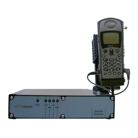
RST310 USER & INSTALLATION MANUAL RST310 Overview The Front Panel Figure 1 - The RST310 front panel Status LEDS Power Voicemail waiting* SMS waiting Call status Signal strength * Subject to network availability The Rear Panel Figure 2 - The RST310 rear... -
Page 12: The Rst310 Status Indicators
RST310 USER & INSTALLATION MANUAL The RST310 Status Indicators The status indicators are located on the front panel of the RST310. The LED lights on the front panel show the RST310 status. Note: The LED lights will blink in different combinations to indicate transmission such things as transmission status, signal strength and power. - Page 13 Iridium network at your location. This LED displays different colours to indicate the strength of the RF (Radio Frequency) signal and different on/off conditions to indicate the terminal status. Indictor colour Signal strength Flashing RST310 is registering with the network – please wait Green Strong Orange Acceptable...
-
Page 14: Package Contents
RST310 USER & INSTALLATION MANUAL Package Contents The RST310 package contains: 1 RST310 unit 1 universal plug-pack power adapter, 110-240V AC 1 9-pin-to-9-pin RS-232 cable (Male to Female) 1 user manual in hard copy Ram Mount Bracket 9505A handheld connector Cables... -
Page 15: Getting Started
A SIM Card (Subscriber Identity Module) is a small smart card that carries your identity for accessing the network and receiving calls. It functions as the digital memory of the RST310 and also stores your personal information, including received SMS messages. -
Page 16: Pin Details
RST310 USER & INSTALLATION MANUAL PIN Details The RST has a number of different PINs, each one to perform or limit certain functions. The table below identifies these PINS, their function and a place for you to note the setting for your unit. -
Page 17: Installing Rst310
RST310 USER & INSTALLATION MANUAL Installing RST310 This chapter explains how to install the RST310 and the Iridium fixed-mast antenna. Warning: Make sure the RST310 is switched off before you install the cables. If you do not, the RST310 may be damaged. -
Page 18: Mounting Methods
RST310 USER & INSTALLATION MANUAL Mounting methods The mounting brackets allow two mounting methods: drop-in (inside corner) mount and flush (outside corner) mount. Figure 3 - Mounting methods To install the RST310 unit There are two options for affixing the docking station to a fixed location. - Page 19 RST310 USER & INSTALLATION MANUAL 2. Secure the RST310 unit to the mounting brackets using supplied screws. 3. Carefully slot the RST310 between the two mounting brackets and secure with the retaining screws. 4. Mount the Ram-mount cradle for the 9505A in the desired location ensuring that there is sufficient cable length for the handset to connect to the main terminal.
- Page 20 RST310 USER & INSTALLATION MANUAL Option 2, Using the brackets supplied the Ram-mount handset holder can be firmly attached to the terminal as pictured below, follow the above instructions for mounting the terminal, however using the longer mounting screws supplied affix the additional ram- mount holding bracket to the side of the unit.
-
Page 21: Connecting The Power Cable
RST310 USER & INSTALLATION MANUAL Connecting the Power Cable 1. Make sure the AC power switch supplying the RST310 power pack is off. 2. Plug in the power cable into the power jack located on the rear panel of the RST310. -
Page 22: Connecting The Handsets
Messaging is not supported on the Iridium Network via a standard RJ11 connection. 2. Plug the optional Intelligent Handset into the Handset Socket, RJ45. Note this is only for the Beam RST970 Intelligent Handset ONLY Connecting the Laptop 1. Plug the laptop cable into the Comm.’s port of the RST310. -
Page 23: Connecting To The Log Port
RST310 USER & INSTALLATION MANUAL Connecting to the Log Port 1. Connect the laptop to the Log port. The Log port should only be used for configuration and control of the terminal equipment. The LOG port can not be used for Communications or Data Services 2. -
Page 24: Using The Antenna Adaptor
2 . Ensure that the cable can reach to be easily connected to the base of the handset as required. Using the antenna adaptor The Antenna adaptor is required to be used in conjunction with the RST310 IntelliDock unit. The antenna adaptor should have been supplied with your 9505A handset when purchased. -
Page 25: Removing The Antenna From The 9505A Handset
RST310 USER & INSTALLATION MANUAL Removing the Antenna from the 9505A handset 1. Ensure the antenna is facing down and completely retracted 2. Holding the 9505A handheld firmly, press down on the antenna release button as shown. 3. Whilst holding down the release button firmly, remove the antenna from the connection gently. -
Page 26: Installing The Antenna
A specialised coaxial cable system is required to connect the Fixed Mast Antenna and RST310. This cable system is offered as an option to the Fixed Site Antenna. To minimize the loss of radio signal from the antenna to the RST310, the coaxial cable system between the antenna and the other component should be less than 3dB including connector loss. -
Page 27: Installation Options
RST310 USER & INSTALLATION MANUAL Installation Options The fixed site antenna system consists of a fixed mount antenna and a coaxial cable system that connects the antenna to the Satellite Terminal Equipment. Ensure that the antenna cable being used does not exceed 3DB loss. -
Page 28: Basic Operation
RST310 USER & INSTALLATION MANUAL Basic Operation Powering up the terminal External Antenna Audio / Mic Power Connector Connector 9505A to Main Terminal connection 6. Turn off power to the terminal. 7. Ensure that all the cables are connected to the 9505A handset as shown below 8. -
Page 29: Using The Rj-11 Socket & Telephone
PUK is entered 10 times in a row. Note that in future the PIN to be entered is now that of the USER PIN programmed for the log port of the RST310. The original PIN on the SIM has been erased by entry of the PUK. -
Page 30: Rj11 / Pots Equipment
As a rule of thumb the RST310 will support most standard RJ11 equipment that can be purchased in most countries. It is always however advisable to purchase equipment that is endorsed or certified by the authorities in your country or the major telephone company. -
Page 31: Voicemail
The Iridium network does not support facsimile transmission. Use of the RST310 with a PABX The RST310 RJ11 port presents as an FXS line, that is it looks like an exchange or central office line to a standard DTMF telephone attached to the RJ11 analog port. -
Page 32: Configuring The Rj11 Port Parameters
• Impedance (to accommodate a large range of terminals equipment including PABXs) This ability to adapt the RST310 to particular applications opens up new areas of use in crew calling, rural community centers, SOHO use and Universal Service Obligation activities. -
Page 33: Configuring Sms-Pots Feature
“BMS”. Connecting an SMS-POTS handset An SMS_POTS handset can be easily connected to the RST310 terminal via the RJ11 POTS connection. Once connected the setting within the RST310 should be configured to ensure compatibility with the handset as well as enabling the SMS- POTS feature. -
Page 34: Data Settings Auto Answer
To initialize the RST310 to receive an incoming data call, start a Terminal Program (such as HyperTerminal) with the following settings: 19200* bps, 8, N, 1, Flow Control = None. Then to enable the RST310 to auto answer, type the following AT commands to the RST310:... -
Page 35: Remote Configuration
RST310 USER & INSTALLATION MANUAL Remote Configuration The Supervisor Menu items are available for remote configuration via a combination of the Iridium Short Burst Data and or SMS services. Refer to your Service Provider on how to register for this service. - Page 36 RST310 USER & INSTALLATION MANUAL The attached .sbd file returned will contain: 3170 OK Confirms PIN OK41 25 OK (Advises content of parameter before the change is effected) Multiple commands can be sent in a single SMS e.g.: RST RMT 3170 4120 64 would retrieve...
-
Page 37: Intelligent Handset Use
Intelligent Handset Use Intelligent Handset Use (optional) The RST310 is capable of supporting voice services on the Iridium network through the use of an appropriate Intelligent handset that is available as an optional item. The Intelligent handset enables you to access Voice and SMS services over the Iridium network in conjunction with the RST310 terminal interface. -
Page 38: Connecting An Intelligent Handset
RST310 USER & INSTALLATION MANUAL Connecting an Intelligent Handset The Intelligent handset is easily connected to the RJ45 socket located on the RST310 Voice Data module. The unit must be powered off, with the 9505A phone off before inserting the connector and then apply power to the Terminal. -
Page 39: Symbols On The Intelligent Handset Versus The 9505A
RST310 USER & INSTALLATION MANUAL Symbols on the Intelligent Handset versus the 9505A Please note that all the symbols do not correspond, and use the following table to interpret what is being indicated on the Intelligent Handset: Symbol 9505A Intelligent Handset... -
Page 40: In-Vehicle Hands Free Kit (Optional)
RST310 USER & INSTALLATION MANUAL In-vehicle Hands free Kit (Optional) The 9505A Handheld is capable of supporting the Beam RST978 optional In-vehicle hands-free kit to provide in vehicle hands-free operation within a vehicle. The In-vehicle hands free kit is supplied with and Intelligent Handset as well as a full in-vehicle integration. -
Page 41: Antenna Installation Guides
RST310 USER & INSTALLATION MANUAL Antenna Installation Guides The following example will provide guidance for antenna installation techniques for specific applications. Proper antenna installation is critical for the successful operation of your Beam terminal equipment. Whilst it is not always possible to gain clear line of sight to the horizon in all situation due to poor access or environmental conditions, every effort should be made to achieve maximum visibility at all times. -
Page 42: Mobile / Transport Installations
RST310 USER & INSTALLATION MANUAL Mobile / Transport Installations Heavy Machinery Installations Installing Antenna Cables When you install the cables, follow these guidelines: • Route and restrain cables to prevent them from vibrating or moving under normal conditions, which could result in damage to the antenna, Beam terminal, or the coaxial cable connections. -
Page 43: Protecting The Antenna From Lightning
RST310 USER & INSTALLATION MANUAL Protecting the Antenna from Lightning Antennas mounted in fixed installations can be exposed to lightning strikes in certain geographical and climatological environments. It is not possible to protect the RST600, the antenna, or surrounding and/or connected equipment or structures from damage from a direct lightning strike. -
Page 44: Assuring Quality Of Iridium Service
RST310 USER & INSTALLATION MANUAL Assuring Quality of Iridium Service Iridium is committed to providing users around the world consistent, reliable, quality voice and data access all day every day. The Iridium satellite system is monitored for call performance from numerous locations 24 hours a day, 7 days a week in order to achieve this. -
Page 45: Rf Interference
RST310 USER & INSTALLATION MANUAL The following table should be used as a guide in selecting the appropriate cabling, if you have not already purchased a certified cable from Beam. RF Interference. All wireless devices, including satellite telephones, are susceptible to RF (radio frequency) interference from other electronic devices. -
Page 46: Symptoms Of Rf Interference
RST310 USER & INSTALLATION MANUAL Symptoms of RF Interference Symptoms of RF interference often resemble those that arise when an Iridium phone is being operated with an obstructed view of the sky. Some of these symptoms include; erratic or no signal strength indication, dropped calls or warbled or otherwise distorted voice. -
Page 47: Inmarsat M-4
RST310 USER & INSTALLATION MANUAL Inmarsat M-4 Recommended Distance Between an Iridium Unit and an Active Inmarsat M-4 Terminal Antenna • Main Lobe = directly in front and in line with the Inmarsat terminal antenna: 715 feet (217 meters) • Side Lobe = directly to the side and in line with... -
Page 48: Specification Summary
RST310 USER & INSTALLATION MANUAL Specification Summary Electrical Power 11-32V DC 2.5A Plug-pack (if provided) 90-250VAC 50/60Hz input Input Voltage Power Consumption (Average Current) Standby Mode 0.35A 0.16A Talk/Transmit Mode 0.52A 0.26A Subscriber Line Interface Ring Equivalence Number 3 REN 600 Ω... -
Page 49: Rs232 Specification
RST310 USER & INSTALLATION MANUAL RS232 Specification The RST-100 is provided with two RS232 serial ports for log and data connection. Both are 9-pin D-type (female) sockets, wired DCE for connection to a standard PC with a 1:1 cable. Physical Connection... -
Page 50: Rs232 Port Electrical Parameters
RST310 USER & INSTALLATION MANUAL RS232 Port LBT Data Port Data Logging Port DCD = DTR DSR = DTR CTS = RTS RI not connected RS232 Port Electrical Parameters The LBT “Comm” Port and Log Ports conform to the RS232 interface specification... -
Page 51: Rf Interference
RST310 USER & INSTALLATION MANUAL RF Interference All wireless devices, including satellite telephones, are susceptible to RF (Radio Frequency) interference from other electronic devices. This problem is especially evident when numerous antennas and broadcasting devices are located within close proximity to each other. -
Page 52: Symptoms Of Rf Interference
RST310 USER & INSTALLATION MANUAL Symptoms of RF Interference Symptoms of RF interference often resemble those that arise when an Iridium phone is being operated with an obstructed view of the sky. Some of these symptoms include; erratic or no signal strength indication, dropped calls or warbled or otherwise distorted voice. -
Page 53: Recommended Operating Distances
RST310 USER & INSTALLATION MANUAL Recommended Operating Distances: Inmarsat Mini-M Recommended Distance Between an Iridium Unit and an Active Inmarsat Mini-M Terminal Antenna • Main Lobe = directly in front and in line with the Inmarsat terminal antenna: 225 feet (68 meters) •... -
Page 54: Troubleshooting The Rst310
This should be automatically adjusted during a call to maximum volume. RST310 fails to register with the Iridium service after 30 seconds Press reset button, ensure 9505A handheld is powered on and cables... - Page 55 RST310 USER & INSTALLATION MANUAL You can’t receive calls Check to see that your phone is powered on. Check the antenna. Is it properly mounted? Do you have a clear view of the sky? Check the signal strength. If the signal is weak, move the vehicle to a more open area.
- Page 56 RST310 USER & INSTALLATION MANUAL Your PIN is blocked Check Card or Insert Card Check the card is inserted correctly Check the contacts of the card are clean Clean the chip with a soft cloth See your Service Provider if continues...
-
Page 57: Beam Warranty Conditions
RST310 USER & INSTALLATION MANUAL Beam Warranty Conditions Beam Communications gives this express warranty (along with extended warranty endorsements, where applicable) in lieu of all other warranties, express or implied, including (without limitation), warranties of merchantability and fitness for a particular purpose. This constitutes our sole warranty and obligation with regard to our products as well as the Customer’s sole remedy. - Page 58 RST310 USER & INSTALLATION MANUAL...
Need help?
Do you have a question about the RST310 and is the answer not in the manual?
Questions and answers