
Related Manuals for Beam IntelliDOCK RST310 9505A


Summary of Contents for Beam IntelliDOCK RST310 9505A
-
Page 1: Docking Station
RST310 9505A IntelliDOCK Docking Station Installation and User Manual Beam Communications Pty. Ltd. - Page 2 8 Anzed Court, Mulgrave, Victoria, 3170, AUSTRALIA Information furnished by Beam Communications Pty Ltd (Beam) is believed to be accurate and reliable. However, no responsibility is assumed by Beam for its use, or for any infringement of patents or other rights of third parties, which may result from its use. No license is granted by implication or otherwise under any patent or patent rights of Beam.
-
Page 3: Package Contents
RST310 INSTALLATION & USER MANUAL Package Contents The RST310 package contains: 1 x RST310 unit 1 x Universal plug-pack power adapter, 110-240V AC 1 x 9-pin-to-9-pin RS-232 cable (Male to Female) 1 x User manual (Printed) 1 x SatDOCK Cradle 1 x SatDOCK interface cable 1 x RAM Mount Bracket 1 x Mounting Screws (packet) -
Page 4: User Information
RST310 INSTALLATION & USER MANUAL User information Please record your serial number here for future reference: Model: RST310 Serial no.: This number can be copied from the white shipping label on the RST310 box Eg. 100A2800 The following PIN codes may be required to use your RST310, please complete these details for future reference. -
Page 5: Table Of Contents
RST310 INSTALLATION & USER MANUAL Contents PACKAGE CONTENTS.......................... 3 RST310 : ......................3 PACKAGE CONTAINS ........................3 PTIONAL CCESSORIES USER INFORMATION ..........................4 CONTENTS............................. 5 SAFETY INFORMATION ........................6 ABOUT BEAM COMMUNICATIONS ..................... 7 ... -
Page 6: Safety Information
RST310 INSTALLATION & USER MANUAL Safety Information IMPORTANT! Please read the following information carefully before installing and using this BEAM equipment. Failing to follow instructions may compromise the safety of the product and may result in personal injury and/or equipment damage. Please consult your supplier if you have any further questions. -
Page 7: About Beam Communications
As the Iridium satellite network is global, BEAM products address global markets, across the spectrum of rural and remote users, including households, motor vehicles, telemetry, maritime and emergency services. BEAM Communications Pty Ltd 8 Anzed Court, Mulgrave, Victoria, 3170, AUSTRALIA Web: www.beamcommunications.com... -
Page 8: About The Rst310
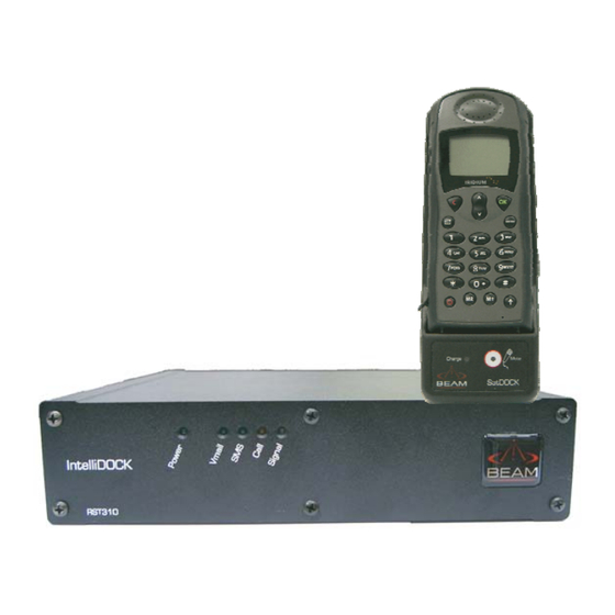
RST310 INSTALLATION & USER MANUAL About the RST310 The RST310 is a Remote Satellite Terminal docking station for the Iridium 9505A Handheld Satellite Telephones. Once the handset is docked in the SatDOCK Cradle it provides a reliable and cost effective telephone or data service connection when a wired connection is not available. -
Page 9: Rst310 Overview
RST310 INSTALLATION & USER MANUAL RST310 Overview The Front Panel Status LEDs Power Voicemail waiting* SMS waiting Call status Signal strength * Subject to network availability The Rear Panel Rear Connectors SatDOCK Connection 11-32V DC Power Input RJ11 / POTS Output (Accessory / External ringer) RJ11 / POTS Output (Main) Intelligent Handset or In-Vehicle Accessory connection Comm Port for data connectivity... - Page 10 RST310 INSTALLATION & USER MANUAL The RST310 Status Indicators The status indicators are located on the front panel of the RST310. The LED lights on the front panel show the RST310 status. Note: The LEDs will blink in different combinations to indicate transmission status, signal strength and power.
-
Page 11: Getting Started
RST310 INSTALLATION & USER MANUAL Getting Started What is a SIM Card? A SIM Card is a Subscriber Identity Module (computer chip) that contains identity information for accessing the Iridium network. It functions as the digital memory of the RST310 and also stores your personal information, including received SMS messages. -
Page 12: Installation Procedure
RST310 INSTALLATION & USER MANUAL Installation procedure 1. Mount the RST310 2. Connect AC/DC Power cord 3. Connect SatDOCK cable 4. Fitting antenna adapter/external antenna 5. Connect a Laptop/PC 6. Connect RJ11 telephone handset 7. Power Up & Make/Receive calls 1. - Page 13 RST310 INSTALLATION & USER MANUAL Option A: The main terminal can be mounted with the SatDOCK cradle in a separate location or on a separate mounting structure. 1. Attach the two (2) mounting brackets securely to a suitable structure making sure the space between the brackets is wide enough to smoothly slot in the RST310.
- Page 14 RST310 INSTALLATION & USER MANUAL Option B: Using the brackets supplied the Ram-mount handset holder can be firmly attached to the terminal as pictured below, follow the above instructions for mounting the terminal, however using the longer mounting screws supplied affix the additional ram- mount holding bracket to the side of the unit.
-
Page 15: Connecting The Power Cable
RST310 INSTALLATION & USER MANUAL 2. Connecting the Power Cable 1. Make sure the AC power switch supplying the RST310 power pack is off. 2. Plug in the power cable into the power jack located on the rear panel of the RST310. -
Page 16: Connecting An Rj11 Telephone Handset
RST310 INSTALLATION & USER MANUAL 4. Connecting an RJ11 telephone handset 1. Plug the telephone, answering machine or corded/cordless phone into the Line and or Accessory Socket RJ11. It is important to note that Facsimile Messaging is not supported on the Iridium Network via a standard RJ11 connection. -
Page 17: Connecting The Antenna Cable & Interface Cable
RST310 INSTALLATION & USER MANUAL 5. Connecting the Antenna Cable & Interface Cable The Antenna adaptor is required to be connected to the SatDOCK cradle as the 9505A handset will use the external antenna whilst seated in the SatDOCK cradle. To attach the antenna adaptor follow these steps: Connect the SMA / TNC adapter to the Antenna Cable. -
Page 18: Docking / Undocking The 9505A Handset
RST310 INSTALLATION & USER MANUAL 6. Docking / Undocking the 9505A handset To dock the 9505A handset into the SatDOCK cradle, firstly ensure that you remove the rotating antenna from the handset. Refer to your 9505A handsets’ user manual if you are unsure on how to do this. -
Page 19: Decoded Antenna Orientation
RST310 INSTALLATION & USER MANUAL 6.1 Decoded antenna orientation: Some earlier firmware versions of the 9505A handsets may display a message prompting the user to rotate the antenna if it is removed to be placed in the SatDOCK, and the user is unable to do anything further. To Toggle between enabling / disabling this message, refer to the following instructions: 1. -
Page 20: Mute Function
RST310 INSTALLATION & USER MANUAL 7. Mute Function Mute functionality: The mute function of the SatDOCK, allows the user to mute all audio to the 9505A handset whilst docked in the SatDOCK, by simply pressing the Mute button on the face of the SatDOCK. -
Page 21: Connecting A Laptop/Pc
RST310 INSTALLATION & USER MANUAL 8. Connecting a Laptop/PC 1. Plug the laptop cable into the Comm.’s port of the RST310. 2. Refer to the Beam Data Guide for more information on accessing Iridium data services with your RST310. 9. Connecting to the Log Port 1. -
Page 22: Making A Phone Call
RST310 INSTALLATION & USER MANUAL Making a phone call Logging on to Iridium Network With the power turned on, the RST310 will attempt to register with the Iridium network. The Signal LED uses colours to indicate how strong the Iridium signal is at your location. -
Page 23: Accessing Vmail And Sms On Your Rst310
RST310 INSTALLATION & USER MANUAL Accessing Vmail and SMS on your RST310 Voicemail When a Voicemail message has been received by the RST310 the Vmail LED will flash. The LED will stop flashing when the message has been cleared when the user connects to the Voicemail retrieval number programmed in the RST310. -
Page 24: Connecting Your Rst310 With A Pabx
RST310 INSTALLATION & USER MANUAL Connecting your RST310 with a PABX The RST310 RJ11 port presents as an FXS line, that is it looks like an exchange or central office line to a standard DTMF telephone attached to the RJ11 analog port. If instead of a standard telephone, a PABX is connected, then the RST310 is performing the role of the network trunk as shown below: Call Progress... - Page 25 RST310 INSTALLATION & USER MANUAL Configuring the RJ11 port parameters The ability to configure the RJ11 port parameters is one of the major features of the RST310. Port parameters can be configured using the BEAM Management System (BMS). The BMS allows the configuration of: •...
- Page 26 RST310 INSTALLATION & USER MANUAL Using an SMS-POTS telephone connected to an RST310 enables the handset to be run long distances from the RST310 over whilst still supporting SMS. Typically the Intelligent type handsets are limited to less than 10m/30’ whereas the SMS-POTS being on the RJ11 line will support 100s metres / 1000s feet.
-
Page 27: Remote Configuration
RST310 INSTALLATION & USER MANUAL Remote Configuration The Supervisor Menu items are available for remote configuration via a combination of the Iridium Short Burst Data and or SMS services. Refer to your Service Provider on how to register for this service. To configure your RST remotely you will need to know its Phone Number, Supervisor PIN and International Mobile Equipment Identifier (IMEI) number. -
Page 28: Accessories & Options
RST310 INSTALLATION & USER MANUAL Accessories & Options BEAM RST970: Intelligent Handset The RST310 is capable of supporting voice services on the Iridium network through the use of an (optional) Intelligent handset. This Intelligent Handset enables you to access Voice and SMS services over the Iridium network in conjunction with the RST310. - Page 29 RST310 INSTALLATION & USER MANUAL Symbols on the Intelligent Handset versus the 9505A Please note that all the symbols do not correspond, and use the following table to interpret what is being indicated on the Intelligent Handset: Symbol 9505A Intelligent Handset Not Used Not Used 9505A Display...
-
Page 30: Specification Summary
RST310 INSTALLATION & USER MANUAL Specification Summary Electrical Power 11-32V DC 2.5A Plug-pack (if provided) 90-250VAC 50/60Hz input Power Consumption Input Voltage (Average Current) Standby Mode 0.35A 0.16A Talk/Transmit Mode 0.52A 0.26A Subscriber Line Interface Ring Equivalence Number 3 REN 600 Ω... -
Page 31: Rs232 Specification
RST310 INSTALLATION & USER MANUAL RS232 Specification The RST-100 is provided with two RS232 serial ports for log and data connection. Both are 9-pin D-type (female) sockets, wired DCE for connection to a standard PC with a 1:1 cable. Physical Connection The pin-out of both connectors is described in the following table: Signal Direction... - Page 32 RST310 INSTALLATION & USER MANUAL RS232 Port Signal Support and Handshaking On the data logging port, DCD and DSR output signals are related to DTR input and CTS is tied to RTS as shown. The Data port supports full software XON/XOFF handshaking on data (AT commands bypass this as standard for Hayes modems) or full hardware handshaking on RTS/CTS with DCD carrier indication.
-
Page 33: Troubleshooting
RST310 INSTALLATION & USER MANUAL Troubleshooting This chapter provides information to help you troubleshoot problems you may encounter while running the RST310. No lights on RST310 Check power is connected and switched on at the wall. Low earpiece volume on handsets Ensure the 9505A handheld volume control is set to maximum using the volume buttons on the side of the handset. - Page 34 RST310 INSTALLATION & USER MANUAL Check your Operator coverage map. Is Restricted displayed? Check the Call Barring setting. You can’t receive calls Check to see that your phone is powered on. Check the antenna. Is it properly mounted? Do you have a clear view of the sky? Check the signal strength.
-
Page 35: Beam Warranty Conditions
RST310 INSTALLATION & USER MANUAL BEAM Warranty Conditions BEAM Communications gives this express warranty (along with extended warranty endorsements, where applicable) in lieu of all other warranties, express or implied, including (without limitation), warranties of merchantability and fitness for a particular purpose. This constitutes our sole warranty and obligation with regard to our products as well as the Customer’s sole remedy.
Need help?
Do you have a question about the IntelliDOCK RST310 9505A and is the answer not in the manual?
Questions and answers