Beam RST310 Installation And User Manual
9505a intellidock docking station
Hide thumbs
Also See for RST310:
- Installation and user manual (58 pages) ,
- Installation and user manual (35 pages) ,
- Installation and user manual (34 pages)

Related Manuals for Beam RST310


Summary of Contents for Beam RST310
-
Page 1: Docking Station
RST310 9505A IntelliDOCK Docking Station Installation and User Manual Beam Communications Pty. Ltd. - Page 2 Beam. Beam reserves the right to change specifications at any time without notice. Copyright © 2007 Beam Communications Pty Ltd. All rights reserved Product name: RST310 Installation & User Manual Manual revision: 05 Part Number: USRMAN001605...
-
Page 3: Package Contents
RST310 INSTALLATION & USER MANUAL Package Contents The RST310 package contains: 1 x RST310 unit 1 x Universal plug-pack power adapter, 110-240V AC 1 x 9-pin-to-9-pin RS-232 cable (Male to Female) 1 x User manual (Printed) 1 x Ram Mount Bracket... -
Page 4: User Information
Model: RST310 Serial no.: This number can be copied from the white shipping label on the RST310 box Eg. 100A2800 The following PIN codes may be required to use your RST310, please complete these details for future reference. Your SIM and their PINs are related to the handset. -
Page 5: Table Of Contents
OGGING ON TO RIDIUM ETWORK ......................... 22 AKING A PHONE CALL RST310..................23 CCESSING MAIL AND ON YOUR CONNECTING YOUR RST310 WITH A PABX..................24 ........................27 EMOTE ONFIGURATION ACCESSORIES & OPTIONS ....................... 28 BEAM RST970: I ....................28 NTELLIGENT ANDSET SPECIFICATION SUMMARY ....................... -
Page 6: Safety Information
Please consult your supplier if you have any further questions. Your RST310 is a low power radio transmitter and receiver. When it is ON, it receives and sends out radio frequency (RF) signals. The design of your RST310 system complies with international safety standards. -
Page 7: About Beam Communications
RST310 INSTALLATION & USER MANUAL About BEAM Communications BEAM Communications, is an authorised manufacturer of Iridium Satellite products. BEAM develops subscriber products that utilise the Iridium satellite network of Low Earth Orbit satellites, known as LEOs. The Iridium network is extensively used around the world by commercial enterprises and defence agencies. -
Page 8: About The Rst310
The RST310 provides a serial control interface and audio input and outputs by way of the transceiver’s control and connection interface. -
Page 9: Rst310 Overview
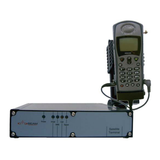
RST310 INSTALLATION & USER MANUAL RST310 Overview The Front Panel Status LEDs Power Voicemail waiting* SMS waiting Call status Signal strength * Subject to network availability The Rear Panel Rear Connectors 9505A Connection 11-32V DC Power Input RJ11 / POTS Output (Accessory / External ringer) -
Page 10: The Rst310 Status Indicators
RST310 INSTALLATION & USER MANUAL The RST310 Status Indicators The status indicators are located on the front panel of the RST310. The LED lights on the front panel show the RST310 status. Note: The LEDs will blink in different combinations to indicate transmission status, signal strength and power. -
Page 11: Getting Started
A SIM Card is a Subscriber Identity Module (computer chip) that contains identity information for accessing the Iridium network. It functions as the digital memory of the RST310 and also stores your personal information, including received SMS messages. SIM Card Protection Handle the SIM card with care, avoid exposing the card to static electricity, water or dirt. -
Page 12: Installation Procedure
6. Connect RJ11 telephone handset 7. Power Up & Make/Receive calls 1. Mounting the RST310 The RST310 comes with two (2) standard right angle mounting brackets that allow mounting for mobile and fixed positioning. Note: To ensure sturdy mount attachment: 1. - Page 13 RST310. 2. Secure the RST310 unit to the mounting brackets using supplied screws. 3. Carefully slot the RST310 between the two mounting brackets and secure with the retaining screws. 4. Mount the Ram-mount cradle for the 9505A in the desired location ensuring that there is sufficient cable length for the handset to connect to the main terminal.
- Page 14 RST310 INSTALLATION & USER MANUAL Option B: Using the brackets supplied the Ram-mount handset holder can be firmly attached to the terminal as pictured below, follow the above instructions for mounting the terminal, however using the longer mounting screws supplied affix the additional ram- mount holding bracket to the side of the unit.
-
Page 15: Connecting The Power Cable
RST310 INSTALLATION & USER MANUAL 2. Connecting the Power Cable 1. Make sure the AC power switch supplying the RST310 power pack is off. 2. Plug in the power cable into the power jack located on the rear panel of the RST310. -
Page 16: Connecting An Rj11 Telephone Handset
RST310 INSTALLATION & USER MANUAL 4. Connecting an RJ11 telephone handset 1. Plug the telephone, answering machine or corded/cordless phone into the Line and or Accessory Socket RJ11. It is important to note that Facsimile Messaging is not supported on the Iridium Network via a standard RJ11 connection. - Page 17 RST310 INSTALLATION & USER MANUAL Removing the Antenna from the 9505A handset 1. Ensure the antenna is facing down and completely retracted 2. Holding the 9505A handheld firmly press down on antenna release button 3. Whilst holding down the release button firmly, remove the antenna from the connection gently.
-
Page 18: Decoded Antenna Orientation
RST310 INSTALLATION & USER MANUAL 5.1 Decoded antenna orientation: To operate this phone with the antenna in the DECODED orientation (above) for enhanced user convenience, the95095A handset settings need changing. 1. With the phone turned ON enter the following code: * # 92 # 2. - Page 19 RST310 INSTALLATION & USER MANUAL Checking Performance after Installation To confirm that the phone is working properly, follow the instructions in this section. 1. Make a call from the handset in the cradle and confirm operation. 2. Make a call to the handset and confirm operation.
-
Page 20: Connecting A Laptop/Pc
The 9505A unit will now power on in Hands free mode. If it continues to exhibit out of the ordinary operations please repeat the above process. 6. Connecting a Laptop/PC 1. Plug the laptop cable into the Comm.’s port of the RST310. -
Page 21: Connecting To The Log Port
RST310 INSTALLATION & USER MANUAL 7. Connecting to the Log Port 1. Connect the laptop to the Log port. The Log port should only be used for configuration and control of the terminal equipment. The LOG port can not be used for Communications or Data Services 2. -
Page 22: Making A Phone Call
Making a phone call Logging on to Iridium Network With the power turned on, the RST310 will attempt to register with the Iridium network. The Signal LED uses colours to indicate how strong the Iridium signal is at your location. -
Page 23: Accessing Vmail And Sms On Your Rst310
Voicemail retrieval number programmed in the RST310. SMS - Short Message Service When an SMS has been sent to the RST310, the SMS LED will flash. This means that the SMS is ready to be read. The indicator is cleared when the SMS has been read and cleared from the RST310 memory. -
Page 24: Connecting Your Rst310 With A Pabx
RST310 INSTALLATION & USER MANUAL Connecting your RST310 with a PABX The RST310 RJ11 port presents as an FXS line, that is it looks like an exchange or central office line to a standard DTMF telephone attached to the RJ11 analog port. -
Page 25: Configuring The Rj11 Port Parameters
• Gain settings (to allow optimisation for short and long copper tails up to 500m) • Impedance (to accommodate a large range of terminals equipment including PBXs) This ability to adapt the RST310 to particular applications opens up new areas of use o crew calling o rural community centres o SOHO use o Universal Service Obligation activities. -
Page 26: Data Settings Auto Answer
SMS-POTS service. Data Settings Auto Answer To initialise the RST310 to receive an incoming data call, start a Terminal Program (such as HyperTerminal) with the following settings: 19200* bps, 8, N, 1, Flow Control = None... -
Page 27: Remote Configuration
RST310 INSTALLATION & USER MANUAL Remote Configuration The Supervisor Menu items are available for remote configuration via a combination of the Iridium Short Burst Data and or SMS services. Refer to your Service Provider on how to register for this service. -
Page 28: Accessories & Options
RST310 INSTALLATION & USER MANUAL Accessories & Options BEAM RST970: Intelligent Handset The RST310 is capable of supporting voice services on the Iridium network through the use of an (optional) Intelligent handset. This Intelligent Handset enables you to access Voice and SMS services over the Iridium network in conjunction with the RST310. -
Page 29: Specification Summary
RST310 INSTALLATION & USER MANUAL Specification Summary Electrical Power 11-32V DC 2.5A Plug-pack (if provided) 90-250VAC 50/60Hz input Power Consumption Input Voltage (Average Current) Standby Mode 0.35A 0.16A Talk/Transmit Mode 0.52A 0.26A Subscriber Line Interface Ring Equivalence Number 3 REN Impedance 600 Ω... -
Page 30: Rs232 Specification
RST310 INSTALLATION & USER MANUAL RS232 Specification The RST-100 is provided with two RS232 serial ports for log and data connection. Both are 9-pin D-type (female) sockets, wired DCE for connection to a standard PC with a 1:1 cable. Physical Connection... - Page 31 RST310 INSTALLATION & USER MANUAL RS232 Port Signal Support and Handshaking On the data logging port, DCD and DSR output signals are related to DTR input and CTS is tied to RTS as shown. The Data port supports full software XON/XOFF handshaking on data (AT commands bypass this as standard for Hayes modems) or full hardware handshaking on RTS/CTS with DCD carrier indication.
-
Page 32: Troubleshooting
This should be automatically adjusted during a call to maximum volume. RST310 fails to register with the Iridium service after 30 seconds Press reset button, ensure 9505A handheld is powered on and cables... - Page 33 RST310 INSTALLATION & USER MANUAL Check the antenna. Is it properly mounted? Do you have a clear view of the sky? Check the signal strength. If the signal is weak, move the vehicle to a more open area. Check the Call Forwarding and Call Barring settings.
-
Page 34: Beam Warranty Conditions
RST310 INSTALLATION & USER MANUAL BEAM Warranty Conditions BEAM Communications gives this express warranty (along with extended warranty endorsements, where applicable) in lieu of all other warranties, express or implied, including (without limitation), warranties of merchantability and fitness for a particular purpose. This constitutes our sole warranty and obligation with regard to our products as well as the Customer’s sole remedy.
Need help?
Do you have a question about the RST310 and is the answer not in the manual?
Questions and answers