Table of Contents
Advertisement
Quick Links
Download this manual
See also:
User Manual
ALI-NVR5000P Series Embedded Network Video Recorder Quick Setup Guide
This quick setup guide provides instructions to initially setup and use the ALI-NVR5016P and ALI-NVR5032P network video recorders (NVRs).
For additional information on the extensive capabilities of your NVR, refer to the ALI-NVR5000P Series Embedded Network Video
Recorder User Manual provided electronically with your system.
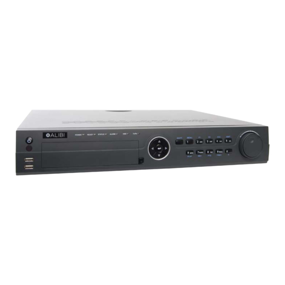
NVR Front Panel
Power and USB Ports (2)
Status indicators
ALI-NVR5016P NVR front panel
Name
Function / Description
POWER
Turns green when NVR is powered up.
Status Indicators
READY
The indicator is green when the device is running normally.
The light is green when the IR remote control is enabled;
STATUS
The light is red when the function of the composite keys (SHIFT) are used;
The light is out when none of the above condition is met.
Status Indicators
ALARM
The light is red when there is an alarm occurring.
(cont.)
HDD
Blinks red when HDD is reading/writing.
Tx/Rx
Blinks green when network connection is functioning normally.
In menu mode, the direction buttons are used to navigate between different fields and items and select setting parameters.
In playback mode, the Up and Down buttons are used to speed up and slow down record playing, and the Left and Right buttons
DIRECTION
are used to move the recording 30s forwards or backwards.
In the image setting interface, the up and down button can adjust the level bar of the image parameters.
In live view mode, these buttons can be used to switch channels.
Control Buttons
The Enter button is used to confirm selection in menu mode; or used to check checkbox fields and ON/OFF switch.
In playback mode, it can be used to play or pause the video.
ENTER
In single-frame play mode, pressing the Enter button will play the video by a single frame.
In auto sequence view mode, the buttons can be used to pause or resume auto sequence.
Switch between the numeric or letter input and functions of the composite keys. (Input letter or numbers when the light is out;
SHIFT
Realize functions when the light is red.)
Enter numeral "1";
1/MENU
Access the main menu interface.
Enter numeral "2";
2/ABC/F1
Enter letters "ABC";
Composite Keys
The F1 button when used in a list field will select all items in the list.
Enter numeral "3";
Enter letters "DEF";
3/DEF/F2
The F2 button is used to change the tab pages.
In PTZ control mode, it zooms in the image.
Enter numeral "4";
Composite Keys
4/GHI/ESC
Enter letters "GHI";
(cont.)
Exit and back to the previous menu.
1
Control Buttons
Composite keys
Jog Shuttle control
Name
Function / Description
Enter numeral "5";
Enter letters "JKL";
5/JKL/EDIT
Delete characters before cursor;
Check the checkbox and select the ON/OFF switch;
Start/stop record clipping in playback.
Enter numeral "6";
6/MNO/PLAY
Enter letters "MNO";
Playback, for direct access to playback interface.
Enter numeral "7";
7/PQRS/REC
Enter letters "PQRS";
Composite Keys
Open the manual record interface.
(cont.)
Enter numeral "8";
8/TUV/PTZ
Enter letters "TUV";
Access PTZ control interface.
Enter numeral "9";
9/WXYZ/
Enter letters "WXYZ";
PREV
Multi-channel display in live view.
Enter numeral "0", or letter "A"
0/A
Shift the input methods in the editing text field. (Upper and lowercase, alphabet, symbols or numeric input).
Pess the button twice to switch the main and auxiliary output.
Move the active selection in a menu. It will move the selection up and down.
In Live View mode, it can be used to cycle through different channels.
JOG SHUTTLE Control
In the Playback mode, it can be used to jump 30s forward/backward in video files.
In PTZ control mode, it can control the movement of the PTZ camera.
POWER ON/OFF
Power on/off switch.
USB Interfaces
Universal Serial Bus (USB) ports for additional USB devices such as a mouse or Hard Disk Drive (HDD).
NVR Backpanel
eSata
RS-232
Monitor Out (HDMI, VGA, CVBS)
Camera Channels (POE)
Audio OUT
Item
Description
eSATA
Connects external SATA HDD, CD/DVD-RW.
RS-232 Interface
DB9 (male) connector for RS-232 devices
CVBS - BNC connector for video output
VGA - DB15 connector for VGA compatible monitor. Supports 1920 × 1080p @ 60 Hz, 1600 × 1200 @ 60 Hz,
VIDEO OUT
1280 × 1024 @ 60 Hz, 1280 × 720 @ 60 Hz/, 1024 × 768 @ 60 Hz
(CVBS, VGA, HDMI)
HDMI - HDMI connector for an HDMI compatible monitor. Supports 1920 × 1080p @ 60 Hz, 1600 × 1200 @ 60 Hz,
1280 × 1024 @ 60 Hz, 1280 × 720 @ 60 Hz/, 1024 × 768 @ 60 Hz
LINE IN
BNC connector for audio input.
RS-485, Alarms IN / OUT
Power connector
LAN
USB
Ground
Fan outlet
ON / OFF switch
ALI-NVR5016P_SQ
6/30/14
Advertisement
Table of Contents

Related Manuals for ALIBI ALI-NVR5000P Series


Summary of Contents for ALIBI ALI-NVR5000P Series
- Page 1 This quick setup guide provides instructions to initially setup and use the ALI-NVR5016P and ALI-NVR5032P network video recorders (NVRs). Name Function / Description For additional information on the extensive capabilities of your NVR, refer to the ALI-NVR5000P Series Embedded Network Video Enter numeral “5”; Recorder User Manual provided electronically with your system.
-
Page 2: Remote Control
Remote Control Item Description RS-485, ALARMS IN/OUT See below. The enter key on the remote control or the front panel has the same function as a mouse left click. The IR Range of the remote control is 10 AC 100V ~ 240V AC 100 V ~ 240 V power supply. -
Page 3: Mouse Control
Mouse Control A standard 3-button (left/right/scroll-wheel) USB mouse can also be used with this NVR. To use a USB mouse: Plug USB mouse into the either the front panel or backpanel USB connector of the NVR. The mouse will be automatically detected. If the mouse is not detected, the mouse may not be compatible with the NVR. Please refer Switch to Backspace to the recommended device list from your provider. -
Page 4: Install A Monitor, Mouse, Power
Step 3. Using the Wizard for basic configuration setup AC load alarm output circuits Power on the NVR. Normally, an Alibi logo splash screen appears within 2 minutes. A secondary flash screen will appear showing the status of the HDDs installed in the NVR. - Page 5 Confirm fields. After the Alibi splash screen appears (see above), the NVR will check the status of HDDs installed within the chassis, and show the show icons on the screen indicating their status. A green check mark on the icon indicates that the associated HDD is operating normally.
- Page 6 (select no options). The recording mode of individual cameras can be configured using the menus in the firmware. See the ALI-NVR5000P Series Embedded Network Video Recorder User Manual for more information. Click Next after you configured the network parameters. The HDD management Wizard window will open. If a new DVR is shipped with a pre-configured HDD, nothing needs to be done in this window.
-
Page 7: Step 4. Access The Menu System
Click the star for Continuous or Motion Detection, click Yes in the Attention pop-up window, and then click OK to save the settings. The Wizard will close and the NVR will present the Live View display. See the ALI-NVR5000P Series Embedded Network Video Recorder User Manual for more information. -
Page 8: Specifications
Aluminum Approvals CE, FCC, RoHS For additional information about using your system, refer to the ALI-NVR5000P Series Embedded Network Video Recorder User Manual provided electronically with your system. Remote Client System Requirements Microsoft Windows 2000, 2003, XP, Vista, 7, 8 (32-bit and 64-bit version) / Linux 2.6+ / Operating System Apple MacOS X 10.5 (Intel x86 only), 10.6 and 10.7...
Need help?
Do you have a question about the ALI-NVR5000P Series and is the answer not in the manual?
Questions and answers