Table of Contents
Advertisement
Quick Links
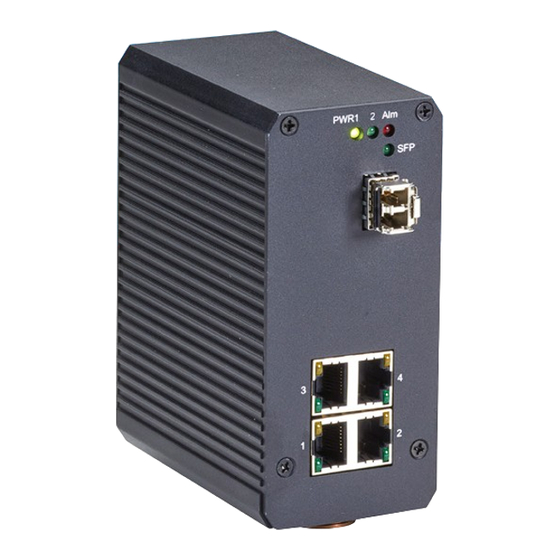
Hardened Ethernet PoE Switch, (4) 10/100/1000 Mbps, (1) GE S
User Manual
• LPH1000 Series Switches operate in harsh environments.
• Two power inputs connect simultaneously to live DC power sources.
• Alarm alerts you when power fails or a port disconnects.
Order toll-free in the U.S.: Call 877-877-BBOX (outside U.S. call 724-746-5500)
Customer
FREE technical support 24 hours a day, 7 days a week: Call 724-746-5500 or fax 724-746-0746
Support
Mailing address: Black Box Corporation, 1000 Park Drive, Lawrence, PA 15055-1018
Information
Web site: www.blackbox.com • E-mail: info@blackbox.com
BLACK BOX
LPH1004A
FP
®
Advertisement
Table of Contents

Subscribe to Our Youtube Channel
Related Manuals for Black Box LPH1004A


Summary of Contents for Black Box LPH1004A
-
Page 1: Black Box
Order toll-free in the U.S.: Call 877-877-BBOX (outside U.S. call 724-746-5500) Customer FREE technical support 24 hours a day, 7 days a week: Call 724-746-5500 or fax 724-746-0746 Support Mailing address: Black Box Corporation, 1000 Park Drive, Lawrence, PA 15055-1018 Information Web site: www.blackbox.com • E-mail: info@blackbox.com... - Page 2 Disclaimer: Black Box Network Services shall not be liable for damages of any kind, including, but not limited to, punitive, consequential or cost of cover damages, resulting from any errors in the product information or specifications set forth in this document and Black Box Network Services may revise this document at any time without notice.
- Page 3 FCC and IC RFI Statements Federal Communications Commission and Industry Canada Radio Frequency Interference Statements This equipment generates, uses, and can radiate radio-frequency energy, and if not installed and used properly, that is, in strict accordance with the manufacturer’s instructions, may cause inter ference to radio communication. It has been tested and found to comply with the limits for a Class A computing device in accordance with the specifications in Subpart B of Part 15 of FCC rules, which are designed to provide reasonable protection against such interference when the equipment is operated in a commercial environment.
-
Page 4: Instrucciones De Seguridad
NOM Statement Instrucciones de Seguridad (Normas Oficiales Mexicanas Electrical Safety Statement) 1. Todas las instrucciones de seguridad y operación deberán ser leídas antes de que el aparato eléctrico sea operado. 2. Las instrucciones de seguridad y operación deberán ser guardadas para referencia futura. 3. -
Page 5: Table Of Contents
Table of Contents Table of Contents 1. Specifications ..................................6 2. Overview ....................................8 2.1 Description ..................................8 2.2 Features ..................................8 2.3 What’s Included ................................8 2.4 Hardware Description ..............................9 3. Installation ................................... 11 3.1 Din Rail Mounting................................11 3.2 Hardware Installation ..............................12 3.2.1 Wiring the DC Power Inputs.......................... -
Page 6: Specifications
Chapter 1: Specifications 1. Specifications Alarm Contact One relay output with current carrying capacity of 1A @ 24 VDC Approvals FCC Part 15, Subpart B, Class A; UL60950-1 2nd Ed./CSA C22.2 No. 60950-1-07 2nd Ed.; CE (EMI): EN55022 Class A, FCC Part 15, Class A; CE (EMS): EN61000-4-2 (ESD), EN61000-4-3 (RS),... - Page 7 Chapter 1: Specifications Specifications (continued) Power Removable 6-pin terminal block, redundant inputs; Input: 12–48 VDC, 3.36 Watts maximum; RJ-45 ports: Power over Ethernet (PoE): IEEE 802.3at compliant (IEEE 802.3af compatible), up to 30 W per port, 120 W per system NOTE: Includes reverse polarity protection.
-
Page 8: Overview
Your package includes one Hardened Ethernet Switch. It has (4) 10-/100-/1000-Mbps twisted-pair ports and (1) 1000-Mbps Gigabit SFP slot. This user manual/installation guide can be downloaded from the Black Box Web site, or the FTP site. To download from the Web site: 1. -
Page 9: Hardware Description
Chapter 2: Overview 2.4 Hardware Description The front panel of the Gigabit Ethernet Switch is shown in Figure 2-1. The bottom panel is shown in Figure 2-2. 1 2 3 Figure 2-1. Front panel of the switch. Figure 2-2. Bottom panel of the switch. Go to the next page for a description of the switch components shown in the diagrams above. - Page 10 Chapter 2: Overview Table 2-1. Hardened Ethernet Switch components. Number in Figure 2-1 Component Description or 2-2 (1) Power 1 LED Lights green when power input 1 is ON; Off when no power is being supplied (1) Power 2 LED Lights when power input 2 is ON;...
-
Page 11: Installation
Chapter 3: Installation 3. Installation 3.1 DIN Rail Mounting The DIN-Rail clip already attached on the rear side of the switch supports an EN 50022 standard DIN Rail as shown in Figure 3-1. Spring DIN rail DIN rail clipper 1.35" (3.5 cm) 0.295"... -
Page 12: Hardware Installation
Chapter 3: Installation 3.2 Hardware Installation 3.2.1 Wiring the DC Power Inputs Before installing the power input, make sure the DC power supply complies with standard power supply certifications. NOTE: Suitable wire gauge is from 12 to 24 AWG. Follow these steps to wire the DC power cable to the connector: 1. -
Page 13: Wiring Earth Grounding
Chapter 3: Installation 3.2.3 Wiring Grounding AC motors, electric welding machines, and power devices generate electromagnetic and disturb communications. To prevent noise, be sure to ground the switch. The following diagram shows how to create a connection. Alarm system Maximum 1 A current, 24 VDC Extra power system Figure 3-4. -
Page 14: Cabling
Chapter 3: Installation 3.2.5 Cabling Ethernet Cabling: Ports 1–4 use copper UTP/STP cable. Table 3-2. Cable types for data transmision. Description 10BASE-T: 2-pair UTP/STP CAT3, 4, 5 cable, EIA/TIA-568, 100-ohm, Max. 328 feet (100 m) 100BASE-TX: 2-pair UTP/STP CAT5 cable, EIA/TIA-568, 100-ohm, Max. 328 feet (100 m) 1000BASE-T: 4-pair UTP/STP CAT5 cable, EIA/TIA-568, 100-ohm, Max. -
Page 15: System Diagnostics
Chapter 4: System Diagnostics 4. System Diagnostics Do a ping test to make sure the installation is correct. Ping 192.168.1.1 Ping 192.168.1.1 Target device PC host IP address: IP address: Ethernet cable Ethernet cable 192.168.1.1 192.168.1.10 Reply to 192.168.1.10 Reply to 192.168.1.10 Power Supply Figure 4-1. - Page 16 Chapter 4: System Diagnostics 2. Type “ping 192.168.1.1” command in the command window. The PC host (192.168.1.10) will then ping the target PC. The screen below shows the result you will get if you successfully ping the target IP address, for example 192.168.1.1. ...
- Page 17 NOTES 724-746-5500 | blackbox.com Page 17...
- Page 18 NOTES 724-746-5500 | blackbox.com Page 18...
- Page 19 NOTES 724-746-5500 | blackbox.com Page 19...
- Page 20 About Black Box Black Box provides an extensive range of networking and infrastructure products. You’ll find everything from cabinets and racks and power and surge protection products to media converters and Ethernet switches all supported by free, live 24/7 Tech support available in 60 seconds or less.
Need help?
Do you have a question about the LPH1004A and is the answer not in the manual?
Questions and answers