Table of Contents
Advertisement
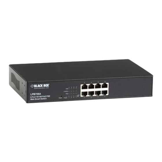
8-/16-/24-Port 10/100 PoE PSE Web Smart Switch
Connect VoIP phones, IP cameras, or any PoE PD
devices through manageable, switched links.
Complies with 802.af Power-over Ethernet standard.
Supports Web-based configuration and management.
Uses Auto-MDI/MDI-X so you can use crossover
or straight-through cables.
Automatically determines port speed.
Housed in a desktop metal case
with an internal power supply.
Includes PoE ON/OFF remote control.
LPB708A
LPB716A
LPB724A
Advertisement
Table of Contents

Subscribe to Our Youtube Channel
Related Manuals for Black Box LPB708A


Summary of Contents for Black Box LPB708A
- Page 1 LPB708A LPB716A LPB724A 8-/16-/24-Port 10/100 PoE PSE Web Smart Switch Connect VoIP phones, IP cameras, or any PoE PD devices through manageable, switched links. Complies with 802.af Power-over Ethernet standard. Supports Web-based configuration and management. Uses Auto-MDI/MDI-X so you can use crossover or straight-through cables.
- Page 2 8-/16-/24-Port 10/100 PoE PSE Web Smart Switch Federal Communications Commission and Industry Canada Radio Frequency Interference Statements This equipment generates, uses, and can radiate radio-frequency energy, and if not installed and used properly, that is, in strict accordance with the manufacturer’s instructions, may cause interference to radio communication. It has been tested and found to comply with the limits for a Class A computing device in accordance with the specifications in Subpart J of Part 15 of FCC rules, which are designed to provide reasonable protection against such interference when the equipment is operated in a commercial environment.
- Page 3 NOM Statement and CE Directive Normas Oficiales Mexicanas (NOM) Electrical Safety Statement INSTRUCCIONES DE SEGURIDAD 1. Todas las instrucciones de seguridad y operación deberán ser leídas antes de que el aparato eléctrico sea operado. 2. Las instrucciones de seguridad y operación deberán ser guardadas para referencia futura. 3.
-
Page 4: Table Of Contents
8-/16-/24-Port 10/100 PoE PSE Web Smart Switch Table of Contents 1. Specifications ..................................6 Hardware Specifications ............................6 Management Software Specifications ........................7 2. Overview ..................................8 Introduction ................................8 Features ..................................8 What’s Included ..............................8 Front and Rear Panels ............................9 2.4.1 Front Panel...............................9 2.4.2 Back Panel ...............................9 LED Indicators ..............................10 3. - Page 5 Table of Contents Spanning Tree ..............................36 4.8.1 STP Bridge Setting ..........................36 4.8.2 STP Port Setting ............................37 Trunking ................................38 4.10 Backup/Recovery ..............................40 4.11 Miscellaneous Setting ............................40 4.12 Logout ................................41 5. Troubleshooting ................................42 6. IP Address Assignment..............................43 IP Address................................43 Subnet Mask .................................43 Default Gateway ..............................44 ................................45 724-746-5500 l www.blackbox.com...
-
Page 6: Specifications
Size: LPB708A: 1.7”H x 6.3”W x 10.5”D (4.4 x 16 x 26.6 cm); LPB716A, LPB724A: 1.7”H x 8.7”W x 17.3”D (4.4 x 22 x 44 cm) Weight: LPB708A: 3.5 lb. (1.6 kg); LPB716A: 7.9 lb. (3.6 kg); LPB724A: 8.6 lb. (3.9 kg) 724-746-5500 l www.blackbox.com... -
Page 7: Management Software Specifications
Chapter 1: Specifications Management Software Specifications Backup/Recovery Configuration IGMP Snooping: V1/V2 Port Management: Port Configuration, Port Mirroring, Bandwidth Control, Broadcast Strom Control, PoE On/ Off Setting QoS Setting: Up to 4 queues RSTP/STP: Rapid/Spanning Tree Protocol VLAN Function: Port-Based/802.1Q-Tagged, up to 256 active VLANs in one switch VLAN Setting: Port-based/Tag-based, VLAN ID: 1–4094K Security Filter: MAC address filtering, TCP/UDP filtering Trunking: 2 groups (1–4 ports for each group) -
Page 8: Overview
Security: Support MAC Address and TCP/UDP filtering to prevent unknown users or un-authorized actions connected to network. 2.3 What’s Included Your package should include the following items. If anything is missing or damaged, contact Black Box Technical Support at 724-746-5500 or info@blackbox.com. (1) 8-, or 16-, or 24-Port 10/100 PoE PSE Web Smart Switch (1) Mounting Accessory (for 19”... -
Page 9: Front And Rear Panels
8 RJ-45 TP ports LPB708A. LED Indicators (16) RJ-45 TP ports LPB716A. 2 Combo UTP/SFP LED Indicators 24 RJ-45 TP Ports Ports LPB724A. Figure 2-1. LPB708A, LPB716A, LPB724A Front panels. 2.4.2 Back Panel AC Power Input Figure 2-2. Back panel. 724-746-5500 l www.blackbox.com... -
Page 10: Led Indicators
8-/16-/24-Port 10/100 PoE PSE Web Smart Switch 2.5 LED Indicators LPB708A LPB716A LPB724A Figure 2-3. LED Indicators. 724-746-5500 l www.blackbox.com... - Page 11 Systems LED (All models) Power Green Lit when power is on Reset Used to restore management system 10/100 Ethernet TP Port 1 to 8 LEDs (LPB708A) LINK/ACT Green Blinks when any traffic is present Off when connection is not good Green...
-
Page 12: Installation
8-/16-/24-Port 10/100 PoE PSE Web Smart Switch 3. Installation 3.1 Hardware and Cable Installation CAUTION: Wear a grounding device to avoid damage from electrostatic discharge. Be sure that the power switch is OFF before you connect the power cord to the power source. 3.1.1 TP Port and Cable Installation 1. -
Page 13: Power On
Chapter 3: Installation 3.1.3 Power On The switch supports a 100-240 VAC, 50-60 Hz power supply. The power supply will automatically convert the local AC power source to DC power. It does not matter whether any connection is plugged into the switch or not when powering on. After the power is on, all LED indicators will light immediately and then all go off except the power LED, which stays on. -
Page 14: Switch Cascading In Topology
8-/16-/24-Port 10/100 PoE PSE Web Smart Switch 3.4 Switch Cascading in Topology Theoretically, the switch partitions the collision domain for each port in switch cascading so that you may uplink an unlimited number of switches. In practice, the network extension (cascading levels and overall diameter) must comply with the IEEE 802.3/802.3u and other 802.1 series protocol specifications, which limit the timing requirement from physical signals defined by the Media Access Control (MAC) and PHY802.3 series specification, and the timer from some OSI layer 2 protocols such as 802.1d, 802.1q, and LACP. - Page 15 Chapter 3: Installation Case2a: Port-based VLAN (See Figure 3-4). VLAN 1 VLAN 2 VLAN 3 VLAN 4 Figure 3-4. One switch connected to four VLANs in a port-based VLAN. 1. The same VLAN members can not be in different switches. 2.
-
Page 16: Set Ip Address, Subnet Mask, And Default Gateway Ip Address
For example, your network address is 10.1.1.0, and subnet mask is 255.255.255.0. You can change the switch’s default IP address 192.168.2.1 to 10.1.1.1 and set the subnet mask to 255.255.255.0. Then, choose your default gateway, for example, 10.1.1.254. Default Value LPB708A/LPB716A Your Network Setting IP Address 192.168.2.1 10.1.1.1... - Page 17 Chapter 3: Installation NOTE: If a PC directly connects to the switch, you have to setup the same subnet mask between them. But, subnet mask may be different for the PC at the remote site. See the following about the switch’s default IP address information. Default IP address: 192.168.2.1 Default ID: admin Default Password: admin...
-
Page 18: Operation Of Web-Based Management
8-/16-/24-Port 10/100 PoE PSE Web Smart Switch 4. Operation of Web-based Management This chapter instructs you how to configure and manage the switch through the web user interface it supports, to access and manage the switch. With this facility, you can easily access and monitor through any one port of the switch the status of the switch, including each port activity, Spanning tree status, port aggregation status, VLAN, and priority status and so on. -
Page 19: Web Management Home Overview
Chapter 6: IP Address Assignment In Figure 4-2, for example, the left section shows the whole function tree with web user. Each option is described in this chapter. Port Connection Status Configuration Content Screen Configuration Function Bar Figure 4-2. Layout of screen for web management. 4.1 Web Management Home Overview After you login, the screen shown in Figure 4-3 appears. -
Page 20: Authentication Configuration
8-/16-/24-Port 10/100 PoE PSE Web Smart Switch System Status Load Default Setting Firmware Update Reboot Device 4.2.1 Authentication Configuration Function name: Authentication Configuration Function description: Change the default login username (ID) or password. Parameter description: Username (ID): Type in the login name you’d like, the maximum characters are 15. Password: Type in the password you’d like, the maximum characters are 15. -
Page 21: System Status
Chapter 6: IP Address Assignment Figure 4-5. System IP Configuration screen. 4.2.3 System Status Function name: System Status Function description: Display the system information of the switch. Parameter description: MAC Address: The MAC address of this switch. Number of Ports: Show the port numbers of this switch. System Version: The system’s firmware version number. -
Page 22: Load Default Setting
8-/16-/24-Port 10/100 PoE PSE Web Smart Switch 4.2.4 Load Default Setting Function name: Load Default Setting Function description: Back to factory default settings of the switch. Parameter description: Click <Load> to back to the factory default setting. NOTE: Recover the switch default setting excluding the IP address, user name, and password. Figure 4-7. -
Page 23: Port Configuration
Chapter 6: IP Address Assignment 4.3.1 Port Configuration Function name: Port Configuration Function description: Configure each port’s speed, full- or half-duplex, and so on. Parameter description: Auto: Enable or disable Auto-Negotiation. Speed: 10M or 100M mode for the selected port. Duplex: 10M or 100M mode for the selected port. -
Page 24: Bandwidth Control
8-/16-/24-Port 10/100 PoE PSE Web Smart Switch Parameter description: Destination Port: Select the port for monitoring and the egress traffic will be copied to the monitoring port. Monitor Packets: Enable or Disable if you want to copy the packet from source port to destination port. Source Port: Select the port you want to monitor the traffic. -
Page 25: Broadcast Storm Control
Chapter 6: IP Address Assignment Figure 4-11. Bandwidth Control screen. 4.3.4 Broadcast Storm Control Function name: Broadcast Storm Control Function description: You can limit the bandwidth of received and transmitted frames to each port. Parameter description: Threshold: Set the threshold from 1–63. The threshold value is as follows. Connection Speed/ ….. -
Page 26: Vlan Setting
8-/16-/24-Port 10/100 PoE PSE Web Smart Switch Figure 4-13. PoE screen. 4.4 VLAN Setting The switch supports Tag-based VLAN (802.1Q) and Port-based VLAN. It supports 4094 active VLANs and VLAN ID 1– 4094. VLAN configuration is used to partition your LAN into small ones ad needed. By properly configuring it, you will impove security and increase performance but greatly reduce VLAN management. -
Page 27: Tag-Based Vlan1
Chapter 6: IP Address Assignment Figure 4-15. Port-based VLAN Member Setting screen. 4.4.3 Tag-based VLAN Function name: Tag-based VLAN Function description: When you enable tag-based VLAN, you need to configure the packet forwarding options first. Parameter description: Outgoing Packets: You can select one of three options to forward the packets. 724-746-5500 l www.blackbox.com... -
Page 28: Tag-Based Vlan-Vlan Member
8-/16-/24-Port 10/100 PoE PSE Web Smart Switch Figure 4-16. Tag-based VLAN screen. 4.4.4 Tag-based VLAN—VLAN Member Function name: VLAN Member Function description: When you enable tag-based VLAN, you need to configure VLAN members with each port. Parameter description: VID: Tag-based VLAN identifies its member by VID (VLAN ID). Each tag-based VLAN you build must be assigned a VLAN ID. -
Page 29: Multi To 2 Setting
Chapter 6: IP Address Assignment Figure 4-17. Tag-based VLAN Member Setting screen. 4.4.5 Multi to 2 Setting Function name: Multi to 2 Setting Function description: This sets the switch VLAN into “VLAN Per Port.“ When you enable this setting, all the original VLAN settings will be replaced by this method. -
Page 30: Per Port Counter
8-/16-/24-Port 10/100 PoE PSE Web Smart Switch Figure 4-18. Multi to 2 Setting screen. 4.5 Per Port Counter 4.5.1 Counter Category Function name: Counter Category Function description: You can read the transmitting and receiving packet of the connected ports in this screen. Parameter description: Current Mode Selection: Display the number of receive and transmit packets, transmit packets and collisions, receive packets and drop packets, or receive packets and CRC error. -
Page 31: Qos Setting
Chapter 6: IP Address Assignment Figure 4-19. Per Port Counter screen. 4.6 QoS Setting 4.6.1 Priority Mode Function name: Priority Mode Function description: This is the page that allows you to configure QoS (Quality of Service) to enhance network performance. This switch supports three types of QoS. Parameter description: Mode: There are three Priority Modes to select. -
Page 32: Class Of Service-Tcp/Udp
8-/16-/24-Port 10/100 PoE PSE Web Smart Switch 4.6.3 Class of Service— TCP/UDP Function name: TCP/UDP Port Function description: You need to configure the queue priority for each TCP and UDP service. Just select the priority queue by the service type you want to enable, and the switch also allow you to define three TCP/UDP queues. Figure 4-21. -
Page 33: Class Of Service-Ip Tos/Ds
Chapter 6: IP Address Assignment 4.6.4 Class of Service—IP TOS/DS Function name: IP TOS/DS (Type of Service/ Differential Service) Function description: When you enable this function, the packets with special IP will be transmitted first. The switch provides the IP layer CoS function by recognizing the DSCP (Differentiated Service Code Point) Octet and mapping it to the specified priority. -
Page 34: Class Of Service-Physical Port
8-/16-/24-Port 10/100 PoE PSE Web Smart Switch 4.6.6 Class of Service—Physical Port Function name: Physical Port Function description: Select the port that you want to configure as Q1–Q4 priority. Figure 4-24. Physical Port for CoS configuration. 4.7 Security This switch supports MAC Address and TCP/UDP filtering to prevent unauthorized users from connecting to the network. 4.7.1 MAC Address Configuration Function name: MAC Address Configuration Function description: Set the specified MAC address to be activated on the selected port. -
Page 35: Tcp/Udp Filter Configuration
Chapter 6: IP Address Assignment 4.7.2 TCP/UDP Filter Configuration Function name: TCP/UDP Filter Configuration Function description: This switch allows you to configure each port you want to limit or allow the TCP/UDP protocol type to get through, such as HTTP, FTP or TELNET and so on. Parameter description: Function Enable: Enable/ Disable this TCP/UDP Filter. -
Page 36: Spanning Tree
8-/16-/24-Port 10/100 PoE PSE Web Smart Switch Figure 4-26. TCP/UDP filtering configuration. 4.8 Spanning Tree 4.8.1 STP Bridge Settings Function name: STP Bridge Settings Function description: Spanning Tree can prevent network loops. For RING connections, you need to enable Spanning Tree to prevent loops. -
Page 37: Stp Port Setting
Chapter 6: IP Address Assignment Bridge Priority (0–61440): Usually, the bridge with the highest bridge priority is the root. If you want to have the switch as the root bridge, you can set this value lower than that of bridge in the LAN. The valid value is 0– 61440. -
Page 38: Trunking
8-/16-/24-Port 10/100 PoE PSE Web Smart Switch 802.1w RSTP recommended value: (Valid range: 1–200,000,000) 10 Mbps: 2,000,000 100 Mbps: 200,000 Figure 4-28. STP Port Settings screen. 4.9 Trunking The switch supports two kinds of port trunking methods, LACP and Static. Function name: Link Aggregation Settings Function description: There are two groups to choose from and the maximum for each group is 4 ports. - Page 39 Chapter 6: IP Address Assignment - Aggregation with non-IEEE 802.3 MAC link - Operating in half-duplex mode - Aggregate the ports with different data rate Link Aggregation Algorithm: The switch supports two types of link aggregation algorithm, MAC source and MAC source/ MAC destination.
-
Page 40: Backup/Recovery
8-/16-/24-Port 10/100 PoE PSE Web Smart Switch Figure 4-30. Trunking configuration screen for link groups. 4.10 Backup/Recovery Function name: Backup/Recovery Function description: You can backup or restore the configuration from a specified local drive of your PC. Parameter description: Backup: Click “Download” to save the settings to your PC. Recovery: Select a file and key in the password Click “Update”... -
Page 41: Logout
Chapter 6: IP Address Assignment Parameter description: Aging Time: You can set queue aging time of the packet buffer into different timing or disable this function. The options are 200, 400, 600 and 800 miniseconds. VLAN Striding: This switch does NOT support Unicast. But you can enable this function to allow the switch to forward the unicast packet to its destination port whether or not the destination port is in the same VLAN group without dropping the packet. -
Page 42: Troubleshooting
8-/16-/24-Port 10/100 PoE PSE Web Smart Switch 5. Troubleshooting Q: Resolving No Link Condition A: The possible causes for a no link LED status are as follows: - The attached device is not powered on. - The cable may not be the correct type or is faulty. - The installed building premise cable is faulty. -
Page 43: Ip Address Assignment
Chapter 6: IP Address Assignment 6. IP Address Assignment For IP address configuration, there are three parameters you need to fill in. They are IP address, Subnet Mask, and Default Gateway and DNS. 6.1 IP address The address of the network device in the network is used for internetworking communication. Its address structure is shown in Figure 3-11. -
Page 44: Default Gateway
8-/16-/24-Port 10/100 PoE PSE Web Smart Switch we divide it into smaller networks by extending the network prefix from 16 bits to, say 24 bits, the network uses its third byte to subnet this class B network. The subnet mask is 255.255.255.0; each bit of the first three bytes is 1. The first two bytes are used to identify the class B network, the third byte is used to identify the subnet within this class B network, and the last byte is the host number. -
Page 45: Dns
Chapter 6: IP Address Assignment Figure 6-3. System IP configuration screen. First, IP Address: as shown in the Figure 6-3, enter default IP address “192.168.1.1”, for instance. For sure, an IP address such as 192.168.1.x must be set on your PC. Second, Subnet Mask: as shown in Fig. - Page 46 LPB708A, rev. 2...
Need help?
Do you have a question about the LPB708A and is the answer not in the manual?
Questions and answers