Table of Contents
Advertisement
Quick Links
Gigabit PoE+ Ethernet Managed Switch Eco
User Manual
• LPB5028A has (20) 10/100/1000BASE-T access ports, (4) 100/1G copper/
fiber combo ports with dual-speed SFP slots, and (4) 10 Gigabit SFP+
uplink ports with dual-speed (1G/10G).
• LPB5052A has (48) 10/100/1000BASE-T access ports, and (4) 10 Gigabit
SFP+ uplink ports with dual-speed (1G/10G).
Order toll-free in the U.S.: Call 877-877-BBOX (outside U.S. call 724-746-5500)
Customer
FREE technical support 24 hours a day, 7 days a week: Call 724-746-5500 or fax 724-746-0746
Support
Mailing address: Black Box Corporation, 1000 Park Drive, Lawrence, PA 15055-1018
Information
Web site: www.blackbox.com • E-mail: info@blackbox.com
LPB5028A
LPB5052A
Advertisement
Table of Contents

Related Manuals for Black Box LPB5028A


Summary of Contents for Black Box LPB5028A
- Page 1 LPB5052A Gigabit PoE+ Ethernet Managed Switch Eco User Manual • LPB5028A has (20) 10/100/1000BASE-T access ports, (4) 100/1G copper/ fiber combo ports with dual-speed SFP slots, and (4) 10 Gigabit SFP+ uplink ports with dual-speed (1G/10G). • LPB5052A has (48) 10/100/1000BASE-T access ports, and (4) 10 Gigabit SFP+ uplink ports with dual-speed (1G/10G).
- Page 2 Disclaimer: Black Box Network Services shall not be liable for damages of any kind, including, but not limited to, punitive, consequential or cost of cover damages, resulting from any errors in the product information or specifications set forth in this document and Black Box Network Services may revise this document at any time without notice.
- Page 3 FCC and IC RFI Statements Federal Communications Commission and Industry Canada Radio Frequency Interference Statements This equipment generates, uses, and can radiate radio-frequency energy, and if not installed and used properly, that is, in strict accordance with the manufacturer’s instructions, may cause inter ference to radio communication. It has been tested and found to comply with the limits for a Class A computing device in accordance with the specifications in Subpart B of Part 15 of FCC rules, which are designed to provide reasonable protection against such interference when the equipment is operated in a commercial environment.
-
Page 4: Instrucciones De Seguridad
NOM Statement Instrucciones de Seguridad (Normas Oficiales Mexicanas Electrical Safety Statement) 1. Todas las instrucciones de seguridad y operación deberán ser leídas antes de que el aparato eléctrico sea operado. 2. Las instrucciones de seguridad y operación deberán ser guardadas para referencia futura. 3. -
Page 5: About This Guide
To download the Gigabit PoE+ Ethernet Managed Switch Eco user manual from the Web site: 1. Go to www.blackbox.com 2. Enter the part number (LPB5028A or LPB5052A) in the search box: 3. Click on the “Resources” tab on the product page, and select the document you wish to download. -
Page 6: Table Of Contents
Table of Contents Contents 1. Specifications ..................................10 2. Introduction ..................................12 Overview ..................................12 About this Manual ................................12 Features ..................................12 Hardware Description ..............................13 2.4.1 1000BASE-T Ports ............................13 2.4.2 SFP Transceiver Slots ............................13 2.4.3 Port and System LEDs .............................14 2.4.4 Power Supply Socket ............................14 2.4.5 Mode Status LEDs ............................15 Switch Architecture...............................15... - Page 7 Table of Contents 5.1.5 QoS Statistics ..............................48 5.1.6 SFP Information ............................. 49 ..................................51 5.2.1 Ports ................................51 5.2.2 Rate Limiters ..............................52 5.2.3 Access Control List ............................53 5.2.4 ACL Status ..............................60 Aggregation ................................62 5.3.1 Static Trunk ..............................62 5.3.2 LACP ................................
- Page 8 Table of Contents 5.11.2 Ports ................................125 5.11.3 Switch Status ..............................126 5.11.4 Port Status ..............................128 5.11.5 Private VLANs ...............................129 5.11.6 MAC-based VLAN ............................131 5.11.7 Protocol-based VLAN ...........................133 5.12 Voice VLAN ................................136 5.12.1 Configuration ...............................136 5.12.2 OUI ................................138 5.13 GARP ..................................139 5.13.1 Configuration ...............................139 5.13.2 Statistics ................................141...
- Page 9 Table of Contents DHCP Relay .................................193 6.4.1 Configuration ...............................193 6.4.2 Statistics ............................... 194 ..................................195 6.5.1 Configuration ...............................195 6.5.2 Switch Status ............................... 202 6.5.3 Port Status ..............................204 ..................................206 6.6.1 Configuration .............................. 206 6.6.2 Radius Overview ............................209 6.6.3 Radius Details ...............................210 Port Security ................................210 6.7.1 Limit Control ..............................210...
-
Page 10: Specifications
Buffer Architecture 4096 bytes on-chip frame buffer Network Interface Ports 1–24 (LPB5028A) or Ports 1–48 (LPB5052A): RJ-45 connector, auto MDI/X 10BASE-T: RJ-45 (100-ohm, UTP cable; Category 3 or better); 100BASE-TX: RJ-45 (100-ohm, UTP cable; Category 5 or better); 1000BASE-T: RJ-45 (100-ohm, UTP or STP cable; Category 5, 5e, or 6) *Maximum Cable Length = 328 ft (100 m) Ports 24–28 (LPB5028A) or 48–52 (LPB5052A): 1G/10G SFP ports... - Page 11 Chapter 1: Specifications Switch Features (continued) Approvals Emissions: EN55022 (CISPR 22) Class A EN 61000-3; FCC Class A; CE Mark; Immunity: EN 61000-4-2/3/4/5/6/8/11; EN 55024 Standards IEEE 802.3 => 10Base-T Ethernet (Twisted-pair Copper); IEEE 802.3u => 100Base-TX Ethernet (Twisted-pair Copper); IEEE 802.3ab =>...
-
Page 12: Introduction
2.2 About this Manual This user’s manual tells you how to install and connect your network system and configure and monitor the LPB5028A or LPB5052A by (RS-232) serial interface or through the Web and Ethernet ports. Detailed explanations of hardware and software functions are shown as well as operation examples for a Web-based interface. -
Page 13: Hardware Description
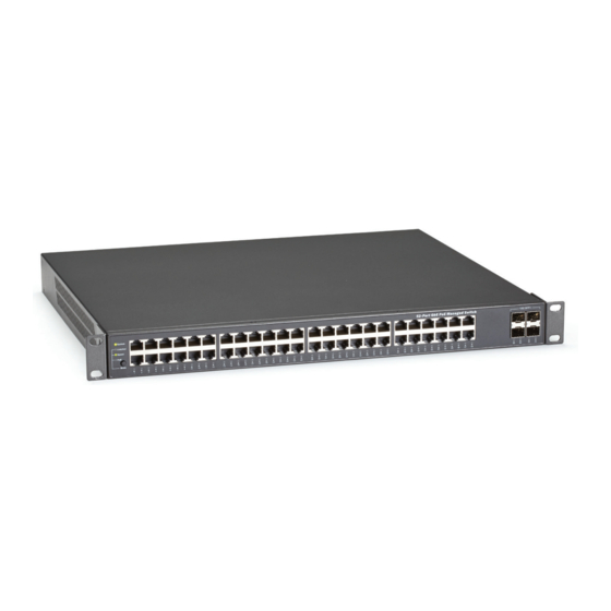
Figure 1-2. Back of the LPB5028A or LPB5052A Switch. 2.4.1 1000BASE-T Ports The LPB5028A switch has (20) 1000BASE-T RJ-45 ports and (4) copper/fiber combo ports with dual-speed SFP slots, and the LPB5052A switch has (48) 1000BASE-T RJ-45 ports. All RJ-45 ports support automatic MDI/MDI-X operation, auto-negotiation and IEEE 802.3x auto-negotiation of flow control, so the optimum data rate and transmission can be selected automatically. -
Page 14: Port And System Leds
Chapter 2: Introduction Table 2-1. Supported SFP Transceivers. Product Code Description LFP401 SFP, 155-Mbps Fiber with Extended Diagnostics, 850-nm Multimode, LC, 2 km LFP402 SFP, 155-Mbps Fiber with Extended Diagnostics, 1310-nm Multimode, 2 km, LC LFP403 SFP, 155-Mbps Fiber with Extended Diagnostics, 1310-nm Single-Mode, Plus, 30 km, LC LFP411 SFP, 1.25-Gbps Fiber with Extended Diagnostics, 850-nm Multimode, LC, 300 m LFP412... -
Page 15: Mode Status Leds
To download the Gigabit PoE+ Ethernet Managed Switch Eco user manual from the Web site: 1. Go to www.blackbox.com 2. Enter the part number (LPB5028A or LPB5052A) in the search box: 3. Click on the “Resources” tab on the product page, and select the document you wish to download. -
Page 16: Operation Of Web-Based Management
Password: blank Password After you configure the LPB5028A, you can browse to it. Type http://192.168.1.1 in the address row in a browser, and you will see the login screen prompting you for the username and password to login and access authentication. - Page 17 Chapter 3: Operation of Web-based Management Figure 3-1. The login page. NOTE: If you need to configure a function or parameter, follow the instructions in this User’s Guide. Or, you can access the Switch’s help screens in the Web User Interface (UI). 724-746-5500 | blackbox.com Page 17...
- Page 18 Chapter 3: Operation of Web-based Management Figure 3-2. Web help screen. 724-746-5500 | blackbox.com Page 18...
-
Page 19: Connecting To Pcs, Servers, Hubs, And Switches
Chapter 3: Operation of Web-based Management Connecting to Network Devices The switch is designed to connect to 10-, 100-, or 1000-Mbps network cards in PCs and servers, as well as to other switches and hubs. You can also connect it to remote devices using optional SFP transceivers. Twisted-Pair Devices Each device requires an unshielded twisted-pair (UTP) cable with RJ-45 connectors at both ends. - Page 20 Chapter 3: Operation of Web-based Management STEP 3: Label the cables to simplify future troubleshooting. See “Cable Labeling and Connection Records.” Figure 3-4. Network Wiring Connections. 724-746-5500 | blackbox.com Page 20...
-
Page 21: System
Chapter 4: System 4. System This chapter describes the basic configuration tasks, including system Information and management of the switch (Time, Account, IP, Syslog, and SNMP). 4.1 System Information After you login, the switch shows you the system information. This default page and tells you the basic system information, including “Model Name,”... -
Page 22: Configuration
Chapter 4: System • Contact: To easily manage and maintain your device, you can configure this parameter through the device’s user interface or SNMP. • Device name: The name of the switch. User-defined. • System Date: Show the system time of the switch. Its format is day of week, month, day, hours : minutes : seconds, year. •... -
Page 23: Cpu Load
Chapter 4: System Parameter description: • System Contact: The textual identification of the contact person for this managed node, together with information on how to contact this person. The allowed string length is 0 to 255, and the allowed content is the ASCII characters from 32 to 126. •... -
Page 24: Time
Figure 4-4. Time configuration screen. Parameter description: • Clock Source: Select clock source for the LPB5028A or LPB5052A. You can select “Use local Settings” or “Use NTP Server” for LPB5028A or LPB5052A time clock source. • Local Time: Show the current time of the system. -
Page 25: Ntp
Chapter 4: System • Daylight Saving: Daylight saving is adopted in some countries. If set, it will adjust the time lag or in advance in unit of hours, according to the starting date and the ending date. For example, if you set the day light saving to be 1 hour, when the time passes over the starting time, the system time will be increased one hour after one minute at the time since it passed over. -
Page 26: Account
Chapter 4: System Parameter description: • Server 1to 5: Provide the NTP IPv4 or IPv6 address of this switch. IPv6 address consists of 128-bit records represented as eight fields of up to four hexadecimal digits with a colon separating each field (:). For example, 'fe80:: 215:c5ff:fe03:4dc7’. The sym- bol '::' is a special syntax that can be used as a shorthand way of representing multiple 16-bit groups of contiguous zeros;... -
Page 27: Privilege Level
Chapter 4: System Parameter description: • User Name: The name identifying the user. This is also a link to Add/Edit User. • Password: Type the password. The allowed string length is 0 to 255, and the allowed content is the ASCII characters from 32 to 126. - Page 28 Chapter 4: System Figure 4-7. The Privilege Level configuration screen. Parameter description: • Group Name: The name identifying the privilege group. In most cases, a privilege level group consists of a single module (e.g., LACP, RSTP, or QoS), but a few of them contain more than one. The following description defines these privilege level groups in detail: System: Contact, Name, Location, Timezone, Log.
-
Page 29: Ipv4
Chapter 4: System Security: Authentication, System Access Management, Port (contains Dot1x port, MAC based and the MAC Address Limit), ACL, HTTPS, SSH, ARP, Inspection, and IP source guard. IP: Everything except “ping.” Port: Everything except “VeriPHY.” Diagnostics: “ping” and “VeriPHY.” Maintenance: System Reboot, System Restore Default, System Password, Configuration Save, Configuration Load, and Firmware Load. -
Page 30: Ipv6
Chapter 4: System Figure 4-8. The IP configuration screen. Parameter description: • DHCP Client: Enable the DHCP client by checking this box. If DHCP fails and the configured IP address is zero, DHCP will retry. If DHCP fails and the configured IP address is non-zero, DHCP will stop and the configured IP settings will be used. The DHCP cli- ent will announce the configured System Name as hostname to provide DNS lookup. -
Page 31: Syslog
Chapter 4: System Figure 4-9. The IPv6 configuration screen. Parameter description: • Auto Configuration: Enable IPv6 auto-configuration by checking this box. If it fails, the configured IPv6 address is zero. The router may delay responding to a router solicitation for a few seconds; the total time needed to complete auto-configuration can be significantly longer. -
Page 32: Log
Chapter 4: System Figure 4-10. The System Log configuration screen. Parameter description: • Server Mode: Indicates the server mode operation. When the mode operation is enabled, the syslog message will send out to syslog server. The syslog protocol is based on UDP communication and received on UDP port 514 and the syslog server will not send acknowledgments back sender since UDP is a connectionless protocol and it does not provide acknowledgments. -
Page 33: Detailed Log
Chapter 4: System Parameter description: • Auto-refresh: The device will refresh the log automatically. • Level: Level of the system log entry. The following level types are supported: Information: Information level of the system log. Warning: Warning level of the system log. Error: Error level of the system log.All: All levels. -
Page 34: Snmp
Chapter 4: System 4.6 SNMP Any Network Management System (NMS) running the Simple Network Management Protocol (SNMP) can manage the Managed devices equipped with an SNMP agent, provided that the Management Information Base (MIB) is installed correctly on the man- aged devices. -
Page 35: Configuration
Chapter 4: System 4.6.2 Configuration The function is used to configure SNMP communities. To enable new community statistics, check the button ▼, and choose <Enable> to configure the SNMP function. Web Interface To display the SNMP Configuration in the web interface: 1. -
Page 36: Users
Chapter 4: System Parameter description: • Delete: Check to delete the entry. It will be deleted during the next save. • Community: Indicates the community access string to permit access to SNMPv3 agent. The allowed string length is 1 to 32, and the allowed content is ASCII characters from 33 to 126. -
Page 37: Groups
Chapter 4: System Auth, Priv: Authentication and privacy. The value of security level cannot be modified if an entry already exists. Make sure the value is set correctly. • Authentication Protocol: Indicates the authentication protocol that this entry should belong to. Possible authentication protocols are: None: No authentication protocol. -
Page 38: Views
Chapter 4: System Parameter description: • Delete: Check to delete the entry. It will be deleted during the next save. • Security Model: Indicates the security model that this entry should belong to. Possible security models are: v1: Reserved for SNMPv1. v2c: Reserved for SNMPv2c. -
Page 39: Access
Chapter 4: System • View Name: A string identifying the view name that this entry should belong to. The allowed string length is 1 to 32, and the allowed content is ASCII characters from 33 to 126. • View Type: Indicates the view type that this entry should belong to. Possible view types are: included: An optional flag to indicate that this view subtree should be included. -
Page 40: Tarp
Chapter 4: System • Group Name: A string identifying the group name that this entry should belong to. The allowed string length is 1 to 32, and the allowed content is ASCII characters from 33 to 126. • Security Model: Indicates the security model that this entry should belong to. Possible security models are: any: Any security model accepted(v1|v2c|usm). - Page 41 Chapter 4: System Figure 4-20. The SNMP Trap Host Configuration screen. Parameters description: • Delete: Check <Delete> entry then check the <Apply> button, and entry will be deleted. • Trap Version: You may choose v1, v2c or v3 trap. • Server IP: Check to assign the SNMP Host IP address. •...
- Page 42 Chapter 4: System • Authentication Password: The length of “MD5 Authentication Password” is restricted to 8–32. The length of “SHA Authentication Password” is restricted to 8–40. • Privacy Protocol: You can set DES encryption for UserName. • Privacy Password: The length of “Privacy Password” is restricted to 8–32. 724-746-5500 | blackbox.com Page 42...
-
Page 43: Configuration
Chapter 5: Configuration 5. Configuration This chapter describes all of the basic network configuration tasks, including the Ports, Layer 2 network protocol (e.g. VLANs, QoS, IGMP, ACLs and PoE etc.) and any setting of the switch. 5.1 Port The section describes how to configure the Port detail parameters of the switch. You can enable or disable switch ports, and monitor its content or status. - Page 44 Chapter 5: Configuration Figure 5-1. The Port Configuration screen. Parameter description: • Port: This is the logical port number for this row. • Link: The current link state is displayed graphically. Green indicates the link is up and red that it is down. •...
-
Page 45: Port Description
Chapter 5: Configuration • Power Control: The Usage column shows the current percentage of the power consumption per port. The Configured column allows for changing the power savings mode parameters per port. - Disabled: All power savings mechanisms disabled. - ActiPHY: Link down power savings enabled. - PerfectReach: Link up power savings enabled. -
Page 46: Traffic Overview
Chapter 5: Configuration • Description: Description of device ports can not include “ # % & ‘ + \. • Buttons: Apply: Click to save changes. Reset: Click to undo any changes made locally and revert to previously saved values. 5.1.3 Traffic Overview The section describes to the Port statistics information and provides overview of general traffic statistics for all switch ports. -
Page 47: Detailed Statistics
Chapter 5: Configuration • Upper right icon (Refresh, Clear): Click on these icons to refresh the Port Statistics information manually. Click Clear to clean up all Port Statistics. 5.1.4 Detailed Statistics The section describes how to provide detailed traffic statistics for a specific switch port. Use the port select box to select which switch port details to display. -
Page 48: Qos Statistics
Chapter 5: Configuration Receive Total and Transmit Total • Rx and Tx Packets: The number of received and transmitted (good and bad) packets. • Rx and Tx Octets: The number of received and transmitted (good and bad) bytes. Includes FCS, but excludes framing bits. •... -
Page 49: Sfp Information
Chapter 5: Configuration Figure 5-5. The Queuing Counters Overview screen. Parameter description: • Port: The logical port for the settings contained in the same row. • Qn: Qn is the Queue number, QoS queues per port. Q0 is the lowest priority queue. •... - Page 50 Chapter 5: Configuration Figure 5-6. SFP Information Overview screen. Parameter description: • Connector Type: Display the connector type, for instance, UTP, SC, ST, LC and so on. • Fiber Type: Display the fiber mode, for instance, Multi-Mode, Single-Mode. • Tx Central Wavelength: Display the fiber optical transmitting central wavelength, for instance, 850 nm, 1310 nm, 1550 nm, and so on.
-
Page 51: Acl
5.2 ACL The LPB5028A or LPB5052A switch access control list (ACL) is probably the most commonly used object in the IOS. It is used for packet filtering but also for selecting types of traffic to be analyzed, forwarded, or influenced in some way. The ACLs are divided into EtherTypes. -
Page 52: Rate Limiters
Chapter 5: Configuration Parameter description: • Port: The logical port for the settings contained in the same row. • Policy ID: Select the policy to apply to this port. The allowed values are 1 through 8. The default value is 1. •... -
Page 53: Access Control List
Chapter 5: Configuration Figure 5-8. The ACL Rate Limiter Configuration screen. Parameter description: • Rate Limiter ID: The rate limiter ID for the settings contained in the same row. • Rate: The allowed values are: 0–3276700 in pps or 0, 100, 200, 300, ..., 1000000 in kbps. •... - Page 54 Chapter 5: Configuration This page shows the Access Control List (ACL), which is made up of the ACEs defined on this switch. Each row describes the ACE that is defined. The maximum number of ACEs is 256 on each switch. Click on the lowest plus sign to add a new ACE to the list. The reserved ACEs used for internal protocol, cannot be edited or deleted, the order sequence cannot be changed an the priority is highest.
- Page 55 Chapter 5: Configuration • Policy Filter: Specify the policy number filter for this ACE. Any: No policy filter is specified. (policy filter status is “don't-care.”) Specific: If you want to filter a specific policy with this ACE, choose this value. Two fields for entering an policy value and bit mask appears.
- Page 56 Chapter 5: Configuration • DMAC Filter: Specify the destination MAC filter for this ACE. Any: No DMAC filter is specified. (DMAC filter status is “don't-care.”) MC: Frame must be multicast. BC: Frame must be broadcast. UC: Frame must be unicast. Specific: If you want to filter a specific destination MAC address with this ACE, choose this value.
- Page 57 Chapter 5: Configuration • Sender IP Mask: When “Network” is selected for the sender IP filter, you can enter a specific sender IP mask in dotted decimal notation. • Target IP Filter: Specify the target IP filter for this specific ACE. Any: No target IP filter is specified.
- Page 58 Chapter 5: Configuration ICMP: Select ICMP to filter IPv4 ICMP protocol frames. Extra fields for defining ICMP parameters will appear. These fields are explained later in this help file. UDP: Select UDP to filter IPv4 UDP protocol frames. Extra fields for defining UDP parameters will appear. These fields are explained later in this help file.
- Page 59 Chapter 5: Configuration ICMP Parameters • ICMP Type Filter: Specify the ICMP filter for this ACE. Any: No ICMP filter is specified (ICMP filter status is “don't-care”). Specific: If you want to filter a specific ICMP filter with this ACE, you can enter a specific ICMP value. A field for entering an ICMP value appears.
-
Page 60: Acl Status
Chapter 5: Configuration • TCP SYN: Specify the TCP "Synchronize sequence numbers" (SYN) value for this ACE. 0: TCP frames where the SYN field is set must not be able to match this entry. 1: TCP frames where the SYN field is set must be able to match this entry. Any: Any value is allowed (“don't-care”). - Page 61 Chapter 5: Configuration 3. Click “Refresh” to refresh the ACL Status. Figure 5-10. ACL Rate Limiter Configuration screen. Parameter description: • User: Indicates the ACL user. • Ingress Port : Indicates the ingress port of the ACE. Possible values are: Any: The ACE will match any ingress port.
-
Page 62: Aggregation
Chapter 5: Configuration • CPU: Forward packet that matched the specific ACE to CPU. • CPU Once: Forward first packet that matched the specific ACE to CPU. • Counter: The counter indicates the number of times the ACE was hit by a frame. •... - Page 63 Chapter 5: Configuration Figure 5-11. Aggregation Mode Configuration screen. Parameter description: Hash Code Contributors • Source MAC Address: The Source MAC address can be used to calculate the destination port for the frame. Check to enable the use of the Source MAC address, or uncheck to disable. By default, Source MAC Address is enabled. •...
-
Page 64: Lacp
Chapter 5: Configuration 5.3.2 LACP Ports using Link Aggregation Control Protocol (according to IEEE 802.3ad specification) as their trunking method can choose their unique LACP GroupID to form a logic “trunked port.” The benefit of using LACP is that a port makes an agreement with its peer port before it becomes a ready member of a “trunk group”... - Page 65 Chapter 5: Configuration Parameter description: • Port: The switch port number. • LACP Enabled: Controls whether LACP is enabled on this switch port. LACP will form an aggregation when 2 or more ports are connected to the same partner. LACP can form max 12 LLAGs per switch and 2 GLAGs. •...
- Page 66 Chapter 5: Configuration Port Status This section describes that when you complete to set LACP function on the switch then it provides a Port Status overview for all LACP instances. Web Interface To display the LACP Port status in the web interface: 1.
- Page 67 Chapter 5: Configuration Parameter description: • Port: The switch port number. • LACP: “Yes” means that LACP is enabled and the port link is ”No“ means that LACP is not enabled or that the port link is down. “Backup” means that the port could not join the aggregation group but will join if other port leaves. Meanwhile its LACP status is disabled.
-
Page 68: Spanning Tree
Chapter 5: Configuration Figure 5-15. The LACP Statistics screen. Parameter description: • Port: The switch port number. • LACP Received: Shows how many LACP frames have been received at each port. • LACP Transmitted: Shows how many LACP frames have been sent from each port. •... -
Page 69: Bridge Settings
Chapter 5: Configuration STP - STP uses a distributed algorithm to select a bridging device (STP- compliant switch, bridge, or router) that serves as the root of the spanning tree network. It selects a root port on each bridging device (except for the root device) which incurs the lowest path cost when forwarding a packet from that device to the root device. - Page 70 Chapter 5: Configuration Figure 5-17. STP Bridge Configuration screen. Parameter description: Basic Settings • Protocol Version: The STP protocol version setting. Valid values are STP, RSTP, and MSTP. • Bridge Priority: Controls the bridge priority. Lower numeric values have higher priority. The bridge priority plus the MSTI instance number, concatenated with the 6-byte MAC address of the switch, forms a Bridge Identifier.
-
Page 71: Msti Mapping
Chapter 5: Configuration • Port Error Recovery Timeout: The time to pass before a port in the error-disabled state can be enabled. Valid values are between 30 and 86400 seconds (24 hours). • Buttons: Apply: Click to apply changes. Reset: Click to undo any changes made locally and revert to previously saved values. 5.4.2 MSTI Mapping You can implement a Spanning Tree protocol on the switch. -
Page 72: Msti Priorities
Chapter 5: Configuration Parameter description: Configuration Identification • Configuration Name: The name identifying the VLAN to MSTI mapping. Bridges must share the name and revision (see below), as well as the VLAN-to-MSTI mapping configuration in order to share spanning trees for MSTIs (Intra-region). The name length can be up to 32 characters. -
Page 73: Cist Ports
Chapter 5: Configuration Figure 5-19. MSTI Configuration screen. Parameter description: • MSTI: The bridge instance. The CIST is the default instance, which is always active. • Priority: Controls the bridge priority. Lower numeric values have better priority. The bridge priority plus the MSTI instance number, concatenated with the 6-byte MAC address of the switch forms a Bridge Identifier. - Page 74 Chapter 5: Configuration Figure 5-20. STP CIST Port Configuration screen. Parameter description: • Port: The switch port number of the logical STP port. • STP Enabled: Controls whether STP is enabled on this switch port. • Path Cost: Controls the path cost incurred by the port. The Auto setting will set the path cost as appropriate by the physical link speed, using the 802.1D recommended values.
-
Page 75: Msti Ports
Chapter 5: Configuration • operEdge (state flag): Operational flag describing whether the port is connecting directly to edge devices. (No Bridges attached). Transition to the forwarding state is faster for edge ports (having operEdge true) than for other ports.The value of this flag is based on AdminEdge and AutoEdge fields. - Page 76 Chapter 5: Configuration Figure 5-21. MSTI Port Configuration screen. Parameter description: • Port: The switch port number of the corresponding STP CIST (and MSTI) port. • Path Cost: Controls the path cost incurred by the port. The Auto setting will set the path cost as appropriate by the physical link speed, using the 802.1D recommended values.
-
Page 77: Bridge Status
Chapter 5: Configuration 5.4.6 Bridge Status After you complete the MSTI Port configuration, the switch can display the Bridge Status. This section provides a status overview of all STP bridge instances. The displayed table contains a row for each STP bridge instance, and the column displays the following information: Web Interface To display the STP Bridges status in the web interface:... -
Page 78: Port Statistics
Chapter 5: Configuration Figure 5-23. The STP Port status. Parameter description: • Port: The switch port number of the logical STP port. • CIST Role: The current STP port role of the CIST port. The port role can be one of the following values: AlternatePort, Backup Port, RootPort, DesignatedPort, Disabled. -
Page 79: Igmp Snooping
Chapter 5: Configuration Figure 5-24. STP Statistics screen. Parameter description: • Port: The switch port number of the logical STP port. • MSTP: The number of MSTP Configuration BPDUs received/transmitted on the port. • RSTP: The number of RSTP Configuration BPDUs received/transmitted on the port. •... - Page 80 Chapter 5: Configuration 4. Scroll to set the Throttling parameter. 5. Click Apply to save the setting. 6. To cancel the setting, click the Reset button. The switch will revert to previously saved values. Figure 5-25. IGMP Snooping Configuration screen. Figure 5-26.
-
Page 81: Vlan Configuration
Chapter 5: Configuration Parameter description: • Snooping Enabled: Enable the Global IGMP Snooping. • Unregistered IPMCv4 Flooding enabled: Enable unregistered IPMCv4 traffic flooding. • IGMP SSM Range: SSM (Source-Specific Multicast) Range allows the SSM-aware hosts and routers to run the SSM service model for the groups in the address range. -
Page 82: Port Group Filtering
Chapter 5: Configuration Parameter description: • VLAN ID: This displays the VLAN ID of the entry. • Snooping Enabled: Enable the per-VLAN IGMP Snooping. Up to 32 VLANs can be selected. • IGMP Querier: A router sends IGMP Query messages to a particular link. This Router is called the Querier. Enable the IGMP Querier in the VLAN. -
Page 83: Status
Chapter 5: Configuration 3. Scroll the Port to enable the Port Group Filtering. Specify the Filtering Groups in the blank field. 4. Click Apply to save the setting. 5. To cancel the setting, click the Reset button. The switch will revert to previously saved values. Figure 5-28. -
Page 84: Group Information
Chapter 5: Configuration Figure 5-29. The IGMP Snooping Status. Parameter description: • VLAN ID: The VLAN ID of the entry. • Querier Version: Working Querier Version currently. • Host Version: Working Host Version currently. • Querier Status: Shows the Querier status is "ACTIVE" or "IDLE". •... -
Page 85: Ipv4 Ssm Information
Chapter 5: Configuration Web Interface To display the IGMP Snooping Group Information in the web interface: 1. Click Configuration, IGMP Snooping, Group Information. 2. To auto-refresh the information, select “Auto-refresh.” 3. Click “Refresh” to refresh an entry of the IGMP Snooping Groups Information. 4. - Page 86 Chapter 5: Configuration Web Interface To display the IGMPv3 IPv4 SSM Information in the web interface: 1. Click Configuration, IGMP Snooping, IPv4 SSM Information. 2. To auto-refresh the information, select “Auto-refresh.” 3. Click “Refresh” to refresh the IGMPv3 IPv4 SSM Information. 4.
-
Page 87: Mld Snooping
Chapter 5: Configuration 5.6 MLD Snooping Curiously enough, a network node that acts as a source of IPv6 multicast traffic is only an indirect participant in MLD snooping— it just provides multicast traffic, and MLD doesn’t interact with it. NOTE: In a desktop conferencing application, a network node may act as both a source and an MLD host, but MLD interacts with that node only in its role as an MLD host. - Page 88 Chapter 5: Configuration Figure 5-33. The MLD Snooping Basic Configuration screen. Parameter description: • Snooping Enabled: Enable the Global MLD Snooping. • Unregistered IPMCv6 Flooding enabled: Enable unregistered IPMCv6 traffic flooding. NOTE: Disabling unregistered IPMCv6 traffic flooding may lead to Neighbor Discovery failure. 724-746-5500 | blackbox.com Page 88...
-
Page 89: Vlan Configuration
Chapter 5: Configuration • MLD SSM Range: SSM (Source-Specific Multicast) Range allows the SSM-aware hosts and routers run the SSM service model for the groups in the address (Using IPv6 Address) range. • Proxy Enabled: Enable MLD Proxy. This feature can be used to avoid forwarding unnecessary join and leave messages to the router side. -
Page 90: Port Group Filtering
Chapter 5: Configuration • Compatibility: Compatibility is maintained by hosts and routers taking appropriate actions depending on the versions of MLD operating on hosts and routers within a network. The allowed selection is MLD-Auto, Forced MLDv1, Forced MLDv2; the default compatibility value is MLDAuto. -
Page 91: Status
Chapter 5: Configuration Figure 5-35. The MLD Snooping Port Group Filtering Configuration screen. Parameter description: • Delete: Check to delete the entry. It will be deleted during the next save. • Port: The logical port for the settings. You can evoke to enable the port to join a filtering Group. •... - Page 92 Chapter 5: Configuration Figure 5-36. The MLD Snooping Status. Parameter description: • VLAN ID: The VLAN ID of the entry. • Querier Version: Currently working Querier Version. • Host Version: Currently working Host Version. • Querier Status: Show the Querier status is “ACTIVE” or “IDLE.” •...
-
Page 93: Group Information
Chapter 5: Configuration 5.6.5 Group Information The section describes how to set the MLD Snooping Groups Information. The “Start from VLAN” and “group” input fields allow the user to select the starting point in the MLD Group Table. Each page shows up to 99 entries from the MLD Group table (the default is 20) selected through the “entries per page” input field. -
Page 94: Mvr
Chapter 5: Configuration Each page shows up to 64 entries from the MLDv2 SSM (Source Specific Multicast) Information table (the default is 20) selected through the “entries per page” input field. When first visited, the web page will show the first 20 entries from the beginning of the MLDv2 Information Table. - Page 95 Chapter 5: Configuration 3. Click Apply to save the setting. 4. To cancel the setting, click the Reset button. It will revert to previously saved values. Figure 5-39. The MVR Configuration. Parameter description: • MVR Mode: Enable/Disable the Global MVR. •...
-
Page 96: Mvr Port Group Allow Configuration
Chapter 5: Configuration 5.7.2 MVR Port Group Allow Configuration The section describes how to add the IP Multicast Group to receive the multicast stream. Entries in the MVR port group allow table are shown on this page. The MVR Port Group Table is sorted first by port, and then by IP address. Web Interface To display the MVR Groups Information in the web interface: 1. -
Page 97: Statistics
Chapter 5: Configuration Web Interface To display the MVR Groups Information in the web interface: 1. Click Configuration, MVR, Groups Information. 2. To auto-refresh the information, click “Auto-refresh.” 3. Click the “Refresh” button to refresh a entry of the MVR Groups Information. 4. -
Page 98: Lldp
Chapter 5: Configuration Parameter description: • VLAN ID: The Multicast VLAN ID. • V1 Reports Received: The number of Received V1 Reports. • V2 Reports Received: The number of Received V2 Reports. • V3 Reports Received: The number of Received V3 Reports. •... - Page 99 Chapter 5: Configuration Figure 5-43. LLDP Configuration screen. Parameter description: LLDP Parameters • Tx Interval: The switch periodically transmits LLDP frames to its neighbors to ensure that the network discovery information is up-to-date. The interval between each LLDP frame is determined by the Tx Interval value. Valid values are restricted to 5–32768 seconds.
-
Page 100: Lldp Neighbors
Chapter 5: Configuration LLDP Port Configuration The LLDP port settings relate to the currently selected, as reflected by the page header. • Port: The switch port number of the logical LLDP port. • Mode: Select LLDP mode. Rx only: The switch will not send out LLDP information, but LLDP information from neighbor units is analyzed. Tx only: The switch will drop LLDP information received from neighbors, but will send out LLDP information. - Page 101 Chapter 5: Configuration Web Interface To show LLDP neighbors: 1. Click LLDP Neighbors. 2. Click Refresh for manual update web screen. 3. Click Auto-refresh for auto-update web screen. Figure 5-44. LLDP Neighbors information screen. NOTE: If your network without any device supports LLDP then the table will show “No LLDP neighbor information found.” Parameter description: •...
-
Page 102: Lldp-Med Configuration
Chapter 5: Configuration 5.8.3 LLDP-MED Configuration Media Endpoint Discovery is an enhancement of LLDP, known as LLDP-MED, that provides the following facilities: Auto-discovery of LAN policies (such as VLAN, Layer 2 Priority and Differentiated services (Diffserv) settings) enabling plug and play networking. - Page 103 Chapter 5: Configuration Figure 5-45. LLDP-MED Configuration screen part 1. 724-746-5500 | blackbox.com Page 103...
- Page 104 Chapter 5: Configuration Figure 5-46. LLDP-MED Configuration screen part 2. 724-746-5500 | blackbox.com Page 104...
- Page 105 Chapter 5: Configuration Parameter description: Fast start repeat count Rapid startup and Emergency Call Service Location Identification Discovery of endpoints is a critically important aspect of VoIP systems in general. In addition, it is best to advertise only those pieces of information which are specifically relevant to particular endpoint types (for example only advertise the voice network policy to permitted voice-capable devices), both in order to conserve the limited LLDPU space and to reduce security and system integrity issues that can come with inappropriate knowledge of the network policy.
- Page 106 Chapter 5: Configuration • State: National subdivisions (state, canton, region, province, prefecture). • County: County, parish, gun (Japan), district. • City: City, township, shi (Japan)—Example: Copenhagen. • City district: City division, borough, city district, ward, chou (Japan). • Block (Neighborhood): Neighbourhood, block. •...
- Page 107 Chapter 5: Configuration The network policy attributes advertised are: 1. Layer 2 VLAN ID (IEEE 802.1Q-2003) 2. Layer 2 priority value (IEEE 802.1D-2004) 3. Layer 3 Diffserv code point (DSCP) value (IETF RFC 2474) This network policy is potentially advertised and associated with multiple sets of application types supported on a given port. The application types specifically addressed are: 1.
-
Page 108: Lldp-Med Neighbors
Chapter 5: Configuration 7. Streaming Video—for use by broadcast or multicast based video content distribution and other similar applications supporting streaming video services that require specific network policy treatment. Video applications relying on TCP with buffering would not be an intended use of this application type. 8. - Page 109 Chapter 5: Configuration Figure 5-47. LLDP-MED Neighbours information screen. NOTE: If your network without any device supports LLDPMED, then the table will show ”No LLDP-MED neighbor information found.” Parameter description: • Port: The port on which the LLDP frame was received. •...
- Page 110 Chapter 5: Configuration • LLDP-MED Media Endpoint (Class II) : The LLDP-MED Media Endpoint (Class II) definition is applicable to all endpoint products that have IP media capabilities but may or may not be associated with a particular end user. Capabilities include all of the capabilities defined for the previous Generic Endpoint Class (Class I), and are extended to include aspects related to media streaming.
-
Page 111: Port Statistics
Chapter 5: Configuration 8. Video Signalling - for use in network topologies that require a separate policy for the video signalling than for the video media. • Policy: Policy indicates that an Endpoint Device wants to explicitly advertise that the policy is required by the device. Can be either Defined or Unknown. - Page 112 Chapter 5: Configuration Figure 5-48. LLDP Statistics information screen. Parameter description: Global Counters • Neighbor entries were last changed: Shows the time when the last entry was last deleted or added. It also shows the time elapsed since the last change was detected. •...
-
Page 113: Poe
Chapter 5: Configuration • Rx Frames: The number of LLDP frames received on the port. • Rx Errors: The number of received LLDP frames containing some kind of error. • Frames Discarded: If an LLDP frame is received on a port, and the switch’s internal table is full, the LLDP frame is counted and discarded. - Page 114 Chapter 5: Configuration Figure 5-49. PoE Configuration screen. Parameter description: Power Supply Configuration • Primary Power Supply [W]: The switch can have power applied by Power over Ethernet (PoE). To determine the amount of power the Powered Device (PD) may use, the amount of power the power sources can deliver must be defined. •...
-
Page 115: Status
Chapter 5: Configuration Disabled: PoE disabled for the port. Enabled: Enables PoE+ IEEE 802.3at (Class 4 PDs limited to 30W) • Priority: The Priority represents the ports priority. There are three levels of power priority named Low, High, and Critical. The priority is used in the case where the remote devices requires more power than the power supply can deliver. -
Page 116: Power Delay
Chapter 5: Configuration Parameter description: • Local Port: This is the logical port number for this row. • PD Class: To display the PD Power class that identify with a specified current. The classification current describes the amount of power the PD will require during normal operation.. •... -
Page 117: Auto Checking
Chapter 5: Configuration Figure 5-51. The POE Power Delay. Parameter description: • Port: This is the logical port number for this row. • Delay Mode: Turn on/off the power delay function. • Delay Time (0–300 sec): When rebooting, the PoE port will start to provide power to the PD when it out of delay time. •... - Page 118 Chapter 5: Configuration 4. Click Apply to apply the change. Figure 5-52. POE Auto Checking screen. Parameter description: • Ping Check: Enable Ping Check function can detects the connection between PoE port and power device. Disable will turn off the detection. •...
-
Page 119: Scheduling
Chapter 5: Configuration 5.9.5 Scheduling This page allows the user to make a perfect schedule of PoE power supply. PoE Scheduling not only makes PoE management easier but also saves more energy. Web Interface To Display Power Over Ethernet Scheduling in the web interface: 1. -
Page 120: Filtering Database
Chapter 5: Configuration 5.10 Filtering Database Filtering Data Base Configuration gathers many functions, including MAC Table Information and Static MAC Learning, which cannot be categorized to some function type. MAC table Switching of frames is based upon the DMAC address contained in the frame. The switch builds up a table that maps MAC addresses to switch ports for knowing which ports the frames should go to (based upon the DMAC address in the frame). - Page 121 Chapter 5: Configuration Figure 5-54. MAC Address Table Configuration screen. Parameter description: • Aging Configuration: By default, dynamic entries are removed from the MAC table after 300 seconds. This removal is also called aging. Configure aging time by entering a value here in seconds; for example, Age time seconds. The allowed range is 10 to 1000000 seconds.
-
Page 122: Dynamic Mac Table
Chapter 5: Configuration • Delete: Check to delete the entry. It will be deleted during the next save. • VLAN ID: The VLAN ID of the entry. • MAC Address: The MAC address of the entry. • Port Members: Checkmarks indicate which ports are members of the entry. Check or uncheck as needed to modify the entry. •... -
Page 123: Vlan
Chapter 5: Configuration Parameter description: MAC Table Columns • Type: Indicates whether the entry is a static or a dynamic entry. • VLAN: The VLAN ID of the entry. • MAC address: The MAC address of the entry. • Port Members: The ports that are members of the entry. •... - Page 124 Chapter 5: Configuration Figure 5-56. VLAN Membership Configuration screen. Parameter description: • Delete: To delete a VLAN entry, check this box. The entry will be deleted on the selected switch. If none of the ports of this switch are members of a VLAN, then the delete checkbox will be grayed out (you cannot delete that entry) during the next Save.
-
Page 125: Ports
Chapter 5: Configuration 5.11.2 Ports In the VLAN Tag Rule Setting, users can input a VID number for each port. The range of VID numbers is from 1 to 4094. Users also can choose ingress filtering rules to each port. There are two ingress filtering rules that can be applied to the switch. The Ingress Filtering Rule 1 is “forward only packets with VID matching this port’s configured VID.”... -
Page 126: Switch Status
Chapter 5: Configuration Parameter description: • Ethertype for Custom S-ports: This field specifies the ether type used for Custom S-ports. This is a global setting for all the Custom S-ports. Custom Ethertype enables the user to change the Ethertype value on a port to any value to support network devices that do not use the standard 0 x 8100 Ethertype field value on 802.1Q-tagged or 802.1p-tagged frames. - Page 127 Chapter 5: Configuration Figure 5-58. VLAN Membership Status for Combined users screen. Parameter description: VLAN USER (You can scroll to select one kind of VLAN user as described next.) VLAN User module uses services of the VLAN management functionality to configure VLAN memberships and VLAN port configurations such as PVID and UVID.
-
Page 128: Port Status
Chapter 5: Configuration 5.11.4 Port Status The Port Status function gathers the information of all VLAN status and reports it in the order of Static NAS, MVRP, MVP, Voice, VLAN, MSTP, GVRP Combined. Web Interface To Display VLAN Port Status in the web interface: 1. -
Page 129: Private Vlans
Chapter 5: Configuration • Ingress Filtering: Shows the ingress filtering on a port. This parameter affects VLAN ingress processing. If ingress filtering is enabled and the ingress port is not a member of the classified VLAN, the frame is discarded. •... - Page 130 Chapter 5: Configuration Parameter description: • Delete: To delete a private VLAN entry, check this box. The entry will be deleted during the next apply. • Private VLAN ID: Indicates the ID of this particular private VLAN. • Port Members: A row of check boxes for each port is displayed for each private VLAN ID. To include a port in a Private VLAN, check the box.
-
Page 131: Mac-Based Vlan
Chapter 5: Configuration Parameter description: • Port Members: A check box is provided for each port of a private VLAN. When checked, port isolation is enabled on that port. When unchecked, port isolation is disabled on that port. By default, port isolation is disabled on all ports. •... - Page 132 Chapter 5: Configuration Figure 5-62. MAC-based VLAN Membership Configuration screen. Parameter description: • Delete: To delete a MAC-based VLAN entry, check this box and press save. The entry will be deleted on the selected switch. • MAC Address: Indicates the MAC address. •...
-
Page 133: Protocol-Based Vlan
Chapter 5: Configuration 2. Specify the Staic NAS Combined. 3. Display MAC-based information. Figure 5-63. MAC-based VLAN Membership Status for User Static screen. Parameter description: • MAC Address: Indicates the MAC address. • VLAN ID: Indicates the VLAN ID. • Port Members: Port members of the MAC-based VLAN entry. •... - Page 134 Chapter 5: Configuration Figure 5-64. Protocol to Group Mapping Table screen. Parameter description: • Delete: To delete a Protocol to Group Name map entry, check this box. The entry will be deleted on the switch during the next Apply. • Frame Type: Frame Type can have one of the following values: 1.
- Page 135 Chapter 5: Configuration b. PID: If the OUI is hexadecimal 000000, the protocol ID is the Ethernet type (EtherType) field value for the protocol running on top of SNAP; if the OUI is an OUI for a particular organization, the protocol ID is a value assigned by that organization to the protocol running on top of SNAP.
-
Page 136: Voice Vlan
Chapter 5: Configuration Parameter description: • Delete: To delete a Group Name to VLAN map entry, check this box. The entry will be deleted on the switch during the next Apply. • Group Name: A valid Group Name is a string of atmost 16 characters which consists of a combination of alphabets (a-z or A-Z) and integers (0-9);... - Page 137 Chapter 5: Configuration Figure 5-66. Voice VLAN Configuration screen. Parameter description: • Mode: Indicates the Voice VLAN mode operation. You must disable MSTP feature before you enable Voice VLAN to avoid an ingress filtering conflict. Possible modes are: Enabled: Enable Voice VLAN mode operation. Disabled: Disable Voice VLAN mode operation.
-
Page 138: Oui
Chapter 5: Configuration • Traffic Class: Indicates the Voice VLAN traffic class. All traffic on the Voice VLAN will apply this class. • Port Mode: Indicates the Voice VLAN port mode. When the port mode isn’t disabled, you must disable the MSTP feature before you enable Voice VLAN. This will avoid the conflict of ingress filtering. -
Page 139: Garp
Chapter 5: Configuration Figure 5-67. Voice VLAN OUI Table. Parameter description: • Delete: Check to delete the entry. It will be deleted during the next save. • Telephony OUI: A telephony OUI address is a globally unique identifier assigned to a vendor by IEEE. It must be 6 characters long and the input format is "xx-xx-xx"... - Page 140 Chapter 5: Configuration Web Interface To configure GARP Port Configuration in the web interface: 1. Click GARP configures. 2. Specify GARP Configuration Parameters.. 3. Click Apply. Figure 5-68. GARP Port Configuration screen. Parameter description: • Port: The Port column shows the list of ports for which you can configure GARP settings. There are two types of configuration settings that can be configured on per port bases.
-
Page 141: Statistics
Chapter 5: Configuration - Leave Timer: The range of values for Leave Time is 600–1000 ms. The default value for Leave Timer is 600 ms. - Leave All Timer: The default value for Leave All Timer is 10000 ms • Application: Currently the only supported application is GVRP. •... -
Page 142: Gvrp
Chapter 5: Configuration Figure 5-69. The GARP Port Statistics. Parameter description: • Port: The Port coulmn displays the list of all ports for which per port GARP statistics are shown. • Peer MAC: Peer MAC is MAC address of the neighbor Switch from which a GARP frame is received. •... - Page 143 Chapter 5: Configuration Web Interface To configure GVRP Port Configuration in the web interface: 1. Click GVRP configure. 2. Specify GVRP Configuration Parameters. 3. Click Apply. Figure 5-70. GVRP Global Configuration screen. • GVRP Mode: GVRP Mode is a global setting. To enable the GVRP globally, select “Enable” from the menu and to disable GVRP globally, select ‘Disable.”...
-
Page 144: Statistics
Chapter 5: Configuration 2. GVRP rrole: This configuration is used to configure a restricted role on an interface. Disable: Select to Disable GVRP rrole on this port. Enable: Select to Enable GVRP rrole on this port. The default configuration is disable. •... -
Page 145: Qos
Chapter 5: Configuration Figure 5-71. GVRP Port Statistics screen. Parameter description: • Port: The Port coulmn shows the list of ports for which you can see port counters and statistics. • Join Tx Count: • Leave Tx Count: • Auto-refresh: Click to refresh the information automatically. •... -
Page 146: Port Classification
Chapter 5: Configuration The switch supports advanced memory control mechanisms providing excellent performance of all QoS classes under any traffic scenario, including jumbo frame. A super priority queue with dedicated memory and strict highest priority in the arbitration. The ingress super priority queue allows traffic recognized as CPU traffic to be received and queued for transmission to the CPU even when all the QoS class queues are congested. -
Page 147: Port Policing
Chapter 5: Configuration • PCP: Controls the default PCP for untagged frames. • DEI: Controls the default DEI for untagged frames. • Tag Class.: Shows the classification mode for tagged frames on this port. Disabled: Use default QoS class and DP level for tagged frames. Enabled: Use mapped versions of PCP and DEI for tagged frames. -
Page 148: Port Scheduler
Chapter 5: Configuration Figure 5-73. QoS Ingress Port Policers Configuration screen. Parameter description: • Port: The logical port for the settings contained in the same row. Click on the port number in order to configure the schedulers. • Enabled: Select the Port you need to enable the QoS Ingress Port Policers function. •... - Page 149 Chapter 5: Configuration Figure 5-74. QoS Egress Port Schedules, screen 1. 724-746-5500 | blackbox.com Page 149...
- Page 150 Chapter 5: Configuration Figure 5-75. QoS Egress Port Schedules, screen 2. Parameter description: • Port: The logical port for the settings contained in the same row. Click on the port number to configure the schedulers. • Mode: Shows the scheduling mode for this port. •...
-
Page 151: Port Shaping
Chapter 5: Configuration • Port Shaper Rate: Controls the rate for the port shaper. This value is restricted to 100–1000000 when the “Unit” is “kbps,” and it is restricted to 1–10000 when the “Unit" is "Mbps.” • Port Shaper Unit: Controls the unit of measure for the port shaper rate as “kbps” or “Mbps.” The default value is “kbps.” •... - Page 152 Chapter 5: Configuration Figure 5-76. QoS Egress Port Shapers screen 1. 724-746-5500 | blackbox.com Page 152...
- Page 153 Chapter 5: Configuration Figure 5-77. Figure 5-76. QoS Egress Port Shapers screen 2. Parameter description: • Port: The logical port for the settings contained in the same row. Click on the port number in order to configure the shapers. • Shapers (Qn): Shows “disabled” or actual queue shaper rate—e.g. “800 Mbps.” •...
-
Page 154: Port Tag Remarking
Chapter 5: Configuration • Port Shaper Rate: Controls the rate for the port shaper. The default value is ?. This value is restricted to 1–1000000 when the “Unit” is “kbps,” and it is restricted to 1-10000 when the “Unit” is “Mbps.” •... -
Page 155: Port Dscp
Chapter 5: Configuration Default: Use default PCP/DEI values. Mapped: Use mapped versions of QoS class and DP level. • Tag Remarking Mode: To scroll to select the tag remarking mode for this port. Classified: Use classified PCP/DEI values. Default: Use default PCP/DEI values. Mapped: Use mapped versions of QoS class and DP level. - Page 156 Chapter 5: Configuration Figure 5-79. QoS Port DSCP Configuration screen. Parameter description: • Port: The Port column shows the list of ports for which you can configure dscp ingress and egress settings. • Ingress: In Ingress settings, you can change ingress translation and classification settings for individual ports. There are two configuration parameters available in Ingress: 1.
-
Page 157: Dscp-Based Qos
Chapter 5: Configuration • Egress: Port Egress Rewriting can be one of the parameters below. - Disable: No Egress rewrite. - Enable: Rewrite enable without remapped. - Remap: DSCP from analyzer is remapped and frame is remarked with remapped DSCP value. •... - Page 158 Chapter 5: Configuration Figure 5-80. DSCP-Based QoS Ingress Classification Configuration screen. 724-746-5500 | blackbox.com Page 158...
-
Page 159: Dscp Translation
Chapter 5: Configuration Parameter description: • DSCP: The maximum number of supported DSCP values is 64. • Trust: Click to check if the DSCP value is trusted. • QoS Class: QoS Class value can be any value from 0–7. • DPL: Drop Precedence Level (0–3). •... - Page 160 Chapter 5: Configuration Figure 5-81. DSCP Translation Configuration screen. 724-746-5500 | blackbox.com Page 160...
-
Page 161: Dscp Classification
Chapter 5: Configuration Parameter description: • DSCP: Maximum number of supported DSCP values is 64 and valid DSCP values range from 0 to 63. • Ingress: Ingress side DSCP can be first translated to a new DSCP before using the DSCP for QoS class and DPL map. There are two configuration parameters for DSCP Translation –... -
Page 162: Qos Control List Configuration
Chapter 5: Configuration Figure 5-82. DSCP Classification Configuration screen. Parameter description: • QoS Class: Available QoS Class value ranges from 0 to 7. QoS Class (0-7) can be mapped to followed parameters. • DPL: Drop Precedence Level (0–1) can be configured for all available QoS Classes. •... - Page 163 Chapter 5: Configuration Figure 5-83. QoS Control List Configuration screen. Parameter description: • QCE#: Indicates the index of QCE. • Port: Indicates the list of ports configured with the QCE. • Frame Type: Indicates the type of frame to look for incomming frames. Possible frame types are: Any: The QCE will match all frame type.
- Page 164 Chapter 5: Configuration Multicast: Only Multicast MAC addresses are allowed. Broadcast: Only Broadcast MAC addresses are allowed. The default value is “Any.” • VID: Indicates (VLAN ID), either a specific VID or range of VIDs. VID can be in the range 1–4095 or “Any.” •...
-
Page 165: Qcl Status
Chapter 5: Configuration NOTE: All frame types are explained below: 1. Any: Allow all types of frames. 2. Ethernet: Ethernet Type Valid ethernet type can have value within 0x600–0xFFFF or “Any”; default value is “Any.” 3. LLC: SSAP Address: Valid SSAP (Source Service Access Point) can vary from 0x00 to 0xFF or “Any”; the default value is “Any.”... - Page 166 Chapter 5: Configuration Web Interface To display the QoS Control List Status in the web interface: 1. Click Configuration, QoS , QCL Status 2. If you want to auto-refresh the information then you need to select “Auto-refresh.” 3. Scroll to select the combined, static, Voice, VLAN, and conflict. 4.
-
Page 167: Storm Control
Chapter 5: Configuration 5.15.12 Storm Control The section explains how to configure the Storm control for the switch. There is a unicast storm rate control, multicast storm rate control, and a broadcast storm rate control. These only affect flooded frames, i.e. frames with a (VLAN ID, DMAC) pair not present on the MAC Address table. -
Page 168: Wred
Chapter 5: Configuration Parameter description: • Port: The port number for which the configuration below applies. • Enabled: Controls whether the storm control is enabled on this switch port. • Rate: Controls the rate for the storm control. The default value is500. This value is restricted to 100–1000000 when the “Unit” is “kbps”... -
Page 169: S-Flow Agent
Chapter 5: Configuration Parameter description: • Queue: The queue number (QoS class) for which the configuration below applies. • Enable: Enable or disable the WRED function on the switch QoS Queue. • Min. Threshold: Controls the lower RED threshold. If the average queue filling level is below this threshold, the drop probability is zero. - Page 170 Chapter 5: Configuration 2. Set the parameters. 3. Scroll to IP Type to choice with IPv4 or IPv6. 4. Click Apply to save the setting. 5. To cancel the setting, click the Reset button. It will revert to previously saved values. Figure 5-88.
-
Page 171: Sampler
Chapter 5: Configuration 5.16.2 Sampler The section explains how to set or edit the sFlow sampler. A defined sampling rate, an average of 1 out of N packets/operations, is randomly sampled. This type of sampling does not provide a 100% accurate result, but it does provide a result with quantifiable accuracy. -
Page 172: Loop Protection
Chapter 5: Configuration Parameter description: • sFlow Ports: List of the port numbers on which sFlow is configured. • sFlow Instance: Configured sFlow instance for the port number. • Sampler Type: Configured sampler type on the port and could be any of the types: None, Rx, Tx, or All. You can scroll to choice one for your sampler type. - Page 173 Chapter 5: Configuration Figure 5-90. Loop Protection Configuration screen. Parameter description: General Settings: • Enable Loop Protection: Controls whether loop protection is enabled (as a whole). • Transmission Time: The interval between each loop protection PDU sent on each port. Valid values are 1 to 10 seconds. •...
-
Page 174: Status
Chapter 5: Configuration • Enable: Controls whether loop protection is enabled on this switch port. • Action: Configures the action performed when a loop is detected on a port. Valid values are Shutdown Port, Shutdown Port and Log or Log Only. •... -
Page 175: Single Ip
Chapter 5: Configuration Parameter description: • Port: The switch port number of the logical port. • Action: The currently configured port action. • Transmit: The currently configured port transmit mode. • Loops: The number of loops detected on this port. •... -
Page 176: Information
Chapter 5: Configuration • Buttons: Apply: Click to apply changes. Reset: Click to undo any changes made locally and revert to previously saved values. 5.18.2 Information Displays the active slave switch information. Web Interface To configure the single IP parameters in the web interface: 1. - Page 177 Chapter 5: Configuration Web Interface To configure Easy Port in the web interface: 1. Click Configuration, Easy Port. 2. Set the parameters 3. Scroll to Role for what kind device you want to set on the Easy Port and connect to. 4.
-
Page 178: Mirroring
Chapter 5: Configuration 5.20 Mirroring You can mirror traffic from any source port to a target port for real-time analysis. You can then attach a logic analyzer or RMON probe to the target port and study the traffic crossing the source port in a completely unobtrusive manner. Mirror Configuration monitors the traffic on the network. - Page 179 Chapter 5: Configuration Figure 5-95. Mirror Configuration screen. Parameter description: • Port to mirror on: Port to mirror also known as the mirror port. Frames from ports that have either source (rx) or destination (tx) mirroring enabled are mirrored on this port. Disabled disables mirroring. •...
-
Page 180: Trap Event Severity
Chapter 5: Configuration Enabled: Frames received and frames transmitted are mirrored on the mirror port. NOTE: For a given port, a frame is only transmitted once. It is therefore not possible to mirror Tx frames on the mirror port. Because of this, the mode for the selected mirror port is limited to Disabled or Rx only. •... - Page 181 Chapter 5: Configuration Figure 5-96. Trap Event Severity Configuration screen. Parameter description: • Group Name: This field describes the Trap Event. • Severity Level: To scroll to select the event type with “Emerg, Alert, Crit, Error, Warming, Notice, Info and Debug.” Buttons: Apply: Click to apply changes.
-
Page 182: Smtp Configuration
Chapter 5: Configuration 5.22 SMTP Configuration The function is used to set a Alarm trap when the switch alarm then you could set the SMTP server to send you the alarm mail. Web Interface To configure the SMTP Configuration in the web interface: 1. -
Page 183: Upnp
Chapter 5: Configuration 5.23 UPnP UPnP is an acronym for Universal Plug and Play. The goals of UPnP are to allow devices to connect seamlessly and to simplify the implementation of networks in the home (data sharing, communications, and entertainment) and in corporate environments for simplified installation of computer components. -
Page 184: Security
Chapter 6: Security Chapter 6. Security This chapter describes all of the switch security configuration tasks to enhance the security of local network, including IP Source Guard, ARP Inspection, DHCP Snooping, AAA, and etc.. 6.1 IP Source Guard The section describes to configure the IP Source Guard detail parameters of the switch. You could use the IP Source Guard config- ure to enable or disable with the Port of the switch. - Page 185 Chapter 6: Security Figure 6-1. IP Source Guard Configuration mode. Parameter description: • IP Source Guard Configuration Mode: Enable the Global IP Source Guard or disable the Global IP Source Guard. All configured ACEs will be lost when the mode is enabled. •...
-
Page 186: Static Table
Chapter 6: Security • Buttons: Apply: Click to save changes. Reset: Click to undo any changes made locally and revert to previously saved values. 6.1.2 Static Table The section describes how to configure the Static IP Source Guard Table parameters of the switch. You can use the Static IP Source Guard Table to manage the entries. -
Page 187: Dynamic Table
Chapter 6: Security 6.1.3 Dynamic Table The section describes how to configure the Dynamic IP Source Guard Table parameters of the switch. You can use the Dynamic IP Source Guard Table configure to manage the entries. Web Interface To configure a Dynamic IP Source Guard Table Configuration in the web interface: 1. - Page 188 Chapter 6: Security Figure 6-4. ARP Inspection Configuration screen. Parameter description: • ARP Inspection Configuration Mode: • Enable or disable Global ARP Inspection. • Port Mode Configuration: Enable ARP Inspection on specific ports. Only when both Global Mode and Port Mode on a given port are enabled, ARP Inspection is enabled on this given port.
-
Page 189: Static Table
Chapter 6: Security 6.2.2 Static Table The section describes how to configure the Static ARP Inspection Table parameters of the switch. You can use the Static ARP Inspection Table configure to manage ARP entries. Web Interface To configure a Static ARP Inspection Table Configuration in the web interface: 1. -
Page 190: Dynamic Table
Chapter 6: Security 6.2.3 Dynamic Table The section describes to configure the Dynamic ARP Inspection Table parameters of the switch. The Dynamic ARP Inspection Table contains up to 1024 entries, and is sorted first by port, then by VLAN ID, then by MAC address, and then by IP address. Web Interface To configure a Dynamic ARP Inspection Table Configuration in the web interface: 1. - Page 191 Chapter 6: Security Figure 6-7. DHCP Snooping Configuration screen. Parameter description: • Snooping Mode: Indicates the DHCP snooping mode operation. Possible modes are: Enabled: Enable DHCP snooping mode operation. When DHCP snooping mode operation is enabled, the DHCP request messages will be forwarded to trusted ports and only allow reply packets from trusted ports. Disabled: Disable DHCP snooping mode operation.
-
Page 192: Statistics
Chapter 6: Security Buttons: Apply: Click to apply changes. Reset: Click to undo any changes made locally and revert to previously saved values. 6.3.2 Statistics The section describes how to show the DHCP Snooping Statistics information of the switch. The statistics show only packet counters when DHCP snooping mode is enabled and relay mode is disabled. -
Page 193: Dhcp Relay
Chapter 6: Security 6.4 DHCP Relay The section describes how to forward DHCP requests to another specific DHCP servers via DHCP relay. The DHCP servers may be on another network. 6.4.1 Configuration This section describes how to configure DHCP Relay setting including: Relay Mode (Enabled and Disabled) Relay Server IP setting Relay Information Mode (Enabled and Disabled) -
Page 194: Statistics
Chapter 6: Security Disabled: Disable DHCP relay information mode operation. • Relay Information Policy: Indicates the DHCP relay information option policy. When DHCP relay information mode operation is enabled, if agent receives a DHCP message that already contains relay agent information it will enforce the policy. And it only works under DHCP if relay information operation mode is enabled. -
Page 195: Nas
Chapter 6: Security • Receive from Client: The number of received packets from server. • Receive Agent Option: The number of received packets with relay agent information option. • Replace Agent Option: The number of packets that were replaced with relay agent information option. •... - Page 196 Chapter 6: Security Figure 6-11. Network Access Server Configuration screen. Figure 6-12. Port configuration screen. 724-746-5500 | blackbox.com Page 196...
- Page 197 Chapter 6: Security Parameter description: • Mode: Indicates if NAS is globally enabled or disabled on the switch. If globally disabled, all ports are allowed to forward frames. • Reauthentication Enabled: If checked, successfully authenticated supplicants/clients are reauthenticated after the interval specified by the Reauthentication Period.
- Page 198 Chapter 6: Security The “RADIUS-Assigned QoS Enabled” checkbox provides a quick way to globally enable/disable RADIUS-server assigned QoS Class functionality. When checked, the individual ports’ ditto setting determines whether RADIUS-assigned QoS Class is enabled on that port. When unchecked, RADIUS-server assigned QoS Class is disabled on all ports. •...
- Page 199 Chapter 6: Security • Port-based 802.1X: In the 802.1X-world, the user is called the supplicant, the switch is the authenticator, and the RADIUS server is the authentication server. The authenticator acts as the man-in-the-middle, forwarding requests and responses between the supplicant and the authentication server.
- Page 200 Chapter 6: Security • MAC-based Auth.: Unlike port-based 802.1X, MAC-based authentication is not a standard, but merely a best practices method adopted by the industry. In MAC-based authentication, users are called clients, and the switch acts as the supplicant on behalf of clients.
- Page 201 Chapter 6: Security - Single 802.1X For troubleshooting VLAN assignments, use the “Monitor—>VLANs—>VLAN Membership and VLAN Port” pages. These pages show which modules have (temporarily) overridden the current Port VLAN configuration. RADIUS attributes used in identifying a VLAN ID: RFC2868 and RFC3580 form the basis for the attributes used in identifying a VLAN ID in an Access-Accept packet. The following criteria are used: •...
-
Page 202: Switch Status
Chapter 6: Security Unauthorized: The port is in Force Unauthorized or a single-supplicant mode and the supplicant is not successfully authorized by the RADIUS server. X Auth/Y Unauth: The port is in a multi-supplicant mode. Currently X clients are authorized and Y are unauthorized. •... - Page 203 Chapter 6: Security Figure 6-13. Network Access Server Switch Status screen. Parameter description: • Port: The switch port number. Click to navigate to detailed NAS statistics for this port. • Admin State: The port's current administrative state. Refer to NAS Admin State for a description of possible values. •...
-
Page 204: Port Status
Chapter 6: Security 6.5.3 Port Status The section describes how to provide detailed NAS statistics for a specific switch port running EAPOL-based IEEE 802.1X authentication. Web Interface To configure a NAS Port Status Configuration in the web interface: 1. Specify Port that you want to check. 2. - Page 205 Chapter 6: Security - Single 802.1X - Multi 802.1X - MAC-based Auth. • Last Supplicant/Client Info: Information about the last supplicant/client that attempted to authenticate. This information is available for the following administrative states: - Port-based 802.1X - Single 802.1X - Multi 802.1X - MAC-based Auth.
-
Page 206: Aaa
Chapter 6: Security 6.6 AAA This section shows you how to use an AAA (Authentication, Authorization, Accounting) server to provide access control to your network. The AAA server can be a TACACS+ or RADIUS server to create and manage objects that contain settings for using AAA servers. - Page 207 Chapter 6: Security Figure 6-16. TACACS+ Accounting Configuration screen. Figure 6-17. RADIUS Configuration screen. Figure 6-18. RADIUS Accounting Configuration screen. Figure 6-19. TACACS+ Authentication Configuration. 724-746-5500 | blackbox.com Page 207...
- Page 208 Chapter 6: Security Parameter description: • Timeout: The Timeout, which can be set to a number between 3 and 3600 seconds, is the maximum time to wait for a reply from a server. If the server does not reply within this timeframe, we will consider it to be dead and continue with the next enabled server (if any).
-
Page 209: Radius Overview
Chapter 6: Security • Secret: The secret—up to 29 characters long—shared between the TACACS+ Authentication Server and the switch. • Buttons: Apply: Click to save changes. Reset: Click to undo any changes made locally and revert to previously saved values. 6.6.2 Radius Overview This section shows you an overview of the RADIUS Authentication and Accounting servers status to ensure the function is workable. -
Page 210: Radius Details
Chapter 6: Security Ready: The server is enabled, IP communication is up and running, and the RADIUS module is ready to accept accounting attempts. Dead (X seconds left): Accounting attempts were made to this server, but it did not reply within the configured timeout. The server has temporarily been disabled, but will get reenabled when the dead-time expires. - Page 211 Chapter 6: Security Web Interface To configure a System Configuration of Limit Control in the web interface: 1. Select “Enabled” in the Mode of System Configuration. 2. Check Aging Enabled. 3. Set Aging Period (Default is 3600 seconds). To configure a Port Configuration of Limit Control in the web interface: 1.
- Page 212 Chapter 6: Security • Aging Enabled: If checked, secured MAC addresses are subject to aging as discussed under Aging Period. • Aging Period: If Aging Enabled is checked, then the aging period is controlled with this input. If other modules are using the underlying port security for securing MAC addresses, they may have other requirements to the aging period.
-
Page 213: Switch Status
Chapter 6: Security Shutdown: Indicates that the port is shut down by the Limit Control module. This state can only be shown if Action is set to Shutdown or Trap & Shutdown. • Re-open Button: If a port is shutdown by this module, you may reopen it by clicking this button, which will only be enabled if this is the case. - Page 214 Chapter 6: Security Figure 6-23. Port Security Switch Status screen. Parameter description: • User Module Legend: The legend shows all user modules that may request Port Security services. • User Module Name: The full name of a module that may request Port Security services. •...
-
Page 215: Port Status
Chapter 6: Security Limit Reached: The Port Security service is enabled by at least the Limit Control user module, and that module has indicated that the limit is reached and no more MAC addresses should be taken in. Shutdown: The Port Security service is enabled by at least the Limit Control user module, and that module has indicated that the limit is exceeded. -
Page 216: Access Managment
Chapter 6: Security • Age/Hold: If at least one user module has decided to block this MAC address, it will stay in the blocked state until the hold time (measured in seconds) expires. If all user modules have decided to allow this MAC address to forward, and aging is enabled, the Port Security module will periodically check that this MAC address still forwards traffic. -
Page 217: Statistics
Chapter 6: Security Parameter description: • Mode: Indicates the access management mode operation. Possible modes are: Enabled: Enable access management mode operation. Disabled: Disable access management mode operation. • Delete: Check to delete the entry. It will be deleted during the next save. •... -
Page 218: Ssh
Chapter 6: Security • Upper right icon (Refresh, Clear): Click Refresh to refresh the Access Management Statistics information manually. Click Clear to clean up all entries. 6.9 SSH This section explains how to use SSH (Secure SHell) to securely access the Switch. SSH is a secure communication protocol that combines authentication and data encryption to provide secure encrypted communication. -
Page 219: Auth Method
Chapter 6: Security Parameter description: • Mode: Indicates the HTTPS mode operation. Possible modes are: Enabled: Enable HTTPS mode operation. Disabled: Disable HTTPS mode operation. • Automatic Redirect: Indicates the HTTPS redirect mode operation. Automatically redirect web browser to HTTPS when HTTPS mode is enabled. - Page 220 Chapter 6: Security • Buttons: Apply: Click to apply changes. Reset: Click to undo any changes made locally and revert to previously saved values. 724-746-5500 | blackbox.com Page 220...
-
Page 221: Maintenance
Chapter 7: Maintenance 7. Maintenance This chapter describes all of the switch Maintenance configuration tasks to enhance the performance of local network including Restart Device, Firmware upgrade, Save/Restore, Import/Export, and Diagnostics. 7.1 Restart Device This section describes how to restart the switch for any maintenance needs. Any configuration files or scripts that you saved in the switch should still be available afterwards. -
Page 222: Firmware Selection
Chapter 7: Maintenance Figure 7-2. Firmware update screen. Parameter description: • Browse: Click the “Browse...” button to search the Firmware URL and filename. • Upload: Click the “Upload” button and the switch will start to upload the firmware from firmware stored location PC or Server. NOTE: This page facilitates an update of the firmware controlling the switch. - Page 223 Chapter 7: Maintenance Figure 7-3. Firmware Selection screen. Parameter description: • Activate Alternate Image: Click to use the alternate image. This button may be disabled depending on system state. • Cancel: Cancel activating the backup image. Navigates away from this page. •...
-
Page 224: Save/Restore
Chapter 7: Maintenance 7.3 Save/Restore This section describes how to save and restore the Switch configuration, including reset to Factory Defaults, Save Start, Save Users, Restore Users for any maintenance needs. 7.3.1 Factory Defaults This section describes how to reset the Switch configuration to Factory Defaults. Any configuration files or scripts will revert to factory default values. -
Page 225: Save User
Chapter 7: Maintenance Parameter description: • Buttons: Save: Click the “Save” button to save current setting as Start Configuration. 7.3.3 Save User This section describes how to save users information. Any current configuration files will be saved as XML format. Web Interface To configure a Save User Configuration in the web interface: 1. -
Page 226: Export/Import
Chapter 7: Maintenance 7.4 Export/Import This section describes how to export and import the Switch configuration. Any current configuration files will be exported as XML format. 7.4.1 Export Config This section describes how to export the Switch Configuration for maintenance needs. Any current configuration files will be exported as XML format. -
Page 227: Import Config
Chapter 7: Maintenance 7.4.2 Import Config This section describes to export the Swith Configuration for maintenance needs. Any current configuration files will be exported as XML format. Web Interface To configure an Import Config Configuration in the web interface: 1. Click Browser to select the config file in your device. 2. -
Page 228: Ping
Chapter 7: Maintenance 7.5.1 Ping This section allows you to issue ICMP PING packets to troubleshoot IPv6 connectivity issues. Web Interface To configure an ICMP PING Configuration in the web interface: 1. Specify ICMP PING IP Address. 2. Specify ICMP PING Length, ping count and ping interval. 3. -
Page 229: Veriphy
Chapter 7: Maintenance 2. Specify ICMPv6 PING Length, Ping Count, Ping Interval. 3. Click Start. Figure 7-11. ICMPv6 Ping screen. Parameter description: • IP Address: The destination IP Address with IPv6. • Ping Size: The payload size of the ICMP packet. Values range from 8 bytes to 1400 bytes. •... - Page 230 Chapter 7: Maintenance Figure 7-12. VeriPHY screen. Parameter description: • Port: The port for which you are requesting VeriPHY Cable Diagnostics. • Cable Status: Port: Port number. Pair: The status of the cable pair. Length: The length (in meters) of the cable pair. 724-746-5500 | blackbox.com Page 230...
-
Page 231: Appendix A. Glossary Of Web-Based Management
Appendix A: Glossary of Web-based Management Appendix A. Glossary of Web-based Management ACE—ACE is an acronym for Access Control Entry. It describes access permission associated with a particular ACE ID. There are three ACE frame types (Ethernet Type, ARP, and IPv4) and two ACE actions (permit and deny). The ACE also contains many detailed, different parameter options that are available for individual applications. - Page 232 Appendix A: Glossary of Web-based Management ARP Inspection—ARP Inspection is a secure feature. Several types of attacks can be launched against a host or devices connected to Layer 2 networks by “poisoning” the ARP caches. This feature is used to block such attacks. Only valid ARP requests and responses can go through the switch device.
- Page 233 Appendix A: Glossary of Web-based Management DoS—DoS is an acronym for Denial of Service. In a denial-of-service (DoS) attack, an attacker attempts to prevent legitimate users from accessing information or services. By targeting at network sites or network connection, an attacker may be able to prevent network users from accessing email, web sites, online accounts (banking, etc.), or other services that rely on the affected computer.
- Page 234 Appendix A: Glossary of Web-based Management HTTPS—HTTPS is an acronym for Hypertext Transfer Protocol over Secure Socket Layer. It is used to indicate a secure HTTP connection. HTTPS provide authentication and encrypted communication and is widely used on the World Wide Web for security-sensitive communication such as payment transactions and corporate logons.
- Page 235 Appendix A: Glossary of Web-based Management LLC—The IEEE 802.2 Logical Link Control (LLC) protocol provides a link mechanism for upper layer protocols. It is the upper sub-layer of the Data Link Layer and provides multiplexing mechanisms that make it possible for several network protocols (IP, IPX) to coexist within a multipoint network.
- Page 236 Appendix A: Glossary of Web-based Management NetBIOS—NetBIOS is an acronym for Network Basic Input/Output System. It is a program that allows applications on separate computers to communicate within a Local Area Network (LAN), and it is not supported on a Wide Area Network (WAN). The NetBIOS giving each computer in the network both a NetBIOS name and an IP address corresponding to a different host name, provides the session and transport services described in the Open Systems Interconnection (OSI) model.
- Page 237 Appendix A: Glossary of Web-based Management POP3—POP3 is an acronym for Post Office Protocol version 3. It is a protocol for email clients to retrieve email messages from a mail server. POP3 is designed to delete mail on the server as soon as the user has downloaded it. However, some implementations allow users or an administrator to specify that mail be saved for some period of time.
- Page 238 Appendix A: Glossary of Web-based Management RSTP—In 1998, the IEEE with document 802.1w introduced an evolution of STP: the Rapid Spanning Tree Protocol, which provides for faster spanning tree convergence after a topology change. Standard IEEE 802.1D-2004 now incorporates RSTP and obsoletes STP, while at the same time being backwards-compatible with STP.
- Page 239 Appendix A: Glossary of Web-based Management Tag Priority—Tag Priority is a 3-bit field storing the priority level for the 802.1Q frame. TCP—TCP is an acronym for Transmission Control Protocol. It is a communications protocol that uses the Internet Protocol (IP) to exchange the messages between computers.
- Page 240 Appendix A: Glossary of Web-based Management VLAN—Virtual LAN. A method to restrict communication between switch ports. VLANs can be used for the following applications: VLAN unaware switching: This is the default configuration. All ports are VLAN unaware with Port VLAN ID 1 and members of VLAN 1.
- Page 241 NOTES 724-746-5500 | blackbox.com Page 241...
- Page 242 NOTES 724-746-5500 | blackbox.com Page 242...
- Page 243 NOTES 724-746-5500 | blackbox.com Page 243...
- Page 244 About Black Box Black Box provides an extensive range of networking and infrastructure products. You’ll find everything from cabinets and racks and power and surge protection products to media converters and Ethernet switches all supported by free, live 24/7 Tech support available in 60 seconds or less.
Need help?
Do you have a question about the LPB5028A and is the answer not in the manual?
Questions and answers