Table of Contents
Advertisement
Advertisement
Table of Contents

Subscribe to Our Youtube Channel
Related Manuals for Black Box LPB3010A


Summary of Contents for Black Box LPB3010A
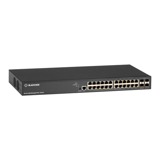
- Page 1 QUICK INSTALLATION AND CONFIG GUIDE LPB3010A, LPB3028A, LPB3052A GIGABIT MANAGED POE+ SWITCH 24/7 TECHNICAL SUPPORT AT 1.877.877.2269 OR VISIT BLACKBOX.COM 10G SFP+ System Link/AC T/Spee d Console Mode/R eset PoE + Swi tch 28- Por t GbE Man age d...
-
Page 2: Table Of Contents
NEED HELP? LEAVE THE TECH TO US LIVE 24/7 TABLE OF CONTENTS TECHNICAL SUPPORT 1.877.877.2269 1. OVERVIEW ...................................... 3 1.1 Introduction .......................................3 1.2 What’s Included ......................................3 1.3 Hardware Description ....................................4 1.3.1 Front View of the Switch ....................................4 1.3.2 Rear View of the Switch ....................................5 1.3.3 LED Descriptions ........................................ -
Page 3: Overview
Š Troubleshoot the switch Š 1.2 WHAT’S INCLUDED Your package should include the following items. If anything is missing or damaged, contact Black Box Technical Support at 877-877-2269 or info@blackbox.com Š (1) 10-, 28-, or 52-Port Gigabit Managed PoE+ Switch Š... -
Page 4: Hardware Description
NEED HELP? LEAVE THE TECH TO US LIVE 24/7 CHAPTER 1: OVERVIEW TECHNICAL SUPPORT 1.877.877.2269 1.3 HARDWARE DESCRIPTION 1.3.1 FRONT PANEL OF THE SWITCH Figure 1-1 shows the front panel of the switch. Table 1-1 describes its components. FIGURE 1-1. FRONT PANEL OF THE SWITCH NOTE: The 28-port switch is shown. -
Page 5: Rear View Of The Switch
NEED HELP? LEAVE THE TECH TO US LIVE 24/7 CHAPTER 1: OVERVIEW TECHNICAL SUPPORT 1.877.877.2269 1.3.2 BACK PANEL OF THE SWITCH Figure 1-2 shows the back panel of the switch. Table 1-2 describes its components. FIGURE 1-2. BACK PANEL SWITCH COMPONENTS TABLE 1-2. - Page 6 NEED HELP? LEAVE THE TECH TO US LIVE 24/7 CHAPTER 1: OVERVIEW TECHNICAL SUPPORT 1.877.877.2269 TABLE 1-3. SYSTEM LED INDICATOR COLOR STATE DESCRIPTION The switch is powered ON correctly. Green System The switch is not receiving power. An abnormal state, such as exceeding operating temperature range, has been detected in the switch. TABLE 1-4.
-
Page 7: Mode/Reset Button
NEED HELP? LEAVE THE TECH TO US LIVE 24/7 CHAPTER 1: OVERVIEW TECHNICAL SUPPORT 1.877.877.2269 TABLE 1-6. POE MODE LED INDICATORS COLOR STATE DESCRIPTION Green The port is enabled and supplying power to connected device. Amber An abnormal state, such as overload status, has been detected in the switch. RJ-45 Ports The port has no active network cable connected, or it is not connected to a PoE PD device. -
Page 8: Installing The Switch
NEED HELP? LEAVE THE TECH TO US LIVE 24/7 CHAPTER 2: INSTALLING THE SWITCH TECHNICAL SUPPORT 1.877.877.2269 NOTE: The switch is an indoor device. If you need to use it to connect outdoor devices such as outdoor IP cameras or outdoor Wi-Fi APs with cable, then you need to install an arrester on the cable between outdoor device and the switch. -
Page 9: Mounting The Switch On A Desk Or Shelf
NEED HELP? LEAVE THE TECH TO US LIVE 24/7 CHAPTER 2: INSTALLING THE SWITCH TECHNICAL SUPPORT 1.877.877.2269 2.2 MOUNTING THE SWITCH ON DESK OR SHELF Step 1: Verify that the workbench is sturdy and reliably grounded. Step 2: Attach the four adhesive rubber feet to the bottom of the switch. FIGURE 2-3. -
Page 10: Installing Sfp+ Modules
NEED HELP? LEAVE THE TECH TO US LIVE 24/7 CHAPTER 2: INSTALLING THE SWITCH TECHNICAL SUPPORT 1.877.877.2269 2.4 INSTALLING SFP+ MODULES You can install or remove an SFP+ module from an SFP+ port without having to power off the switch. Step 1: Insert the module into the SFP+ port. -
Page 11: Initial Configuration Of The Switch
NEED HELP? LEAVE THE TECH TO US LIVE 24/7 CHAPTER 3: INITIAL CONFIGURATION OF THE SWITCH TECHNICAL SUPPORT 1.877.877.2269 3.1 INITIAL SWITCH CONFIGURATION USING WEB BROWSERS After powering up the switch for the first time, you can perform the initial switch configuration using a web browser. For managing other switch features, refer to the Web interface user guide for details. - Page 12 NEED HELP? LEAVE THE TECH TO US LIVE 24/7 CHAPTER 3: INITIAL CONFIGURATION OF THE SWITCH TECHNICAL SUPPORT 1.877.877.2269 FIGURE 3-1. WEB INTERFACE LOGIN PAGE If you do not see the login page, perform the following steps: Š Refresh the web page. Š...
-
Page 13: Troubleshooting
NEED HELP? LEAVE THE TECH TO US LIVE 24/7 CHAPTER 4: TROUBLESHOOTING TECHNICAL SUPPORT 1.877.877.2269 The following table provides information for users to easily troubleshoot problems by taking actions based on the suggested solutions within. TABLE 4-1. TROUBLESHOOTING SYMPTOMS POSSIBLE CAUSES SUGGESTED SOLUTIONS 1. -
Page 14: Appendix A. Regulatory Information
NEED HELP? LEAVE THE TECH TO US LIVE 24/7 APPENDIX A: REGULATORY INFORMATION TECHNICAL SUPPORT 1.877.877.2269 A.1 FCC STATEMENT This equipment generates, uses, and can radiate radio-frequency energy, and if not installed and used properly, that is, in strict accordance with the manufacturer’s instructions, may cause interference to radio communication. It has been tested and found to comply with the limits for a Class A computing device in accordance with the specifications in Subpart B of Part 15 of FCC rules, which are designed to provide reasonable protection against such interference when the equipment is operated in a commercial environment. -
Page 15: Nom Statement
NEED HELP? LEAVE THE TECH TO US LIVE 24/7 APPENDIX A: REGULATORY INFORMATION TECHNICAL SUPPORT 1.877.877.2269 A.2 NOM STATEMENT 1. Todas las instrucciones de seguridad y operación deberán ser leídas antes de que el aparato eléctrico sea operado. 2. Las instrucciones de seguridad y operación deberán ser guardadas para referencia futura. 3. -
Page 16: Appendix B. Disclaimer/Trademarks
B.1 DISCLAIMER Black Box Corporation shall not be liable for damages of any kind, including, but not limited to, punitive, consequential or cost of cover damages, resulting from any errors in the product information or specifications set forth in this document and Black Box Corporation may revise this document at any time without notice. - Page 17 NEED HELP? LEAVE THE TECH TO US LIVE 24/7 NOTES TECHNICAL SUPPORT 1.877.877.2269 1.877.877.2269 BLACKBOX.COM...
- Page 18 NEED HELP? LEAVE THE TECH TO US LIVE 24/7 NOTES TECHNICAL SUPPORT 1.877.877.2269 1.877.877.2269 BLACKBOX.COM...
- Page 19 NEED HELP? LEAVE THE TECH TO US LIVE 24/7 NOTES TECHNICAL SUPPORT 1.877.877.2269 1.877.877.2269 BLACKBOX.COM...
- Page 20 NEED HELP? LEAVE THE TECH TO US LIVE 24/7 TECHNICAL SUPPORT 1.877.877.2269 © COPYRIGHT 2020. BLACK BOX CORPORATION. ALL RIGHTS RESERVED. LPB3028A_INSTALL_REV1.PDF...
Need help?
Do you have a question about the LPB3010A and is the answer not in the manual?
Questions and answers