Table of Contents
Advertisement
Quick Links
8- and 24-Port Gigabit L2 Managed PoE Switches
Meets 802.3/u/x/z Gigabit Ethernet specifications.
Includes (6) or (20) 10/100 TP ports and (2) or (4) Gigabit dual-media TP/SFP ports.
Manage the switch using:
• RS-232 serial port
• Ethernet port via CLI
• Ethernet port via Web-based SNMP
Order toll-free in the U.S.: Call 877-877-BBOX (outside U.S. call 724-746-5500) •
Customer
FREE technical support 24 hours a day, 7 days a week: Call 724-746-5500 or fax 724-746-0746 •
Support
Mailing address: Black Box Corporation, 1000 Park Drive, Lawrence, PA 15055-1018 •
Information
Web site: www.blackbox.com • E-mail: info@blackbox.com
LPB4008A
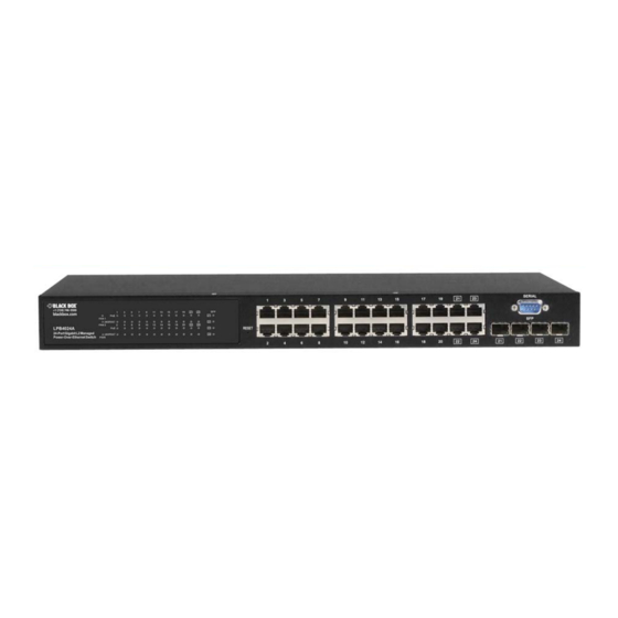
LPB4024A
Advertisement
Table of Contents

Subscribe to Our Youtube Channel
Related Manuals for Black Box LPB4008A


Summary of Contents for Black Box LPB4008A
- Page 1 Order toll-free in the U.S.: Call 877-877-BBOX (outside U.S. call 724-746-5500) • Customer FREE technical support 24 hours a day, 7 days a week: Call 724-746-5500 or fax 724-746-0746 • Support Mailing address: Black Box Corporation, 1000 Park Drive, Lawrence, PA 15055-1018 • Information Web site: www.blackbox.com • E-mail: info@blackbox.com...
- Page 2 8- and 24-Port Gigabit L2 Managed Power-over-Ethernet (PoE) Switches Circuit devices are sensitive to static electricity, which can damage their delicate electronics. Dry weather conditions or walking CAUTION: across a carpeted floor may cause you to acquire a static electrical charge. To protect your device, always: •...
- Page 3 FCC and IC RFI Statements Federal Communications Commission and Industry Canada Radio Frequency Interference Statements This equipment generates, uses, and can radiate radio-frequency energy, and if not installed and used properly, that is, in strict accordance with the manufacturer’s instructions, may cause interference to radio communication. It has been tested and found to comply with the limits for a Class A computing device in accordance with the specifications in Subpart J of Part 15 of FCC rules, which are designed to provide reasonable protection against such interference when the equipment is operated in a commercial environment.
- Page 4 8- and 24-Port Gigabit L2 Managed Power-over-Ethernet (PoE) Switches Normas Oficiales Mexicanas (NOM) Electrical Safety Statement INSTRUCCIONES DE SEGURIDAD 1. Todas las instrucciones de seguridad y operación deberán ser leídas antes de que el aparato eléctrico sea operado. 2. Las instrucciones de seguridad y operación deberán ser guardadas para referencia futura. 3.
-
Page 5: Table Of Contents
Connect To Console Port ..……………………………………………………………………………………………..20 3.4.2 Set IP Address, Subnet Mask, and Default Gateway IP Address ………………………………………………… ..20 3.4.3 Managing LPB4008A through the Ethernet Port …..………………………………………………………………… . 21 3.5 IP Address Assignment ..…………………………………………………………………………………………………… .... 22 3.5.1 IP Address ……………………………………………………………………………………………………………..22 3.5.2... - Page 6 8- and 24-Port Gigabit L2 Managed Power-over-Ethernet (PoE) Switches Table of Contents (Continued) 4.5.3 Static Forward ……………………………………………………………………………………………………… ..….56 4.5.4 MAC Alias ……………………………………………………………………………………………………………..…57 4.5.5 MAC Table …………………………………………………………………………………………………………… ..58 4.6 PoE …………………………………………………………………………………………………………………………….... 59 4.7 GVRP ………………………………………………………………………………………………………………………….... 60 4.7.1 Config …………………………………………………………………………………………………………………..60 4.7.2 Counter …………………………………………………………………………………………………………………..
- Page 7 Table of Contents Table of Contents (Continued) 4.21.3 Save User ………………………………………………………………………………………………………..….147 4.21.4 Restore User ……………………………………………………………………………………………………..….148 4.22 Export/ Import ………………………………………………………………………………………………………… .... …..148 4.23 Diagnostics …………………………………………………………………………………………………………… ..... …..149 4.23.1 Diag ………………………………………………………………………………………………………… ..………149 4.23.2 Ping …………………………………………………………………………………………………………..………150 4.24 Maintenance ………………………………………………………………………………………………………… .....……150 4.24.1 Warm Restart ………………………………………………………………………………………………..………150 4.24.2 Software Upload ……………………………………………………………………………………………...
-
Page 8: Specifications
1000 FDX WDM (BiDi) *Port 7, 8 on the LPB4008A and Ports 21-24 on the LPB4024A are TP/SFP fiber dual media ports with auto-detect function *Optional SFP module supports LC or BiDi LC transceiver. Transmission Mode: 10/100 Mbps supports full or half duplex;... -
Page 9: Management Software Specifications
FCC and IC RFI Statements 1.2 Management Software Specifications System Configuration: Supports auto-negotiation on 10/100/1000 BASE-TX ports; Web browser or console interface can set transmission speed (10-/100-/1000-Mbps) and operation mode (full-/half-duplex) on each port; enable/disable any port; set VLAN group, set trunk connection. -
Page 10: Overview
It also protects against short circuits and auto-detects power-out to the PD. This switch’s Port 7 and Port 8 (LPB4008A) or Ports 21–24 (LPB4024A) include two types of media—TP and SFP Fiber (LC, BiDi LC…). These ports support 10-/100-/1000-Mbps TP or 1000-Mbps SFP Fiber with auto-detect function. -
Page 11: What's Included
The LED display area on the left side of the panel contains a Power LED that indicates the switch’s power status. 16 port status LEDs show port status on the LPB4008A, and 48 port status LEDs show port status on the LPB4024A. One RS-232 DB9 interface can be used for configuration or management. -
Page 12: Led Indicators
8- and 24-Port Gigabit L2 Managed Power-over-Ethernet (PoE) Switches Rear Panel Figure 2-3. Rear panel: LPB4008A. Figure 2-4. Rear panel: LPB4024A. 2.5 LED Indicators Figure 2-5. LED indicators on the LPB4008A’s front panel. Figure 2-6. LED indicators on the LPB4024A’s front panel. 724-746-5500 | blackbox.com... - Page 13 2.6 Optional SFP Fiber Transceiver Modules Ports 7 and 8 on the LPB4008A include two types of media: twisted-pair (TP) and optional small form factor pluggable (SFP) fiber (LC, BiDi LC, etc.) modules. The twisted-pair ports are the switch’s two rightmost RJ-45 twisted-pair connectors. For the fiber option, 1000-Mbps fiber transceiver modules slide into the switch’s two fiber module slots (located to the right of the twisted-pair connectors on the switch’s front...
-
Page 14: Installation
Slide the module into the slot. Make sure that the module is properly seated against the slot socket/connector. Connect the fiber optic network cable to the connector(s) on the module. If you want to install a second module in the LPB4008A switch or second, third, and fourth module in the LPB4024A switch, repeat steps 1–3. -
Page 15: Power On
Chapter 3: Installation 3.1.3 Power On The switch supports a 100-240-VAC, 50-60-Hz power supply. The power supply will automatically convert the local AC power source to DC power. You can connect a device or module to the switch when it’s powered on or off. When the power is on, all port LED indicators will light up immediately and then go off. -
Page 16: Cabling Requirements
8- and 24-Port Gigabit L2 Managed Power-over-Ethernet (PoE) Switches 24-Port Gigabit L2 Managed Power-over-Ethernet Switch Figure 3-2. Installing the switch chassis in a 19" rack. 3.3 Cabling Requirements For successful installation and optimum network performance, use CAT5 or CAT5e cable. 3.3.1 Twisted-Pair Ports For a Fast Ethernet TP network connection, use CAT5 or CAT5e cable that’s up to 100 meters long. -
Page 17: Switch Cascading In Topology
Chapter 3: Installation • 62.5/125-μm multimode Gigabit fiber with multimode LC SFP module (LGB200C-MLC). • 9/125-μm single-mode Gigabit fiber with single-mode LC SFP module (LGB200C-SLC10 orLGB200C-SLC30). • 9/125-μm single-strand single-mode Gigabit fiber with BiDi LC1310-nm SFP module (LGB204C). • 9/125-μm single-strand single-mode Gigabit fiber with BiDi LC1550-nm SFP module (LGB205C). The following table lists the types of fiber that the switch supports and those not listed here are available upon request. - Page 18 8- and 24-Port Gigabit L2 Managed Power-over-Ethernet (PoE) Switches Case1: All switch ports are in the same local area network. Every port can access each other (See Figure 3-3). Figure 3-3. No VLAN Configuration Diagram. If VLAN is enabled and configured, each node in the network that can communicate with each other directly is bounded in the same VLAN area.
- Page 19 Chapter 3: Installation Case 2b: Port-based VLAN (See Figure 3-5). Figure 3-5. Port-based VLAN diagram. 1. VLAN1 members can not access VLAN2, VLAN3, and VLAN4 members. 2. VLAN2 members can not access VLAN1 and VLAN3 members, but they can access VLAN4 members. 3.
-
Page 20: Configuring The Management Agent
8- and 24-Port Gigabit L2 Managed Power-over-Ethernet (PoE) Switches 3.4 Configuring the Management Agent 3.4.1 Connect To Console Port To configure the switch via the RS-232 console port, connect the switch’s serial port directly to a DTE device, for example, a PC, through an RS-232 cable with a DB9 connector. - Page 21 LPB4008A Figure 3-8. The Login Screen for CLI. 3.4.3 Managing LPB4008A through Ethernet Port There are three ways to configure and monitor the switch through the switch’s Ethernet port. They are CLI, Web browser, and SNMP manager. The user interface for the last one is NMS dependent and is not explained in this manual. CLI and Web browser management interface are described on the next page.
-
Page 22: Ip Address Assignment
8- and 24-Port Gigabit L2 Managed Power-over-Ethernet (PoE) Switches NOTE: If the PC connects directly to the switch, you have to setup the same subnet mask between them. The subnet mask may be different for the PC at the remote site. 2. -
Page 23: Subnet Mask
Chapter 3: Installation Class C: The IP address ranges between 192.0.0.0 and 223.255.255.255. Each class C network has a 24-bit network prefix followed by an 8-bit host address. A total of 2,097,152 (221)/24 networks can be defined with a maximum of 254(28-2) hosts per network. Class D and E: Class D is a class with the first 4 MSBs (Most Significant Bits) set to 1-1-1-0 and is used for IP Multicast. -
Page 24: Default Gateway
3.6 Typical Application LPB4008A implements 8 Gigabit Ethernet TP ports with Auto MDI-X and two slots for the removable module supporting fiber connections, including LC and BiDi-LC SFP modules. LPB4024A has 20 Gigaibit Ethernet TP ports with Auto-MDIX and four slots for fiber modules. - Page 25 Chapter 3: Installation L3 Managed Switch Server L3 Managed Switch Server 8-Port Gigabit L2 Managed Power-over-Ethernet Switch 8-Port Gigabit L2 Managed Power-over-Ethernet Switch Wireless AP IP Cam Server Figure 3-13. Network Connection between Remote Site and Central Site. 724-746-5500 | blackbox.com...
- Page 26 8- and 24-Port Gigabit L2 Managed Power-over-Ethernet (PoE) Switches L2 Managed Switch 8-Port Gigabit L2 Managed Power-over-Ethernet Switch Wireless IP Cam Figure 3-14. Peer-to-peer Network Connection. L2 Managed Switch Collision Domain 1 8-Port Gigabit L2 Managed Collision Domain 2 Power-over-Ethernet Switch Wireless IP Cam Figure 3-15.
-
Page 27: Operation Of Web-Based Management
4. Operation of Web-based Management This chapter instructs you how to configure and manage the LPB4008A or LPB4024A through the web user interface it supports. Through any one port, you can access and monitor the switch status, including MIBs status, port activity, Spanning tree status, port aggregation status, multicast traffic, VLAN and priority status, even illegal access record and so on. -
Page 28: Web Management Home Overview
8- and 24-Port Gigabit L2 Managed Power-over-Ethernet (PoE) Switches Figure 4-1. Login Screen. 4.1 Web Management Overview After you login, the system information screen (Figure 4-2) appears. This page is the default and describes basic system information, including “Model Name,” “System Description,” “Location,” “Contact,” “Device Name,” “System Up Time,” “Current Time,” “BIOS Version,”... - Page 29 Chapter 4: Operation of Web-based Management Figure 4-2. The web management interface’s Home screen. 4.1.1 Screen Layout Information The top of the screen shows the front panel of the switch. The linked ports display green; ports not linked will be dark. For the optional modules, the slot will show only a cover plate if no module is installed and will show a module if a module is present.
- Page 30 8- and 24-Port Gigabit L2 Managed Power-over-Ethernet (PoE) Switches Figure 4-3. Port detail information. Figure 4-3 shows the selected port’s status, traffic status, and bandwidth rating for egress and ingress respectively. On the left-top corner is a pull-down list for Auto Logout. The auto-logout function prevents illegal users from accessing your switch as you are exiting the software. If you do not choose any selection in the Auto Logout list, the Auto Logout function turns on and the system will log out automatically after three minutes of no activity on the device.
-
Page 31: Structure Of Menu
Chapter 4: Operation of Web-based Management 4.1.2 Structure of the Menu 724-746-5500 | blackbox.com... -
Page 32: System
Contact: To easily manage and maintain this device, write down the contact person and phone here for getting help. You can configure this parameter through the device’s user interface or SNMP. Device name: The name of the switch. User-defined. Default is LPB4008A or LPB4024A. System up time: The time accumulated since this switch was powered on, formatted as day, hour, minute, second. -
Page 33: Account Configuration
Hardware-Mechanical version: The switch’s hardware and mechanical versions. The figure before the hyphen is the electronic hardware version; the one after the hyphen is the mechanical version. Serial number: The serial number assigned by Black Box. Host IP address:The switch’s IP address. -
Page 34: Time Configuration
8- and 24-Port Gigabit L2 Managed Power-over-Ethernet (PoE) Switches Figure 4-6. Account configuration screen. Edit Account: Select the account you want to edit, then click on the “Edit” button. Specify the user name and password you want. Figure 4-7. Account edit screen. Delete Account: Select the account you want to delete, then click on the “Delete”... - Page 35 Chapter 4: Operation of Web-based Management Figure 4-8. System time setting screen. Parameter description: Current Time: Shows the system’s current time. Manual: Click on the Manual button, type in the year, month, day, hour, minute, and second, then press the <Apply> button to adjust the time manually.
-
Page 36: Ip Configuration
8- and 24-Port Gigabit L2 Managed Power-over-Ethernet (PoE) Switches Mth: Range is 1–12. Default: 1 Day: Range is 1–31. Default: 1 Hour: Range is 0–23. Default: 0 Day Light Saving End: Set when to stop daylight saving time. Mth: Range is 1–12. Default: 1 Day: Range is 1–31. -
Page 37: Loop Detection
Chapter 4: Operation of Web-based Management Subnet mask: Any IP device in a network must own its IP address, which is composed of a Network address and a Host address; otherwise it can’t communicate with other devices. Subnet mask enables more network addresses. Network classes A, B, and C are too large to fit for almost all networks, so, subnet mask is introduced to solve this problem. -
Page 38: Management Policy
Parameter description: Port No: Display the port number. Valid numbers are 1–8 for LPB4008A or 1–24 for LPB4024A. Detection Port— Enable: Choose the port number and enable the port’s Loop detection. If loops are detected, the port is locked. If Loops are not detected, the port remains unlocked. - Page 39 Chapter 4: Operation of Web-based Management ----------------------------------------------------------------------- Rule 5: When both “accept and deny” lists exist, then it will deny all connections, excluding the connection within the acceptable range and NOT within the denying range at the same time. Accept Accept Deny Deny| Acc | Deny...
-
Page 40: System Log
8- and 24-Port Gigabit L2 Managed Power-over-Ethernet (PoE) Switches VID: The switch supports two kinds of options for managed valid VLAN VID, including “Any” and “Custom.” The default is “Any.” When you choose “Custom,” you can fill in the VID number. The valid VID range is 1–4094. IP Range: The switch supports two kinds of options for managed valid IP Range, including “Any”... -
Page 41: Virtual Stack
Chapter 4: Operation of Web-based Management Clear: Clear log data. 4.2.8 Virtual Stack Function name: Virtual Stack Function description: Virtual Stack Management (VSM) is the group management function. It allows you to automatically group switches that are in the same LAN. One switch will be the master device, and the others in this group will become the slave devices. VSM offers a simple centralized management function. -
Page 42: Port
8- and 24-Port Gigabit L2 Managed Power-over-Ethernet (PoE) Switches 4.3 Port Four functions, including Port Status, Port Configuration, Simple Counter, and Detail Counter are used to monitor and manage ports. Each is described in detail in the following sections. Port Configuration Configuration Status Simple Counter... -
Page 43: Port Status
Chapter 4: Operation of Web-based Management Parameter description: Speed: Set the speed and duplex of the port. For 1 Gbps fiber, the speed is always 1000 Mbps and full duplex. For twisted pair, the speed/duplex is the combination of speed mode (10/100/1000Mbps), and duplex mode (full duplex and half duplex). Media type NWay Speed... - Page 44 8- and 24-Port Gigabit L2 Managed Power-over-Ethernet (PoE) Switches Figure 4-17. Port status screen. Parameter Description: Port: Display the port number, from 1–8. Ports 7 and 8 are optional modules. Link: Show if the link on the port is active or not. If the link is connected to a device that’s working, the Link appear as “Up”; otherwise, it will be “Down.”...
- Page 45 Chapter 4: Operation of Web-based Management Figure 4-18. Port 7 detail information screen. Parameter description of Port 7–Port 8: Connector Type: Displays the connector type, for instance, UTP, SC, ST, LC and so on. Fiber Type: Displays the fiber mode, for instance, Multi-Mode, Single-Mode. Tx Central Wavelength: Displays the fiber optical transmitting central wavelength, for instance, 850-nm, 1310-nm, 1550-nm and so on.
-
Page 46: Simple Counter
8- and 24-Port Gigabit L2 Managed Power-over-Ethernet (PoE) Switches Mon3(RX PWR): Show the receiver power of the SFP module. 4.3.3 Simple Counter The function of Simple Counter collects any information and provides the counting about the traffic of the port, no matter the packet is good or bad. -
Page 47: Detail Counter
Chapter 4: Operation of Web-based Management Refresh: The simple counts will be refreshed manually when a user clicks on the “Refresh” button. Clear: The simple counts will be reset to zero when a user clicks on the “Clear” button. 4.3.4 Detail Counter The Detail Counter function counts the port traffic, whether or not the packet is good or bad. -
Page 48: Power Saving
8- and 24-Port Gigabit L2 Managed Power-over-Ethernet (PoE) Switches Tx High Priority Packets: Number of Tx packets classified as high priority. Tx Low Priority Packets: Number of Tx packets classified as low priority. Tx Broadcast: Show the number of broadcast packets transmitted. Tx Multicast: Show the number of transmitted multicast packets transmitted. -
Page 49: Vlan
Chapter 4: Operation of Web-based Management Function description: The function uses "ActiPHY Power Management" and "Perfect Reach Power Management" to save the switch’s power consumption. Figure 4-21. Power saving screen. Parameter description: Power Saving: The parameter will consider the length of any Ethernet cable connected and adjust power usage accordingly. Shorter lengths require less power. -
Page 50: Tag-Based Group
8- and 24-Port Gigabit L2 Managed Power-over-Ethernet (PoE) Switches Figure 4-22. VLAN mode. Parameter description: VLAN Mode: Port-based: Port-based VLAN is defined by port. Any packet coming in or going out from any one port of a port-based VLAN will be accepted. - Page 51 Chapter 4: Operation of Web-based Management Parameter description: VLAN Name: The name defined by administrator is associated with a VLAN group. Valid letters are A-Z, a-z, 0-9, “-“ and “_” characters. The maximum length is 15 characters. VLAN ID: VLAN identifier. Each tag-based VLAN group has a unique VID. It appears only in tag-based and Double-tag mode. IGMP-A: IGMP Aware enables the switch to issue IGMP host messages on behalf of hosts that the system discovered through standard IGMP interfaces.
-
Page 52: Port-Based Group
8- and 24-Port Gigabit L2 Managed Power-over-Ethernet (PoE) Switches Figure 4-25. Port-based VLAN memberships configuration. If you need use the PVLA (Private VLAN) function on the switch, follow the process described below: NOTE: 1. Create a VLAN as a primary VLAN, assign the VLAN ID as 2, then instruct the Private VLAN to enable Private VLAN service. 2. - Page 53 Chapter 4: Operation of Web-based Management Figure 4-28. Port-based VLAN memberships configuration. Parameter description: VLAN Name: The name defined by the administrator is associated with a VLAN group. Valid letters are A–Z, a–z, 0–9, “ - “ and “_” characters. The maximum length is 15 characters. Member Port: Enable or disable port members in the new added VLAN.
-
Page 54: Ports
8- and 24-Port Gigabit L2 Managed Power-over-Ethernet (PoE) Switches 4.4.4 Ports Function name: VLAN Port Configuration Function description: In VLAN Tag Rule Setting, users can input the VID number for each port. The VID numbers range from 1 to 4094. Users also can assign ingress filtering rules to each port. There are two ingress filtering rules that apply to the switch. The Ingress Filtering Rule 1 is “forward only packets with VID matching this port’s configured VID.”... -
Page 55: Management Vlan
Chapter 4: Operation of Web-based Management 4.4.5 Management VLAN Function name: Management VLAN Function description: Used to assign a specific VLAN for management purpose. Figure 4-32. Management VLAN screen. Parameter description: VID: Specific Management VLAN ID. 4.5 MAC MAC Table Configuration gathers many functions, including MAC Table Information, MAC Table Maintenance, Static Forward, Static Filter and MAC Alias, which cannot be categorized to a function type. -
Page 56: Static Filter
8- and 24-Port Gigabit L2 Managed Power-over-Ethernet (PoE) Switches Figure 4-33. MAC address table configuration screen. Parameter description: Aging Time: Delete a MAC address idling for a period of time from the MAC Table, which will not affect static MAC address. Range of MAC Address Aging Time is 10-1000000 seconds. -
Page 57: Static Forward
Chapter 4: Operation of Web-based Management Figure 4-34. Static filter screen. Parameter description: MAC is a six-byte long Ethernet hardware address that’s usually expressed by hex and separated by hyphens. For example, 00 – 40 - C7 - D6 – 00 – 02. VID: VLAN identifier. -
Page 58: Mac Alias
8- and 24-Port Gigabit L2 Managed Power-over-Ethernet (PoE) Switches Figure 4-35. Static forward screen. Parameter description: MAC is a six-byte long Ethernet hardware address that’s usually expressed by hex and separated by hyphens. For example, 00 – 40 - C7 - D6 – 00 – 01. Port No: The port number of the switch is 1–8. -
Page 59: Mac Table
Chapter 4: Operation of Web-based Management Figure 4-36. MAC alias screen. Parameter description: MAC Address is a six-byte long Ethernet hardware address and usually expressed by hex and separated by hyphens. For example, 00 – 40 - C7 - D6 – 00 – 01. Alias: MAC alias name you assign. -
Page 60: Poe
8- and 24-Port Gigabit L2 Managed Power-over-Ethernet (PoE) Switches Parameter description: Alias: MAC alias name you assign. MAC address: Display the MAC address of one entry you selected from the MAC entries table. Port: The port for the searched MAC Entry. VID: VLAN identifier. -
Page 61: Gvrp
Chapter 4: Operation of Web-based Management Delivering Power [W]: Displays which port supplies the PD Power and shows the power consumed by the port. Current (mA): The current supplied to the PD by the port. PD Class: The Class of the PD linked to the switch’s port. Priority: Choose from three options: Normal, Low, and High. -
Page 62: Counter
8- and 24-Port Gigabit L2 Managed Power-over-Ethernet (PoE) Switches Leave All Time: A time period to announce that all registered devices are going to be de-registered. If someone still issues a new join, then a registration will be kept in the switch. Valid range: 1000–5000 unit time, Default: 1000 unit time. Default Applicant Mode: The participent type. -
Page 63: Group
Chapter 4: Operation of Web-based Management LeaveAll Message Packets: Number of GARP BPDU with Leave All message received by the GARP application. JoinEmpty Message Packets: Number of GARP BPDU with Join Empty message received by the GARP application. JoinIn Message Packets: Number of GARP BPDU with Join In message received by the GARP application. LeaveEmpty Message Packets: Number of GARP BPDU with Leave Empty message received by the GARP application. -
Page 64: Qos Control List
8- and 24-Port Gigabit L2 Managed Power-over-Ethernet (PoE) Switches Figure 4-42. Port QoS configuration. Parameter description: Number of Classes: 1/2/4 Port: Users can choose ports (1–8) respectively with Priority Class for Per Port Priority function. Default Class: Users can set up High Priority or Low Priority for each port respectively. Low/Normal/Medium/High QCL: The number of QCL rules 1–24. - Page 65 Chapter 4: Operation of Web-based Management Figure 4-43. QoS control list configuration screen. Insert an entry Move up this entry Delete this entry Edit this entry Move up/down this entry Figure 4-44. Entry priority. QCE Configuration: The QCL searches of 12 QoS Control Entries (QCEs) from the top of the list to the bottom of the list for a match. The first matching QCE determines the frame’s QoS classification.
- Page 66 8- and 24-Port Gigabit L2 Managed Power-over-Ethernet (PoE) Switches Figure 4-46. QCE configuration screen, port range. Figure 4-47. QCE configuration screen, DSCP type. Figure 4-48. QCE configuration screen, ToS priority class. 724-746-5500 | blackbox.com...
- Page 67 Chapter 4: Operation of Web-based Management Figure 4-49. QCE configuration screen, tag priority class. Parameter description: QCL#: QCL number: 1–24 QCE Type: Ethernet Type/VLAN ID/UDP/TCP Port/DSCP/ToS/Tag Priority Ethernet Type Value: The configurable range is 0x600–0xFFFF. Well known protocols already assigned EtherType values. The commonly used values in the EtherType field and corresponding protocols are listed below: Ethertype Protocol...
-
Page 68: Rate Limiters
8- and 24-Port Gigabit L2 Managed Power-over-Ethernet (PoE) Switches 0x809B EtherTalk (AppleTalk over Ethernet) 0x80D5 IBM SNA Services over Ethernet 0x 80F3 AARP, AppleTalk Address Resolution Protocol. 0x8100 IEEE Std 802.1Q - Customer VLAN Tag Type. 0x8137 IPX, Internet Packet Exchange. 0x 814C SNMP, Simple Network Management Protocol. -
Page 69: Storm Control
Chapter 4: Operation of Web-based Management Figure 4-50. Rate limit configuration. Parameter description: Port #: Port number. Ingress Enabled: Ingress enabled to limit ingress bandwidth by policy rate. Ingress Rate: The configurable ingress rate range: 500 Kbps–1000000 kbps; 1 Mbps–1000 Mbps Ingress Unit: There are two units for ingress rate limit: kbps/Mbps Engress Enabled: Engress enabled to limit egress bandwidth by shaper rate. -
Page 70: Wizard
8- and 24-Port Gigabit L2 Managed Power-over-Ethernet (PoE) Switches Parameter description: Frame Type: There three storm frame types: Flooded unicast/Multicast/Broadcast Status: Check on square to enable. Rate (pps): Refer to the following rate configurable value list (the units are Packets Per Second [pps]): 1/2/4/8/16/32/64/128/256/512/1K/2K/4K/8K/16K/32K/64K/128K/256K/512K/1024K 4.8.5 Wizard Function name: Wizard... - Page 71 Chapter 4: Operation of Web-based Management Figure 4-53. Set up Port Policies screen. Parameter description: QCL ID: QoS Control List (QCL): 1–24 Port Member: Port Member: 1–24 724-746-5500 | blackbox.com...
- Page 72 8- and 24-Port Gigabit L2 Managed Power-over-Ethernet (PoE) Switches Figure 4-54. Set up Port Policies Finish screen. Parameter description: Wizard Again: Click on the <Wizard Again> button to go back to the QCL Configuration Wizard. Finish: When you click on <Finish>, the parameters will be set according to the wizard configuration and shown on the screen. Click on <Apply>...
- Page 73 Chapter 4: Operation of Web-based Management Figure 4-56. Set up Typical Network Application Rules. Parameter description: Audio and Video: QuickTime 4 Server/MSN Messenger Phone/Yahoo Messenger Phone/Napster/ Real Audio Games: Blizzard Battlenet (Diablo2 and StarCraft)/Fighter Ace II/Quake2/Quake3/MSN Game Zone User Definition: Ethernet Type/VLAN ID /UDP/TCP Port/DSCP Ethernet Type Value: Type Range: 0x600–0xFFFF VLAN ID: VLAN ID Range: 1–4094 UDP/TCP Port: Two Mode: Range/Specific...
- Page 74 8- and 24-Port Gigabit L2 Managed Power-over-Ethernet (PoE) Switches Figure 4-57. Set up Typical Network Application Rules. Parameter description: QCL ID: QCL ID Range: 1–24 Traffic Class: There are four classes: Low/Normal/Medium/High Figure 4-58. Set up Typical Network Application Rules Finish. 724-746-5500 | blackbox.com...
- Page 75 Chapter 4: Operation of Web-based Management Parameter description: QCL #: QoS Control List (QCL): 1–24 Figure 4-59. Set up TOS Precedence Mapping. Parameter description: QCL ID: QoS Control List (QCL): 1–24 TOS Precedence 0–7 Class: Low/Normal/Medium/High 724-746-5500 | blackbox.com...
-
Page 76: Snmp Configuration
8- and 24-Port Gigabit L2 Managed Power-over-Ethernet (PoE) Switches Figure 4-60. Set up VLAN Tag Priority Mapping. Parameter description: QCL ID: QoS Control List (QCL): 1–24 Tag Priority 0–7 Class: Low/Normal/Medium/High 4.9 SNMP Configuration Any Network Management System (NMS) running Simple Network Management Protocol (SNMP) can manage the Managed devices equipped with SNMP agent, provided that the Management Information Base (MIB) is installed correctly on the managed devices. - Page 77 Chapter 4: Operation of Web-based Management Figure 4-61 Community and trap host setting. Parameters description: SNMP: Used to activate or deactivate SNMP. The default is Enable. Get/Set/Trap Community: Community name is used as password for authenticating if the requesting network management unit belongs to the same community group.
-
Page 78: Acl
4.10 ACL The LPB4008A switch access control list (ACL) is probably the most commonly used object in the IOS. It is used for packet filtering but also for selecting types of traffic to be analyzed, forwarded, or influenced in some way. -
Page 79: Rate Limiters
Chapter 4: Operation of Web-based Management Port Copy: Disabled: Disable to copy the met ACL packets to a specific port. Port number: 1–8. Copy the met ACL packets to the selected port. Counter: The counter will increase from its initial value 0, when this port receives one of the met ACL packets, the counter value will increase +1. -
Page 80: Access Control List
8- and 24-Port Gigabit L2 Managed Power-over-Ethernet (PoE) Switches 4.10.3 Access Control List Function name: ACL Rate Limiter Configuration Function description: The switch ACL function supports up to 128 Access Control Entries (ACEs), using the shared 128 ACEs for ingress classification. You can create an ACE and assign this ACE for each port with <Any>, assign this ACE for a policy, or assign this ACE for a port. - Page 81 Chapter 4: Operation of Web-based Management Figure 4-66. Ingress Port. Figure 4-67. Access control list configuration. Parameter description: Frame Type: Any/Ethernet Type/ARP/IPv4 Any: Includes all frame types. Ethernet Type: Includes all Ethernet frame types. ARP: Includes all ARP protocol frame types. IPv4: Includes all IPv4 protocol frame types.
- Page 82 8- and 24-Port Gigabit L2 Managed Power-over-Ethernet (PoE) Switches Figure 4-68. Frame Type. Figure 4-69. SMAC filter value. Figure 4-70. Ethernet type parameters screen. 724-746-5500 | blackbox.com...
- Page 83 Chapter 4: Operation of Web-based Management Figure 4-71. ARP parameters. Figure 4-72. ARP request/reply. Figure 4-73. ARP sender IP filter. 724-746-5500 | blackbox.com...
- Page 84 8- and 24-Port Gigabit L2 Managed Power-over-Ethernet (PoE) Switches Figure 4-74. ARP target IP filter. Figure 4-75. ARP sender IP address. Figure 4-76 ARP sender IP filter. Figure 4-77. ARP target IP filter. 724-746-5500 | blackbox.com...
- Page 85 Chapter 4: Operation of Web-based Management Figure 4-78 ARP RARP DMAC match. Figure 4-79. ARP IP/Ethernet length. Figure 4-80. ARP IP. Figure 4-81. ARP Ethernet. 724-746-5500 | blackbox.com...
- Page 86 8- and 24-Port Gigabit L2 Managed Power-over-Ethernet (PoE) Switches Figure 4-82. ARP Ethernet. Figure 4-83. IPv4. 724-746-5500 | blackbox.com...
- Page 87 Chapter 4: Operation of Web-based Management Figure 4-84. IPv4 protocol filter. Figure 4-85. IPv4 ICMP parameters. Figure 4-86. IPv4 ICMP type filter. Figure 4-87 IPv4. ICMP type value. Figure 4-88. IPv4 ICMP code filter. 724-746-5500 | blackbox.com...
- Page 88 8- and 24-Port Gigabit L2 Managed Power-over-Ethernet (PoE) Switches Figure 4-89. IPv4 ICMP code value. Figure 4-90. IPv4 UDP parameters. Figure 4-91. IPv4 UDP dest. Port filter. Figure 4-92. IPv4 UDP source port filter. Figure 4-93. IPv4 UDP source port range. 724-746-5500 | blackbox.com...
- Page 89 Chapter 4: Operation of Web-based Management Figure 4-94. IPv4 UDP dest. Port filter. Figure 4-95. IPv4 UDP dest. port number. Figure 4-96. IPv4 UDP dest. port range. Figure 4-97. IPv4 TCP parameters. 724-746-5500 | blackbox.com...
- Page 90 8- and 24-Port Gigabit L2 Managed Power-over-Ethernet (PoE) Switches Figure 4-98. IPv4 TCP dest. port filter. Figure 4-99. IPv4 TCP FIN. Figure 4-100. TCP parameters. 724-746-5500 | blackbox.com...
- Page 91 Chapter 4: Operation of Web-based Management Figure 4-101. IPv4 dest. port range. Figure 4-102. IPv4 TCP FIN. Figure 4-103. IP parameters. 724-746-5500 | blackbox.com...
- Page 92 8- and 24-Port Gigabit L2 Managed Power-over-Ethernet (PoE) Switches Figure 4-104. IPv4 IP TTL. Figure 4-105. IPv4 IP Fragment. Figure 4-106. IPv4 SIP Filter. 724-746-5500 | blackbox.com...
- Page 93 Chapter 4: Operation of Web-based Management Figure 4-107. IPv4 SIP Filter, Any. Figure 4-108. IPv4 SIP Filter, Host Figure 4-109. IPv4 SIP Filter, Network. 724-746-5500 | blackbox.com...
- Page 94 8- and 24-Port Gigabit L2 Managed Power-over-Ethernet (PoE) Switches Figure 4-110. IPv4 DIP Filter. Figure 4-111. IPv4 DIP address. Figure 4-112. IPv4 DIP address. 724-746-5500 | blackbox.com...
- Page 95 Chapter 4: Operation of Web-based Management Figure 4-113. Action. Figure 4-114. Rate Limiter. 724-746-5500 | blackbox.com...
- Page 96 8- and 24-Port Gigabit L2 Managed Power-over-Ethernet (PoE) Switches Figure 4-115. Port Copy. Figure 4-116. DMAC Filter. 724-746-5500 | blackbox.com...
- Page 97 Chapter 4: Operation of Web-based Management Figure 4-117. VLAN ID Filter. Figure 4-118. VLAN ID Filter. Figure 4-119. Tag Priority. 724-746-5500 | blackbox.com...
- Page 98 8- and 24-Port Gigabit L2 Managed Power-over-Ethernet (PoE) Switches Function name: ACE Configuration Function description: The switch ACL function supports up to 128 Access Control Entries (ACEs), using the shared 128 ACEs for ingress classification. You can create an ACE and assign this ACE for each port with <Any>, assign this ACE for a policy, or assign this ACE for a port.
- Page 99 Chapter 4: Operation of Web-based Management MC: Includes all Multicast MAC addresses BC: Includes all Broadcast MAC addresses UC: Includes all Unicast MAC addresses MAC Parameters: (When Frame Type = IPv4) DMAC Filter: Any/MC/BC/UC Any: Includes all destination MAC addresses MC: Includes all Multicast MAC addresses BC: Includes all Broadcast MAC addresses UC: Includes all Unicast MAC addresses...
- Page 100 8- and 24-Port Gigabit L2 Managed Power-over-Ethernet (PoE) Switches Network: A specific IP subnet segment under the target IP mask Target IP Address: Default: 192.168.1.254 Target IP Mask: Default: 255.255.255.0 ARP SMAC Match: Any/0/1 Any: Both 0 and 1 0: The ingress ARP frames where the source MAC address does not equal SMAC under the MAC parameter settings. 1: The ingress ARP frames where the source MAC address equasl SMAC address under the MAC parameter settings.
- Page 101 Chapter 4: Operation of Web-based Management Yes: The ingress frame has fragmented packets. No: The ingress frames does not have fragmented packets IP Option: A list of optional specifications for security restrictions, route recording, and source routing. Not every datagram specifies an options field.
- Page 102 8- and 24-Port Gigabit L2 Managed Power-over-Ethernet (PoE) Switches Source Port Range.: 0–65535 Dest. Port Filter: Any/Specific/Range Any: Includes all UDP destination ports Specific: Follows Dest. Port No. setting for ingress classification Dest. Port No.: (Destination Port Number) 0–65535 Dest. Port Range.: (Destination Port Range) 0–65535 IP Parameters: (Frame Type = IPv4 and IP Protocol Filter = TCP) Source Port Filter: Any/Specific/Range Any: Includes all TCP source ports...
- Page 103 Chapter 4: Operation of Web-based Management 0: The TCP control bit PSH is 0 1: The TCP control bit PSH is 1 TCP ACK: TCP Control Bit ACK: Acknowledgment field significant. Any/0/1 Any: Includes all TCP ACK case 0: The TCP control bit ACK is 0 1: The TCP control bit ACK is 1 TCP URG: TCP Control Bit URG: Urgent Pointer field significant.
- Page 104 8- and 24-Port Gigabit L2 Managed Power-over-Ethernet (PoE) Switches Any: Includes all IP option cases Yes: The ingress frame has specific IP options. No: The ingress frame does not have specific IP options. SIP Filter: (SIP Source IP Address) Any: Includes all source IP addresses Host: Only one specific source host IP address Network: A specific IP subnet segment under the source IP mask SIP Address: Default: 192.168.1.1...
-
Page 105: Wizard
Chapter 4: Operation of Web-based Management 4.10.4 Wizard Function name: Wizard Function description: The wizard function provides four type of typical applications for user to easily configure their application with ACL function. Figure 4-120. Wizard. Parameter description: Please select an Action: Set up Policy Rules/Set up Port Policies/Set up Typical Network Application Rules/Set up Source MAC and Source IP Binding Next: Click on <Next>... - Page 106 8- and 24-Port Gigabit L2 Managed Power-over-Ethernet (PoE) Switches Figure 4-121. Set up Policy Rules. Figure 4-122. Set up Policy Rules. Figure 4-123. Set up Policy Rules. 724-746-5500 | blackbox.com...
- Page 107 Chapter 4: Operation of Web-based Management Figure 4-124. Set up Policy Rules Finish. Figure 4-125. Set up Port Policies. 724-746-5500 | blackbox.com...
- Page 108 8- and 24-Port Gigabit L2 Managed Power-over-Ethernet (PoE) Switches Figure 4-126. Set up Port Policies. Figure 4-127. Set up Port Policies finished screen. 724-746-5500 | blackbox.com...
- Page 109 Chapter 4: Operation of Web-based Management Figure 4-128. Set up Port Policies Finish Figure 4-129. Set up Typical Network Application Rules. 724-746-5500 | blackbox.com...
- Page 110 8- and 24-Port Gigabit L2 Managed Power-over-Ethernet (PoE) Switches Figure 4-130. Set up Typical Network Application Rules. Figure 4-131. Set up Typical Network Application Rules. 724-746-5500 | blackbox.com...
- Page 111 Chapter 4: Operation of Web-based Management Figure 4-132. Set up Typical Network Application Rules. Figure 4-133. Set up Typical Network Application Rules Finish. Parameter description: Common Server: DHCP/DNS/FTP/HTTP/IMAP/NFS/POP3/SAMBA/SMTP/TELNET/TFTP Instant Messaging: Google Talk/MSN Messenger/Yahoo Messenger User Definition: Ethernet Type/UDP Port/TCP Port Others: TCP Port/ICMP/Multicast IP Stream/NetBIOS/Ping Request/Ping Reply/SNMP/SNMP Traps Ingress Port: Any/Policy 1–8/Port 1–8 Action: Permit/Deny...
-
Page 112: Ip Mac Binding
8- and 24-Port Gigabit L2 Managed Power-over-Ethernet (PoE) Switches Rate Limiter ID: Disabled/1–16 4.11 IP MAC Binding The IP network layer uses a four-byte address. The Ethernet link layer uses a six-byte MAC address. Binding these two address types together allows the transmission of data between the layers. The primary purpose of IP-MAC binding is to restrict the access to a switch to a number of authorized users. -
Page 113: Configuration
Chapter 4: Operation of Web-based Management Port No: 1–8 VID: VLAN ID: 1–4094 Add: Input MAC, IP, Port and VID, then click on <Add> to create a new entry into the IP MAC Binding table Figure 135. IP MAC binding dynamic entry. Delete: Select one of entry from the table, then click on <Delete>... -
Page 114: Server
8- and 24-Port Gigabit L2 Managed Power-over-Ethernet (PoE) Switches server using EAP encapsulation. Before successfully authenticating, the supplicant can only connect to the authenticator to perform authentication message exchange or access the network from the uncontrolled port. Authenticator’s System Supplicant’ Authentication Server’s System Services Offered... - Page 115 Chapter 4: Operation of Web-based Management 4. If the authenticator doesn’t send EAP-Request/Identity, the supplicant will initiate EAPOL-Start the process by sending it to the authenticator. 5. The Supplicant replies with an EAP-Response/Identity to the authenticator. The authenticator will embed the user ID into Radius- Access-Request command and send it to the authentication server to confirm its identity.
- Page 116 8- and 24-Port Gigabit L2 Managed Power-over-Ethernet (PoE) Switches MultiHost 802.1X is the only type of authentication supported in the switch. In this mode, once a supplicant is authorized, the devices connected to this port can access the network resources. The 802.1X Port-based Network Access Control function supported by the switch is somewhat complex,.
-
Page 117: Port Configuration
Chapter 4: Operation of Web-based Management Secret Key: The secret key between authentication server and authenticator. It is a string of 1–31 characters. The character string may contain upper case, lower case, and 0-9 and is case-sensitive. Do not enter blank spaces between two characters. The default secret key is Radius. -
Page 118: Status
8- and 24-Port Gigabit L2 Managed Power-over-Ethernet (PoE) Switches Advanced: Each client attached to this port must do 802.1X authentication individually. Clientless: The clients don’t need to install the 802.1X client function. The client PC (for example WINDOW XP) does not need to enable 802.1X client function to do 802.1X authentication. -
Page 119: Statistics
Chapter 4: Operation of Web-based Management Port: Port number: 1–8 Mode: Show this port’s IEEE 802.1X operating mode: There are four modes: Disable, Normal, Advance, and Clientless. Status: Show this port’s IEEE 802.1X security current status: Authorized or Unauthorized 4.12.4 Statistics Function name: 802.1X Port Statistics Port1 Function description: Show the IEEE 802.1X authentication related counters to monitor authenticator status. -
Page 120: Trunking Configuration
8- and 24-Port Gigabit L2 Managed Power-over-Ethernet (PoE) Switches Port: Port Number: 1–8 Auto- refresh: Refresh the authenticator counters in the web UI automatically. Refresh: Click on <Refresh> to update the authenticator counters in the web UI. Clear: Click on <Clear> to clear all authenticator counters in the web UI. 4.13 Trunking Configuration Use the Port Trunking Configuration to configure the Link Aggregation settings. -
Page 121: Aggregator View
Chapter 4: Operation of Web-based Management Figure 4-143. Trunk port setting/status screen. Parameter description: Port: Port Number: 1–8 Method: This determines the method a port uses to aggregate with other ports. None: When set to none, the port will not aggregate with any other port. LACP: A port uses LACP as its trunk method to aggregate with other ports also using LACP. -
Page 122: Aggregation Mode Configuration
8- and 24-Port Gigabit L2 Managed Power-over-Ethernet (PoE) Switches Figure 4-144. Aggregator view screen. Parameter description: Aggregator: Shows the aggregator ID (from 1 to 8) of every port. Every port is also an aggregator, and its own aggregator ID is the same as its own Port No. -
Page 123: Lacp System Priority
Chapter 4: Operation of Web-based Management 4.13.4 LACP System Priority Function name: LACP System Priority Function description: Sets the priority part of the LACP system ID. LACP will only aggregate together the ports whose peer link partners are all on a single system. Each system supports LACP that will be assigned a globally unique System Identifier for this purpose. -
Page 124: Configuration
8- and 24-Port Gigabit L2 Managed Power-over-Ethernet (PoE) Switches Parameter description: STP State: Show the current STP Enabled / Disabled status. Default is “Disabled.” Bridge ID: Show the switch’s bridge ID (it stands for the switch’s MAC address.) Bridge Priority: Show this switch’s current bridge priority setting. Default is 32768. Designated Root: Show root bridge ID of this network segment. -
Page 125: Stp Port Configuration
Bridge Priority: The lower the bridge priority is, the higher priority it has. Usually, the bridge with the highest bridge priority is the root. If you want to have the LPB4008A as root bridge, you can set this value lower than that of bridge in the LAN. The valid value is 0–... - Page 126 8- and 24-Port Gigabit L2 Managed Power-over-Ethernet (PoE) Switches Figure 4-149. STP port configuration. Parameter description: Port Status displays the current state of a port. We cannot manually set it because it displays the status only. There are three possible states (according to the 802.1w specification): DISCARDING state indicates that this port can neither forward packets nor contribute learning knowledge.
-
Page 127: Mstp
Chapter 4: Operation of Web-based Management There are three parameters, Auto, True, and False, used to configure the type of the point-to-point link. If you configure this parameter to be Auto, it means RSTP will use the duplex mode resulting from the auto-negotiation. In today’s switched networks, most links are running in full-duplex mode. -
Page 128: Instance View
8- and 24-Port Gigabit L2 Managed Power-over-Ethernet (PoE) Switches Parameter description: Region Name: 0-32 characters (A variable length text string encoded within a fixed field of 32 octets, that conforms to RFC 2271’s definition of SnmpAdminString.) Revision Level: 0-65535 4.15.3 Instance View Function name: MSTP Instance Config Function description: Provides an MST instance table that includes information (an MSTI’s VLAN membership) of all spanning instances provisioned in the particular MST region that the bridge belongs to. - Page 129 Chapter 4: Operation of Web-based Management Instance Status: (Figure 4-156) Show the status report of a particular spanning tree instance. Port Status: (Figure 4-157) Show the status report of all ports regarding a specific spanning tree instance. Figure 4-153. Edit MSTI / Vlan Parameter description: Vlan Mapping: VID STRING VID STRING Example: 2.5-7.100-200.301.303.1000-1500 (Valid VID Range: 1–4094)
- Page 130 8- and 24-Port Gigabit L2 Managed Power-over-Ethernet (PoE) Switches Max Hops is used to specify the initial value of the Remaining Hops for Regional Root Bridge (Either CIST Regional Root or MSTI Regional Root). Figure 4-155. Port Config. Parameter description: Port: 1–8 Path Cost: 1–...
- Page 131 Chapter 4: Operation of Web-based Management Restricted TCN: Yes/No “Yes” causes the Port not to propagate received topology change notifications and topology changes to other Ports. This parameter is “No” by default. If set it can cause temporary loss of connectivity after changes in a spanning tree’s active topology as a result of persistent incorrectly learned station location information.
- Page 132 8- and 24-Port Gigabit L2 Managed Power-over-Ethernet (PoE) Switches Force Version: Shows the current spanning tree protocol version configured. Bridge Max Age: Shows the bridge’s Max Age setting. Bridge Forward Delay: Shows the bridge’s Forward Delay setting. Bridge Max Hops: Shows the bridge’s Max Hops setting. Instance Priority: Spanning tree priority value for a specific tree instance (CIST or MSTI).
-
Page 133: Mirror
Chapter 4: Operation of Web-based Management Status: The port’s role in the spanning tree topology. Possible values are “dsbl”(disable port), ”alt”(alternate port) , “bkup”(backup port), “ROOT”(root port), “DSGN”(designated port), and “MSTR”(master port). The last 3 are possible port roles for a port to transition to FORWARDING state. -
Page 134: Multicast
8- and 24-Port Gigabit L2 Managed Power-over-Ethernet (PoE) Switches 4.17 Multicast This function establishes which multicast groups forward the multicast packet to the member ports. This avoids wasting the bandwidth while IP multicast packets are running over the network. This is because a switch that does not support IGMP or IGMP Snooping cannot tell the multicast packet from the broadcast packet, so it can only treat them all as broadcast packets. -
Page 135: Igmp Snooping
Chapter 4: Operation of Web-based Management Figure 4-160. IGMP Proxy. Parameter description: IGMP Proxy Enable: This function supports IGMP Proxy Enable on the Switch. Enable: Choose ”IGMP Proxy Enable” to enable IGMP Proxy on Switch. Default: Disable Unregister IPMC Flooding Enable: Set unregister to prevent the traffic from appearing in the multicast table for flooding. General Query Interval: Set the switch’s general sending query period time. -
Page 136: Igmp Group Membership
8- and 24-Port Gigabit L2 Managed Power-over-Ethernet (PoE) Switches Figure 4-161 IGMP Snooping Parameter description: Host Time Out: Set IGMP Snooping enable and the Host packet received by Switch timeout period. The units are seconds and time range is from 1 to 65535. The default is 125 seconds. Fast Leave: Set which port will enable the Fast leave mode in IGMP snooping mode. -
Page 137: Mvr
Chapter 4: Operation of Web-based Management Refresh: Update the multicast group membership. 4.17.5 MVR Function name: MVR configuration (Multicast VLAN Registration) Function description: Multicast VLAN Registration (MVR) routes packets received in a multicast source VLAN to one or more receive VLANs. Clients are in the receive VLANs and the multicast server is in the source VLAN. -
Page 138: Group Allow
8- and 24-Port Gigabit L2 Managed Power-over-Ethernet (PoE) Switches Figure 4-164. MVID configuration. Figure 4-165. MVID configuration. Parameter description: Add new MVID: Creates a new MVID entry. MVID: Sets the MVR Group ID. Member Port: Sets which port will join the MVR Group member. Router Port: Sets which port will become the MVR Group router port. -
Page 139: Mvr Group Membership
Chapter 4: Operation of Web-based Management Figure 4-166. MVID Group Allow configuration. Parameter description: IP Address Range: The switch supports two kinds of options for managed valid IP range, including “Any” and “Custom.” The default is “Any.” If you chose Custom,” you can assign an effective IP range. The valid range is 224.0.0.0–239.255.255.255. MVID: The switch supports two kinds of options for managed valid MVID, including “Any”... -
Page 140: Alarm Configuration
8- and 24-Port Gigabit L2 Managed Power-over-Ethernet (PoE) Switches 4.18 Alarm Configuration Alarm Configuration Events Configuration Email Configuration Figure 4-168. Alarm configuration menu tree. 4.18.1 Events Function name: Events Configuration Function description: The Trap Events Configuration function is used to enable the switch to send out the trap information while pre- defined trap events occur. -
Page 141: Email
Chapter 4: Operation of Web-based Management STP: STP Topology Changed, STP Disabled, STP Enabled LACP: LACP Disabled, LACP Enabled, LACP Member Added, LACP Port Failure GVRP: GVRP Disabled, GVRP Enabled VLAN: VLAN Disabled, Port-based VLAN Enabled, Tag-based VLAN Enabled, Metro-mode Vlan Enabled, Double-tag Vlan Enabled Module Swap: Module Inserted, Module Removed, Dual Media Swapped 4.18.2 Email Function name: Email Configuration... -
Page 142: Dhcp Snooping
8- and 24-Port Gigabit L2 Managed Power-over-Ethernet (PoE) Switches 4.19 DHCP Snooping DHCP Snooping DHCP Snooping State DHCP Snooping Entry DHCP Snooping Client DHCP snooping menu tree. 4.19.1 DHCP Snooping State Function name: DHCP Snooping State Function description: The addresses assigned to DHCP clients on unsecure ports can be carefully controlled using the dynamic bindings registered with DHCP Snooping. - Page 143 Chapter 4: Operation of Web-based Management Figure 4-171. DHCP Snooping State. Parameter description: VID: When DHCP snooping is enabled on the specified VLAN, DHCP packet filtering will be performed on any un-trusted ports within the VLAN. It sets an available VLAN ID to enable the DHCP snooping on VLAN interface. Trust Port 1: If DHCP snooping is enabled globally, and also enabled on the VLAN where the DHCP packet is received, all DHCP packets are forwarded for a trusted port.
-
Page 144: Lldp
8- and 24-Port Gigabit L2 Managed Power-over-Ethernet (PoE) Switches Figure 4-172. DHCP Snooping Client. Parameter description: MAC: Shows the DHCP snooping client’s MAC address. VID: Shows the DHCP snooping client’s VLAN ID. Port: Shows the DHCP snooping client’s port. IP: Shows the DHCP snooping client’s IP address. Lease: Shows the DHCP snooping client’s lease. - Page 145 Chapter 4: Operation of Web-based Management Figure 4-173. LLDP parameter. Parameter: Tx Interval: Changes the interval between consecutive transmissions of LLDP advertisements on any given port. (Default: 30 seconds) Tx Hold: Specifies the amount of time the receiving device holds a Link Layer Discovery Protocol (LLDP) packet before discarding it. (Default: 4 times) Tx Delay: Specifies the delay between successive LLDP frame transmissions initiated by value/status changes in the LLDP local system’s MIB.
-
Page 146: Lldp Entry
8- and 24-Port Gigabit L2 Managed Power-over-Ethernet (PoE) Switches 4.20.2 LLDP Entry Function name: LLDP Entry Function description: The LLDP Entry function allows a switch to display which ports build the LLDP available entry. Use this information to track LLDP packets back to a physical port and enable or disable the LLD P. -
Page 147: Save/Restore
Chapter 4: Operation of Web-based Management Figure 4-175. LLDP statistics. Parameter description: Neighbor entries were last changed at: The time period since neighbor entries were changed. Total Neighbors Entries Added: The total neighbors’ entries added are received. Total Neighbors Entries Deleted: The total neighbors’ entries deleted are received. Total Neighbors Entries Dropped: The total neighbors’... -
Page 148: Factory Defaults
8- and 24-Port Gigabit L2 Managed Power-over-Ethernet (PoE) Switches Working Configuration: The configuration you are currently using. This can be changed at any time. The configurations you are using are saved into this configuration file. This is updated each time you press the <Apply> button. User Configuration: The configuration file for the specified or backup purposes. -
Page 149: Restore User
Chapter 4: Operation of Web-based Management Function description: Save the current configuration as a user configuration file in flash memory. Figure 4-178. Save the current setting as user configuration prompt. Restore User 4.21.4 Function name: Restore User Configuration Function description: The Restore User Configuration function can retrieve the previous confirmed working configuration stored in the flash memory to update start configuration. -
Page 150: Diagnostics
8- and 24-Port Gigabit L2 Managed Power-over-Ethernet (PoE) Switches Figure 4-180. Export/Import configuration file. Parameter description: Export File Path: Export Start: Export Save As Start’s config file stored in the flash. Export User-Conf: Export Save As User’s config file stored in the flash. Import File Path: Import Start: Import Save As Start’s config file stored in the flash. -
Page 151: Ping
Chapter 4: Operation of Web-based Management Figure 4-181. Diagnostics screen. 4.23.2 Ping Function name: Ping Test Function description: Ping Test function detects if the target device is alive or not through ICMP protocol with report messages. The switch provides Ping Test function to let you know if the target device is available or not. -
Page 152: Software Upload
Software Upload Function name: Click on <Browse> to select a specific LPB4008A firmware file from the Web management PC, then click Function description: on <Upload> to confirm the firmware upgrade. The new firmware will be uploaded into the switch and write to flash memory. -
Page 153: Operation Of Cli Management
Chapter 5: Operation of CLI Management 5. Operation of CLI Management 5.1 CLI Management Refer to Chapter 3 for basic installation. The following briefly describes the network connection. - Locate the correct DB9 null modem cable with female DB9 connector. Null modem cable comes with the management switch. Refer to Chapter 8 for null modem cable configuration. -
Page 154: Global Commands Of Cli
Description: Back to the top mode. When you enter this command, your current position would move to the top mode. If you use this command in the top mode, you are still in the position of the top mode. Argument: None. Possible value: None. Example: LPB4008A# alarm LPB4008A(alarm)# events LPB4008A(alarm-events)# end LPB4008A# 724-746-5500 | blackbox.com... - Page 155 Description: Back to the previous mode. When you enter this command, your current position will move back to the previous mode. If you use this command in the top mode, you remain in top mode. Argument: None. Possible value: None. Example: LPB4008A# trunk LPB4008A(trunk)# exit LPB4008A# Help Syntax: help Description: Show available commands.
-
Page 156: Restore Default
Argument: [#]: show last number of history records. (optional) Possible value: [#]: 1, 2, 3, …., 256 Example: LPB4008A(ip)# history Command history: 0. trunk 1. exit 2. LPB4008A# trunk 3. LPB4008A(trunk)# exit 4. LPB4008A# 5. ? 6. trunk 7. exit 8. alarm 9. - Page 157 Chapter 5: Operation of CLI Management LPB4008A# restore default Restoring ... Restore Default Configuration Successfully Press any key to reboot system. restore user Syntax: restore user Description: Restore the startup configuration as a user defined configuration. If restoring default successfully, the CLI prompts if you need to reboot immediately or not.
-
Page 158: Local Commands Of Cli
<value>: max-times , range 1–10 Possible value: <port range> : 1 to 8 <value>: 1-10, default is 2 Example: LPB4008A(802.1X)# set maxReq 2 2 set mode Syntax: set mode <port-range> <mode> Description: Set up the 802.1X authentication mode of each port. - Page 159 Possible value: <port range>: 1 to 8 <authorized>: 0, 1 or 2 Example: LPB4008A(802.1X)# set port-control 2 2 set quietPeriod Syntax: set quietPeriod <port-range> <value> Description: A timer used by the Authenticator state machine to define periods of time during when it will not attempt to acquire a Supplicant.
- Page 160 Possible value: <port range>: 1 to 8 <value>: 1-10, default is 2 Example: LPB4008A(802.1X)# set reAuthMax 2 2 set reAuthPeriod Syntax: set reAuthPeriod <port-range> <value> Description: A constant that defines a nonzero number of seconds between periodic reauthentication of the supplicant.
- Page 161 <secret-key>: set up the value of secret-key, and the length of secret-key is from 1 to 31 Possible value: <udp-port >: 1~65535, default is 1812 Example: LPB4008A(802.1X)# set auth-server 192.168.1.115 1812 WinRadius set suppTimeout Syntax: set suppTimeout <port-range> <value> Description: A timer used by the Backend Authentication state machine in order to determine timeout conditions in the exchanges between the Authenticator and the Supplicant or Authentication Server.
-
Page 162: Show Statistics
Description: Displays the parameter settings of each port. Argument: <port range> : syntax 1,5-7, available from 1 to 8 Possible value: <port range> : 1 to 8 Example: LPB4008A(802.1X)# show port-config 1, 2 port 1) Mode : Disabled port control : Auto... - Page 163 Chapter 5: Operation of CLI Management Argument: None Possible value: None Example: LPB4008A(802.1X)# show server Authentication Server ________________________________________ IP Address : 192.168.1.1 UDP Port : 1812 Secret Key : Radius Accounting Server _________________________________________ IP Address: 192.168.1.1 UDP Port : 1812 Secret Key : Radius B.
- Page 164 8- and 24-Port Gigabit L2 Managed Power-over-Ethernet (PoE) Switches Possible value: None. Example: LPB4008A(account)# modify aaaaa username/password: the length is from 5 to 15. Current username (aaaaa):bbbbb New password: Confirm password: Username changed successfully. Password changed successfully. Show Syntax: show Description: Shows system account, including account name and identity.
- Page 165 <rate_limiter>: 0-16 (0: disable) <port copy>: 0-8 (0:disable) Possible value: <port>: 1-8 <permit/deny>: 0-1 <rate_limiter>: 0-16 <port copy>: 0-8 Example: LPB4008A(acl)# action 5 0 2 2 LPB4008A(acl)# show port policy id action rate limiter port copy counter a class map …….
- Page 166 Syntax: move <index1> <index2> Description: Move the ACE (Access Control Entry) configuration between index1 and index2.. Argument: None. Possible value: None. Example: LPB4008A(account)# move 1 2 Policy Syntax: policy <policy> <ports> Description: Set acl port policy on the switch Argument: <policy>: 1-8 <ports>: 1-24...
- Page 167 Possible value: <id>: 1-16 <rate>: 1, 2, 4, 8, 16, 32, 64, 128, 256, 512, 1000, 2000, 4000, 8000, 16000, 32000, 64000, 128000, 256000, 512000, 1024000 Example: LPB4008A(acl)# ratelimiter 3 16000 LPB4008A(acl)# Syntax: set [<index>] [<next index>] [switch | (port <port>) | (policy <policy>)] [<vid>] [<tag_prio>] [<dmac_type>]...
- Page 168 Description: Remove the E-mail address configuration. Argument: <#>: email address number, range: 1 to 6 Possible value: <#>: 1 to 6 Example: LPB4008A(alarm-email)# del mail-address 2 del server-user Syntax: del server-user Description: To remove the server configuration, user account, and password.
-
Page 169: Set User
Argument: <#>: email address number, range: 1 to 6 <mail address>: email address Possible value: <#>: 1 to 6 Example: LPB4008A(alarm-email)# set mail-address 1 abc@mail.abc.com set server Syntax: set server <ip> Description: Set up the IP address of the email server. - Page 170 Description: Disable email and trap events trap. Argument: <range>: del the range of events, syntax 1, 5-7 Possible value: <range>: 1~24 Example: LPB4008A(alarm-events)# del all 1-3 del email Syntax: del email <range> Description: Disable the events email. Argument: <range>: del the range of email, syntax 1, 5-7 Possible value: <range>: 1~24...
-
Page 171: Set Trap
Chapter 5: Operation of CLI Management Example: LPB4008A(alarm-events)# set all 1-3 set email Syntax: set email <range> Description: Enable the events email. Argument: <range>: set the range of email, syntax 1, 5-7 Possible value: <range>: 1~24 Example: LPB4008A(alarm-events)# set email 1-3 set trap Syntax: set trap <range>... - Page 172 (alarm) Syntax: show Description: Show alarm displays the configuration of Events, or E-mail. Argument: None. Possible value: None. Example: LPB4008A(alarm)# show events LPB4008A(alarm)# show email E. autologout Autologout Syntax: autologout <time> Description: Set up the autologout timer. Argument: <time>: range 1 to 3600 seconds, 0 for autologout off, current setting is 180 seconds.
- Page 173 Chapter 5: Operation of CLI Management < ip address> the TFTP server ip address Possible value: none Example: LPB4008A(config-file)# export current 192.168.1.63 Export successful. import Syntax: import <current | user> < ip address> Description: Run the port start function. Argument: None...
- Page 174 Argument: <vid>: enter which gvrp group you created, using value vid. Available range: 1 to 4094 <port>: 1 to 8 < 0 | 1>: Possible value: <vid>: 1~4094 <port>: 1 to 8 Example: LPB4008A(gvrp)# group applicant 2 5 0 GVRP group information Current Dynamic Group Number: 1 VID Member Port ---- -------------------------------------------------- set applicant Syntax: set applicant <port>...
- Page 175 <LeaveAllTime>: leaveall timer, available from 1000 to 5000. Leave Time must equal double Join Time at least. Possible value: <port>: 1 to 8 <JoinTime>: 20 to 100 <LeaveTime>: 60 to 300 <LeaveAllTime>: 1000 to 5000 Example: LPB4008A(gvrp)# set timer 2-8 25 80 2000 724-746-5500 | blackbox.com...
- Page 176 Syntax: group grpinfo <vid> Description: Show the gvrp group. Argument: <vid>: Set the vlan id from 1 to 4094. Possible value: <vid>: 1 to 4094 Example: LPB4008A(gvrp)# group grpinfo 2 GVRP group information VID Member Port ---- ------------------------------------------------- 724-746-5500 | blackbox.com...
- Page 177 Description: Set router ports to disable. Argument: <port >: syntax 1, 5-7, available from 1 to 8 Possible value: <port >: 1 to 8 Example: LPB4008A(igmp)# set drp 1-10 set erp Syntax: set erp <port> Description: Set router ports to enable.
-
Page 178: Enable Dhcp
8- and 24-Port Gigabit L2 Managed Power-over-Ethernet (PoE) Switches Possible value: <state>: 0 or 1 Example: LPB4008A(igmp)# set flood 1 show gm Syntax: show gm Description: Display group membership. Argument: None. Possible value: None. Example: LPB4008A(igmp)# show gm show igmpp Syntax: show igmpp Description: Display igmp proxy setting. - Page 179 Possible value: <ip>: 192.168.1.2 or others <mask>: 255.255.255.0 or others <gateway>: 192.168.1.253 or others Example: LPB4008A(ip)# set ip 192.168.1.2 255.255.255.0 192.168.1.253 Show Syntax: show Description: Display the system’s DHCP function state, IP address, subnet mask, default gateway, DNS mode, DNS server IP address, and current IP address.
- Page 180 <ip>: ip address <port>: 1 to 8 <vid>: 1 to 4094 Example: LPB4008A(ip_mac_binding)# set entry 1 00-11-2f-de-7b-a9 192.168.2.2 1 1 delete ip Syntax: delete ip < 0 | 1> <ip> Description: Delete ip mac binding entry by ip. Argument: <0 | 1>: 0: client, 1: server <ip>: ip address...
- Page 181 Description: Disable the loop detection function for the switch ports. Argument: <#>: set up the range of the ports to search for, syntax 1, 5-7, available form 1 to 8. Possible value: <#>: 1 to 8 Example: LPB4008A(loop-detection)# disable 1-8 LPB4008A(loop-detection)# show Detection Port Locked Port...
- Page 182 Description: Resume locked ports on switch. Argument: <#>: set up the range of the ports to search for, syntax 1,5-7, available form 1 to 8 Possible value: <#>: 1 to 8 Example: LPB4008A (loop-detection)# resume 1-8 LPB4008A (loop-detection)# show Detection Port Locked Port...
- Page 183 Syntax: del <mac> Description: Delete mac alias entry. Argument: <mac>: set up the MAC format: xx-xx-xx-xx-xx-xx Possible value: <mac>: set up the MAC format: xx-xx-xx-xx-xx-xx Example: LPB4008A(mac-alias)# set 23-56-r5-55-3f-03 test3 LPB4008A(mac-alias)# show MAC Alias Alias =========================================== 23-56-00-55-3F-03 test3...
- Page 184 8- and 24-Port Gigabit L2 Managed Power-over-Ethernet (PoE) Switches LPB4008A(mac-alias)# show MAC Alias Alias =========================================== 23-56-00-55-3F-03 test3 23-56-00-55-EF-03 test13 23-56-00-55-EF-33 test1 show Syntax: show Description: Display MAC alias entry. Argument: None Possible value: none Example: LPB4008A(mac-alias)# show MAC Alias Alias...
- Page 185 Description: Set MAC table age out time of the dynamic learning MAC. Argument: <#>: age-timer in seconds, 0, 10, 1000000. The value zero disables aging. Possible value: <#>: 0, 10 to 1000000. Example: LPB4008A(mac-table-maintain)# set age-time 300 LPB4008A(mac-maintenance)# show E api_ai 26/vtss_ Aging Configuration:...
- Page 186 8- and 24-Port Gigabit L2 Managed Power-over-Ethernet (PoE) Switches Example: LPB4008A(mac-table-maintain)# set learning 1-24 auto LPB4008A(mac-maintenance)# show E api_ai 26/vtss_ Aging Configuration: Enter into sta Age time: 300mode MAC Table Learning Port Learning Mode-<< Global commands > Auto Auto Auto...
-
Page 187: Show Filter
Possible value: <mac>: mac address <port>: 0-8 <vid>: 0, 1-4094 [alias]: mac alias name Example: LPB4008A(mac-static-mac)# add 00-02-03-04-05-06 3 0 aaa LPB4008A(mac-static-mac)# Syntax: del <mac> <vid> Description: Delete the static MAC entry. Argument: <mac>: mac address, format: 00-02-03-04-05-06 <vid>: vlan id. 0, 1-4094. VID must be zero if vlan mode is not tag-based Possible value: <mac>: mac address... -
Page 188: Show Forward
1 to 8: available port number 0: disable mirror function Possible value: <#>: 1 to 8 Example: LPB4008A(mirror)# set mirror 2 set monitor-destination Syntax: set monitor-destination <range> Description: Set monitor destination port. The packets sent by this port will be copied to the monitoring port. - Page 189 Argument: <range>: the monitoring port that is chosen for the mirror function. Only one port can be configured, available from 1 to 8. Possible value: <range>:1 to 8 Example: LPB4008A(mirror)# set monitor-source 8 LPB4008A(mirror)# show Port to mirror to: 1...
-
Page 190: Set Config
1,5-7, available from 1 to 8 Possible value: Usage: migrate-check <port range> port range syntax: 1,5-7, available from 1 to 8 Example: LPB4008A (mstp)# migrate-check 1-2 set config Syntax: set config <Max Age><Forward Delay><Max Hops> Description: Set max age,forward delay,max hops. - Page 191 Chapter 5: Operation of CLI Management <Max Hops>: available from 6 to 40. Recommended value is 20. Example: LPB4008A(mstp)# set config 20 15 20 LPB4008A(mstp)# set msti-vlan Syntax: set msti-vlan <instance-id><vid-string> Description: Map Vlan ID(s) to an MSTI Argument: <instance-id>: MSTI id available from 1 to 4095 <vid-string>: syntax example: 2.5-7.100-200...
- Page 192 8- and 24-Port Gigabit L2 Managed Power-over-Ethernet (PoE) Switches <admin edge>: 0->non-edge port,1->edge ports Example: LPB4008A(mstp)# set p-edge 10-12 0 LPB4008A(mstp)# set p-hello Syntax: set p-hello <port range> <hello time> Description: Set per port hello time Argument: <port range>: syntax: 1, 5-7, available from 1 to 8 <hello time>: only 1~2 are valid values...
- Page 193 Description: Set per port restricted role. Argument: <port range> syntax: 1, 5-7, available from 1 to 8 <restricted role>: 0->false, 1->True Possible value: <port range>: 1 to 8 <restricted role>: 0->false, 1->True Example: LPB4008A(mstp)# set r-role 1-4 1 724-746-5500 | blackbox.com...
- Page 194 8- and 24-Port Gigabit L2 Managed Power-over-Ethernet (PoE) Switches LPB4008A(mstp)# set r-role 5-8 0 LPB4008A(mstp)# show ports 0 ==== =========== ====== ========= ===== ===== ==Operational== =Restricted= Port Port Status Role Path Cost Hello Edge-Port Role ==== =========== ====== ========= ===== ===== ========= ===== ====== =====...
- Page 195 LPB4008A(mstp)# set revision-level Syntax: set rev <revision-level> Description: Set mstp revision-level (0–65535) Argument: <revision-level>: 0~65535 Possible value: <revision-level>: 0~65535 Example: LPB4008A(mstp)# set revision-level 30000 LPB4008A(mstp)# show region-info Name: test2 Revision: 30000 Instances: 0 LPB4008A(mstp)# set version Syntax: set version <stp|rstp|mstp>...
-
Page 196: Show Ports
TOPOLOGY CHANGE COUNT(SECs) : 0 LPB4008A(mstp)# show pconf Syntax: show pconf <instance-id> Description: Show port configuration. Argument: instance-id: 0->CIST; 1-4095->MSTI Possible value: <instance-id>: 0->CIST; 1-4095->MSTI Example: LPB4008A(mstp)# show pconf 0 set r-role true auto false false true auto false true true auto false true... - Page 197 Chapter 5: Operation of CLI Management Syntax: show ports <instance-id> Description: Show port status. Argument: instance-id: 0->CIST; 1-4095->MSTI Possible value: <instance-id>:0->CIST; 1-4095->MSTI Example: LPB4008A(mstp)# show ports 0 show region-info Syntax: show region-info Description: Show region config. Argument: none Possible value: none...
- Page 198 Description: Delete a management policy entry. Argument: <index>: a specific or range management policy entry(s) e.g. delete 2,3,4-7 Possible value: <index>: a specific or range management policy entry(s) Example: LPB4008A(policy)# add name rule2 ip 192.168.4.23-192.168.4.33 port 6-8 type s,t action d LPB4008A(policy)# show 1) Name...
-
Page 199: Clear Counter
Description: Clear all ports’ counter (include simple and detail port counter) information. Argument: None Possible value: None Example: LPB4008A (port)# clear counter set description Syntax: set description <port-range> <description> Description: Set port description. Argument: <port range> syntax: 1, 5-7, available from 1 to 8 <description>: set port description, max 47 characters... - Page 200 8- and 24-Port Gigabit L2 Managed Power-over-Ethernet (PoE) Switches Example: LPB4008A(port)# set description 3-8 salesdepartment LPB4008A(port)# show config Speed/ Flow Maximum Excessive Synopsis: add name George ip 192.168.1.1- Port Duplex Control Frame Collision Description type Auto Disabled 9600 Discard Auto...
- Page 201 Argument: <port range> syntax: 1, 5-7, available from 1 to 8 <value>: Allowed value are 1518-9600 bytes. Possible value: <port range> syntax: 1 to 8 <value>: 1518-9600 bytes. Example: LPB4008A(port)# set max-frame 3-6 1518 LPB4008A(port)# show config Speed/ Flow Maximum Excessive commands...
-
Page 202: Show Config
8- and 24-Port Gigabit L2 Managed Power-over-Ethernet (PoE) Switches Example: LPB4008A (port)# set speed 3 auto LPB4008A (port)# show status Speed/ Port Link Duplex Rx Pause Tx Pause Description ---- ---- --------- -------- -------- -------------------------------- 1 Up 100M/Full Disabled Disabled... - Page 203 Description: Display the SFP module information. Argument: <port>: SFP port of the switch, available from 7, 8 Possible value: <port>: 7- 8 Example: LPB4008A(port)# show sfp 7 Port 7 SFP information --------------------------------------------------------------------- Connector Type : SFP - Unknown or unspecified...
-
Page 204: Set Port
8- and 24-Port Gigabit L2 Managed Power-over-Ethernet (PoE) Switches Argument: None. Possible value: None. Example: LPB4008A (port)# show simple-counter set max-frame Set per-port maximum frame size LPB4008A(port)# show status Syntax: show status Description: Display the port’s current status. Argument: None. - Page 205 <queuing mode>: strict | weighted <low queue weighted>: 1/2/4/8 <normal queue weighted>: 1/2/4/8 <medium queue weighted>: 1/2/4/8 <high queue weighted>: 1/2/4/8 Example: LPB4008A(qos-ports)# set port 2 medium 1 3 weithted 2 2 2 2 LPB4008A(qos-ports)# show 2 Medium 1 Weighted Fair 2/2/2/2 3 Low...
- Page 206 <tos>: tos priority , available from 1 to 8 <tagpriority>: tag priority, available from 1 to 8 <qce type>: Ethernet <value>: 0xfff0 <class>: high Example: LPB4008A(qos-qcl)# set 2 0 3 ethernet 0xfff0 high LPB4008A(qos-qcl)# show 2 1 QCE Type: Ethernet Type Ethernet Type Value:0xfff0 Traffic Class:...
- Page 207 Possible value: <qcl>: available from 1 to 24. <qce>: available from 1 to 12. <new qce>: available from 1 to 12. Example: LPB4008A(qos-qcl)# move 2 1 1 Delete Syntax: delete <qcl> <qce range> Description: Delete the specific QCE entry in the specific QCL.
- Page 208 1 means enable and 0 means disable shaper enabled: 1 means enable and 0 means disable rate: allowed values are 500kbps-1Gkps unit: 'k' means kbps and 'm' means mbps Example: LPB4008A(qos-rate)# set 2 1 1000 m 1 1000 m LPB4008A(qos-rate)# show 1000 Mbps 1000...
- Page 209 Chapter 5: Operation of CLI Management <rate>: 1, 2, 4, 8, 16, 32, 64, 128, 256, 512, 1k, 2k, 4k, 8k, 16k, 32k, 64k, 128k, 256k, 512k Example: LPB4008A(qos-storm)# set multicast 1 64 LPB4008A(qos-storm)# show Frame Type Status Rate(Packet Per Second)
- Page 210 Syntax: disable set-ability disable snmp Description: Disable is used to de-activate snmp or set-community. Argument: None. Possible value: None. Example: LPB4008A(snmp)# disable snmp LPB4008A(snmp)# disable set-ability Enable Syntax: enable set-ability enable snmp Description: Enable is used to activate snmp or set-community.
- Page 211 <community>: trap community name Possible value: <#>: 1 to 6 <port>: 1~65535 Example: LPB4008A(snmp)# set get-community public LPB4008A(snmp)# set set-community private LPB4008A(snmp)# set trap 1 192.168.1.1 162 public Show Syntax: show Description: Show displays the SNMP configuration. Argument: None. Possible value: None.
- Page 212 8- and 24-Port Gigabit L2 Managed Power-over-Ethernet (PoE) Switches Argument: <range>: syntax 1,5-7, available from 1 to 8 Possible value: <range>: 1 to 8 Example: LPB4008A(stp)# Mcheck 1-8 Disable Syntax: disable Description: Disables the STP function. Argument: None. Possible value: None.
- Page 213 Possible value: <range>:1 to 8 <path cost>: 0, 1-200000000 <priority>: 0 to 240 <edge_port>: yes/no <admin p2p>: auto/true/false Example: LPB4008A(stp)# set port 1-16 0 128 yes auto set version Syntax: set version <stp|rstp> Description: Set up the STP version. Argument: <stp|rstp>:stp/rstp Possible value: <stp|rstp>:stp/rstp...
-
Page 214: Show Port
Syntax: show port Description: Display the STP port information. Argument: None. Possible value: None. Example: LPB4008A# stp LPB4008A(stp)# show port Port Port Status Path Cost Priority Admin Edge Port Admin Point To Point ==== =========== ========= ======== =============== ==================== 1 DISCARDING... -
Page 215: Set Location
Argument: <contact>:string length up to 40 characters. Possible value: <contact>: A, b, c, d, ... ,z and 1, 2, 3, …. etc. Example: LPB4008A(system)# set contact Taipei set device-name Syntax: set device-name <device-name string> Description: Set the switch’s device name description. - Page 216 8- and 24-Port Gigabit L2 Managed Power-over-Ethernet (PoE) Switches Syntax: show Description: Display the switch’s basic information. Argument: None. Possible value: None. Example: LPB4008A(system)# show Model Name : LPB4008A System Description : L2 Managed Switch Location Contact Device Name : LPB4008A...
- Page 217 Argument: None. Possible value: None. Example: LPB4008A(tftp)# show 2 Mon Mar 17 15:18:38 2008gvrp mode> <qce type> . Dual Media Swapped [Port:1][SwapTo:TP]ge hostnamexit / 4 / 8 3 Mon Mar 17 15:18:38 2008nto igmp mode, available from Link Up [Port:1]Enter into ip mode...
-
Page 218: Set Ntp
8- and 24-Port Gigabit L2 Managed Power-over-Ethernet (PoE) Switches Example: LPB4008A(time)# set daylightsaving 3 10/12/01 11/12/01 Save Successfully set manual Syntax: set manual <YYYY/MM/DD> <hh:mm:ss> Description: Set up the current time manually. Argument: YYYY: Year (2000-2036), MM: Month (01-12) DD: Day (01-31), hh: Hour (00-23) -
Page 219: Set Trunk
<active LACP>: active: set the LACP to active mode passive: set the LACP to passive mode Possible value: <port-range>: 1 to 8 <method>: static / lacp <group>: 1-8. <active LACP>: active / passive Example: LPB4008A(trunk)# set trunk 1-4 lacp 1 active 724-746-5500 | blackbox.com... - Page 220 Syntax: show lacp-detail <aggtr> Description: Display the LACP trunk group’s detailed information. Argument: <aggtr>: aggregator, available from 1 to 8 Possible value: <aggtr>: 1 to 8 Example: LPB4008A(trunk)# show lacp-detail 2 Aggregator 2 Information: Actor Partner --------------------------------- --------------------------------- System Priority...
- Page 221 Description: Delete the port-based vlan group. Argument: <name>: which vlan group you want to delete. Possible value: <name>: port-vlan name Example: LPB4008A(vlan)# del port-group VLAN-2 del tag-group Syntax: del tag-group <vid> Description: Delete the tag-based vlan group. Argument: <vid>: which vlan group you want to delete, available from 1 to 4094 Possible value: <vid>: 1 to 4094...
-
Page 222: Set Mode
8- and 24-Port Gigabit L2 Managed Power-over-Ethernet (PoE) Switches LPB4008A(vlan)# del tag-group 2 disable drop-untag Syntax: disable drop-untag <range> Description: Don’t drop the untagged frames. Argument: <range>: which port(s) you want to set, syntax 1,5-7, available from 1 to 8 Possible value: <range>: 1 to 8... - Page 223 0: disable 1: service provider port 2: customer port Possible value: <range>: 1 to 8 Example: LPB4008A(vlan)# set double-tag 3 1 LPB4008A(vlan)# set port-group Syntax: set port-group <name> <range> Description: To add or edit a port-based VLAN group. Argument: <name>: port-vlan name <range>: syntax 1,5-7, available from 1 to 8...
-
Page 224: Set Pvid
<range>: vlan group members, syntax 1,5-7, available from 1 to 8 <#>: sym/asym vlan setting. 1: symmetric vlan, 0: asymmetric vlan Possible value: <vid>: 1 to 4094 <range>: 1 to 8 <#>: 0 or 1 Example: LPB4008A(vlan)# set tag-group 2 VLAN-2 2-5,6,15-13 0 show group 724-746-5500 | blackbox.com... - Page 225 Chapter 5: Operation of CLI Management Syntax: show group Description: Display the vlan mode and vlan group. Argument: None. Possible value: None. Example: LPB4008A(vlan)# show group Vlan mode is double-tag. Vlan Name : default Vlan ID : 1 Sym-vlan : Disable Member...
-
Page 226: Troubleshooting
8- and 24-Port Gigabit L2 Managed Power-over-Ethernet (PoE) Switches 6. Troubleshooting Q: Resolving No Link Condition A: The possible causes for a no link LED status are as follows: - The attached device is not powered on. - The cable may not be the correct type or is faulty. - The installed building premise cable is faulty. -
Page 227: Null Modem Cable Specifications
Chapter 7: Null Modem Cable Specifications 7. Null Modem Cable Specifications The DB9 cable is used for connecting a terminal or terminal emulator to the Managed Switch’s RS-232 port to access the command- line interface. The table below shows the pin assignments for the DB9 cable. Function Mnemonic Carrier...
Need help?
Do you have a question about the LPB4008A and is the answer not in the manual?
Questions and answers