Napoleon Madison GD80NT Installation And Operating Instructions Manual
Hide thumbs
Also See for Madison GD80NT:
- Installation and operaing instructions (28 pages) ,
- Installation and operating instructions manual (57 pages) ,
- Installation & operation instructions (40 pages)
Table of Contents
Advertisement
INSTALLER: LEAVE THIS MANUAL WITH THE APPLIANCE.
CONSUMER: RETAIN THIS MANUAL FOR FUTURE REFERENCE.
CERTIFIED UNDER CANADIAN AND AMERICAN NATIONAL STANDARDS: CSA 2.33, ANSI Z21.88 FOR VENTED GAS FIREPLACE HEATERS.
GD80NT
NATURAL GAS
GD80PT
PROPANE
CERTIFIED FOR CANADA AND UNITED STATES USING ANSI/CSA METHODS.
SAFETY INFORMATION
WARNING
!
If the information in these instructions are
not followed exactly, a fi re or explosion
may result causing property damage,
personal injury or loss of life.
- Do not store or use gasoline or other fl ammable
vapors and liquids in the vicinity of this or any
other appliance.
- WHAT TO DO IF YOU SMELL GAS:
•
Do not try to light any appliance.
•
Do not touch any electrical switch; do not use
any phone in your building.
•
Immediately call your gas supplier from a
neighbour's phone. Follow the gas supplier's
instructions.
•
If you cannot reach your gas supplier, call the
fi re department.
- Installation and service must be performed by a
qualifi ed installer, service agency or the supplier.
Phone (705)721-1212 • Fax (705)722-6031 • www.napoleonfi replaces.com • ask@napoleonproducts.com
$10.00
OPERATING INSTRUCTIONS
Wolf Steel Ltd., 24 Napoleon Rd., Barrie, ON, L4M 4Y8 Canada /
103 Miller Drive, Crittenden, Kentucky, USA, 41030
INSTALLATION AND
1.2A
W415-0695 / A / 06.07.10
1
Advertisement
Table of Contents

Related Manuals for Napoleon Madison GD80NT


Summary of Contents for Napoleon Madison GD80NT
-
Page 1: Natural Gas
- Installation and service must be performed by a qualifi ed installer, service agency or the supplier. Wolf Steel Ltd., 24 Napoleon Rd., Barrie, ON, L4M 4Y8 Canada / 103 Miller Drive, Crittenden, Kentucky, USA, 41030 Phone (705)721-1212 • Fax (705)722-6031 • www.napoleonfi replaces.com • ask@napoleonproducts.com 1.2A... -
Page 2: Table Of Contents
TABLE OF CONTENTS INSTALLATION OVERVIEW INTRODUCTION DIMENSIONS GENERAL INSTRUCTIONS GENERAL INFORMATION RATING PLATE INFORMATION VENTING VENTING LENGTHS AND COMPONENTS TYPICAL VENT INSTALLATION SPECIAL VENT INSTALLATION 3.3.1 PERISCOPE TERMINATION MINIMUM AIR TERMINAL LOCATION CLEARANCES VENTING APPLICATION FLOW CHART DEFINITIONS ELBOW VENT LENGTH VALUES TOP EXIT HORIZONTAL TERMINATION VERTICAL TERMINATION INSTALLATION... -
Page 3: Installation Overview
1.0 INSTALLATION OVERVIEW See the sections “MINIMUM ENCLOSURE CLEARANCES” for drywall See the sections “MINIMUM (or other combustible ENCLOSURE material) CLEARANCES” for non-combustible material See the section “MINIMUM See the section MANTEL AND ENCLOSURE “VENTING” and CLEARANCES” “INSTALLATION” See the section “INSTALLATION-FRAMING”... -
Page 4: Introduction
2.0 INTRODUCTION WARNING • THIS APPLIANCE IS HOT WHEN OPERATED AND CAN CAUSE SEVERE BURNS IF CONTACTED. • Do not operate appliance before reading and understanding operating instructions. Failure to operate appliance according to operating instructions could cause fi re or injury. •... -
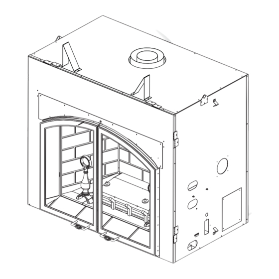
Page 5: Dimensions
DIMENSIONS 5" DIA. 8" DIA. 46 ¾” INLET 10 " 29" 30" 40 ¾” 18 ” 27 ¾" 23 ¹/ " 5" ACCESS 7 ³/ " 37 ¼" 37 ¼” PANEL " 46 ¼" ELECTRICAL 48 ¼" INLET GENERAL INSTRUCTIONS WARNING ALWAYS LIGHT THE PILOT WHETHER FOR THE FIRST TIME OR IF THE GAS SUPPLY HAS RAN OUT, WITH THE GLASS DOOR OPENED OR REMOVED. -
Page 6: General Information
The installation must conform with local codes or, in We suggest that our gas absence of local codes, the National Gas and Propane hearth products be installed Installation Code CSA B149.1 in Canada, or the National and serviced by professionals Fuel Gas Code, ANSI Z223.1 / NFPA 54 in the United States. -
Page 7: Rating Plate Information
NTED USING THE APPROPRIAT L'APPAREIL DOIT ÉVACUER SES GAZ EN UTILISANT L'ENSEMBLE FRAMING MATERIALS. FOR FINISHING MATERIALS ARRIÉRE D'ÉVACUATION PROPRE A NAPOLEON. RÉFÉRER AU MANUEL NAPOLEON VENT KITS. SEE OWNERS INSTALLATION MANUAL WNERS INSTALLATION MANU SEE OWNERS MANUAL DESSUS, COTÉS & ARRIÈRE: SELON LES ESPACEURS FOR VENTING SPECIFICS. -
Page 8: Venting
3.0 VENTING WARNING RISK OF FIRE, MAINTAIN SPECIFIED AIR SPACE CLEARANCES TO VENT PIPE AND APPLIANCE. IF VENTING IS INCLUDED WITH SPACERS THE VENT SYSTEM MUST BE SUPPORTED EVERY 3 FEET FOR BOTH VERTICAL AND HORIZONTAL RUNS. USE SUPPORTS OR EQUIVALENT NON-COMBUSTIBLE STRAPPING TO MAINTAIN THE REQUIRED CLEARANCE FROM COMBUSTIBLES. -
Page 9: Venting Lengths And Components
VENTING LENGTHS AND COMPONENTS Use only Wolf Steel, Simpson Dura-Vent, Selkirk Direct Temp, American Metal Amerivent or Metal-Fab venting components. Minimum and maximum vent lengths, for both horizontal and vertical installations, and air terminal locations for either system are set out in this manual and must be adhered to. For Simpson Dura- Vent, Selkirk Direct Temp, American Metal Amerivent and Metal-Fab follow the installation procedure provided with the venting components. -
Page 10: Typical Vent Installation
TYPICAL VENT INSTALLATION 16” MINIMUM 3 FEET MINIMUM 40 FEET MAXIMUM 24” MAXIMUM 13” MINIMUM 53 3/4” MINIMUM PLUS RISE* 40 3/4” 40 3/4” * See “VENTING” section Horizontal runs may have a 0” rise per foot in all cases using Simpson Dura-Vent, Selkirk Direct Temp, Ameri- can Metal Amerivent or Wolf Steel Ltd. -
Page 11: Special Vent Installation
SPECIAL VENT INSTALLATION 3.3.1 PERISCOPE TERMINATION Use the periscope kit to locate the air termination above grade. The periscope must be installed so that when fi nal grading is completed, the bottom air slot is located a minimum 12” above grade. The maximum allowable vent length is 10’. 12”... -
Page 12: Minimum Air Terminal Location Clearances
MINIMUM AIR TERMINAL LOCATION CLEARANCES COVERED BALCONY APPLICATIONS = 3 feet = 2 x ACTUAL feet INSTALLATIONS CANADA U.S.A. 12” 12” Clearance above grade, veranda porch, deck or balcony. 12” Δ 9” Δ Clearance to windows or doors that open. 12”... -
Page 13: Venting Application Flow Chart
VENTING APPLICATION FLOW CHART Horizontal Termination Vertical Termination Vertical rise is equal Vertical rise is equal Vertical rise is less Vertical rise is less to or greater than to or greater than than horizontal run than horizontal run the horizontal run the horizontal run Horizontal run + Horizontal run +... -
Page 14: Top Exit Horizontal Termination
TOP EXIT HORIZONTAL TERMINATION ) < (V See graph to determine the required vertical Simple venting confi guration (only one 90° elbow) rise V for the required horizontal run H REQUIRED VERTICAL RISE IN FEET V 12.5 17.5 HORIZONTAL VENT RUN PLUS OFFSET IN FEET H The shaded area within the lines represents acceptable values for H... - Page 15 ) > (V Simple venting configuration (only one 90° elbow) See graph to determine the required vertical rise V for the required horizontal run H 147” REQUIRED VERTICAL RISE IN INCHES V 57” 19 1/2” 2’ 19.5’ 12.5’ HORIZONTAL VENT RUN PLUS OFFSET IN FEET H The shaded area within the lines represents acceptable values for H and V...
-
Page 16: Vertical Termination
VERTICAL TERMINATION ) < (V Simple venting configurations. See graph to determine the required vertical rise V for the required horizontal run H REQUIRED VERTICAL RISE IN FEET V HORIZONTAL VENT RUN PLUS OFFSET IN FEET H The shaded area within the lines represents acceptable values for H and V For vent configurations requiring one or more 90°... - Page 17 ) > (V Simple venting configurations. See graph to determine the required vertical rise V for the required horizontal run H REQUIRED VERTICAL RISE IN FEET V HORIZONTAL VENT RUN PLUS OFFSET IN FEET H The shaded area within the lines represents acceptable values for H and V For vent configurations requiring more than two 90°...
-
Page 18: Installation
4.0 INSTALLATION WARNING FOR SAFE AND PROPER OPERATION OF THE APPLIANCE, FOLLOW THE VENTING INSTRUCTIONS EXACTLY. ALL INNER EXHAUST AND OUTER INTAKE VENT PIPE JOINTS MAY BE SEALED USING EITHER RED RTV HIGH TEMP SILICONE SEALANT W573-0002 (NOT SUPPLIED) OR BLACK HIGH TEMP MILL PAC W573-0007 (NOT SUPPLIED) WITH THE EXCEPTION OF THE APPLIANCE EXHAUST FLUE COLLAR WHICH MUST BE SEALED USING MILL PAC. -
Page 19: Horizontal Installation
4.1.2 HORIZONTAL INSTALLATION WARNING THE FIRESTOP ASSEMBLY MUST BE INSTALLED WITH THE VENT SHIELD TO THE TOP. TERMINALS MUST NOT BE RECESSED INTO A WALL OR SIDING MORE THAN THE DEPTH OF THE RETURN FLANGE OF THE MOUNTING PLATE. This application occurs when venting through an exterior wall. Having determined the correct height for the air terminal VENT location, cut and frame a hole in the exterior wall as... -
Page 20: Using Flexible Vent Components
USING FLEXIBLE VENT COMPONENTS WARNING DO NOT ALLOW THE INNER FLEX PIPE TO BUNCH UP ON HORIZONTAL OR VERTICAL RUNS AND ELBOWS. KEEP IT PULLED TIGHT. SPACERS ARE ATTACHED TO THE INNER FLEX PIPE AT PREDETERMINED INTERVALS TO MAINTAIN AN EVEN AIR GAP TO THE OUTER FLEX PIPE. -
Page 21: Vertical Air Terminal Installation
4.2.2 VERTICAL AIR TERMINAL INSTALLATION WARNING MAINTAIN A MINIMUM 2” SPACE BETWEEN THE AIR INLET BASE AND THE STORM COLLAR. Fasten the roof support to the roof using the screws provided. The roof support is optional. In this case the venting is to be adequately supported using either an alternate method suitable to the authority having jurisdiction or the optional roof support. -
Page 22: Appliance Vent Connection
4.2.3 APPLIANCE VENT CONNECTION Install the inner fl ex pipe to the appliance. Secure with 3 screws #8 X 1/2” and fl at washers. Seal the joint and screw holes using the high SELF temperature sealant W573-0007 (not supplied). DRILLING SCREWS Install the outer fl... -
Page 23: Gas Installation
GAS INSTALLATION WARNING RISK OF FIRE, EXPLOSION OR ASPHYXIATION. ENSURE THERE ARE NO IGNITION SOURCES SUCH AS SPARKS OR OPEN FLAMES. SUPPORT GAS CONTROL WHEN ATTACHING GAS SUPPLY PIPE TO PREVENT DAMAGING GAS LINE. ALWAYS LIGHT THE PILOT WHETHER FOR THE FIRST TIME OR IF THE GAS SUPPLY HAS RUN OUT WITH THE GLASS DOOR OPENED OR REMOVED. -
Page 24: Framing
5.0 FRAMING WARNING RISK OF FIRE! IN ORDER TO AVOID THE POSSIBILITY OF EXPOSED INSULATION OR VAPOUR BARRIER COMING IN CONTACT WITH THE APPLIANCE BODY, IT IS RECOMMENDED THAT THE WALLS OF THE APPLI- ANCE ENCLOSURE BE “FINISHED” (IE: DRYWALL / SHEETROCK), AS YOU WOULD FINISH ANY OTHER OUTSIDE WALL OF A HOME. - Page 25 When roughing in the appliance, raise the appliance to accommodate for the thickness of the fi nished fl oor ma- terials, i.e. tile, carpeting, hard wood, which if not planned for will interfere with the removal of the hearth strip, which must be removed to access the fi...
-
Page 26: Minimum Clearance To Combustibles
MINIMUM CLEARANCE TO COMBUSTIBLES Minimum clearance to combustible construction from appliance and vent surfaces: Non combustible framing: 0” to stand-offs. Combustible framing: Sides, back, bottom of the unit 0” to stand-offs Non combustible fi nishing: 18” to top of appliance opening Sides 5 3/8”... -
Page 27: Minimum Clearance To Combustible Enclosures
MINIMUM CLEARANCE TO COMBUSTIBLE ENCLOSURES WARNING USE ONLY NON-COMBUSTIBLE MATERIAL SUCH AS CEMENT BOARD, CERAMIC TILE, MARBLE, ETC. WHEN FINISHING TO THE APPLIANCE. DO NOT USE WOOD OR DRYWALL. FACING AND/OR FINISHING MATERIAL MUST NEVER OVERHANG INTO THE APPLIANCE OPENING DO NOT DISTORT OR FORCE THE FRAME KIT COMPONENTS. - Page 28 0” IF NON- 3 1/2” ** COMBUSTIBLE 2” FINISHING IS USED SUCH AS BRICK AND STONE. 7” ** 2” STAND OFF 72” SPACER MINIMUM ENCLOSURE 53 3/4” HEIGHT NON-COMBUSTIBLE MINIMUM PLUS RISE* 2” * See venting section ** Within the appliance enclosure a 7” clearance between the vertical vent run and the combustible materials on the front facing of the enclosure is required.
-
Page 29: Minimum Mantel Clearances
MINIMUM MANTEL CLEARANCES WARNING RISK OF FIRE, MAINTAIN ALL SPECIFIED AIR SPACE CLEARANCES TO COMBUSTIBLES. FAILURE TO COMPLY WITH THESE INSTRUCTIONS MAY CAUSE A FIRE OR CAUSE THE APPLIANCE TO OVERHEAT. ENSURE ALL CLEARANCES (I.E. BACK, SIDE, TOP, VENT, MANTEL, FRONT, ETC.) ARE CLEARLY MAINTAINED. -
Page 30: Finishing
6.0 FINISHING WARNING RISK OF FIRE! NEVER OBSTRUCT THE FRONT OPENING OF THE APPLIANCE. THE FRONT OF THE APPLIANCE MUST BE FINISHED WITH ANY NON-COMBUSTIBLE MATERIALS SUCH AS BRICK, MARBLE, GRANITE, ETC., PROVIDED THAT THESE MATERIALS DO NOT GO BELOW THE SPECIFIED DIMENSION AS ILLUSTRATED. DO NOT STRIKE, SLAM OR SCRATCH GLASS. -
Page 31: Log Shipping Bracket
The curtain assembly can be removed by lifting the rod out from the three hooks at the top inside edge of the door opening. Lift the hearth strip up and away from the front of the appliance. The glass door is secured to the top front edge of the fi... -
Page 32: Decorative Brick Panel Installation
DECORATIVE BRICK PANEL INSTALLATION Remove the hearth strip / screen assembly and glass door. (Refer to leafl et). 6.3.1 Remove the andiron / grate assembly by removing the 6.3.2 2 screws located behind the andirons. SECURING SECURING SCREW SCREW Remove the right log bracket, as shown. Note the posi- 6.3.3 BRACKET BRACKET... -
Page 33: Log Placement
LOG PLACEMENT WARNING FAILURE TO POSITION THE LOGS IN ACCORDANCE WITH THESE DIAGRAMS OR FAILURE TO USE ONLY LOGS SPECIFICALLY APPROVED WITH THIS APPLIANCE MAY RESULT IN PROPERTY DAMAGE OR PERSONAL INJURY. LOGS MUST BE PLACED IN THEIR EXACT LOCATION IN THE APPLIANCE. DO NOT MODIFY THE PROPER LOG POSITIONS, SINCE APPLIANCE MAY NOT FUNCTION PROPERLY AND DELAYED IGNITION MAY OCCUR. -
Page 34: Glowing Embers
NOTE: For propane, remove the screw from the #3 log support bracket. Move the bracket to the right most location, then install the log. BRACKET Place log #4, with the charred branch pointed 6.4.4 inward. Locate the pins into the holes in log#1 and log#2, this will hold the rear log in position. -
Page 35: Operation
7.0 OPERATION WARNING IF YOU DO NOT FOLLOW THESE INSTRUCTIONS EXACTLY, A FIRE OR EXPLOSION MAY RESULT CAUSING PROPERTY DAMAGE, PERSONAL INJURY OR LOSS OF LIFE. ALWAYS LIGHT THE PILOT WHETHER FOR THE FIRST TIME OR IF THE GAS SUPPLY HAS RUN OUT WITH THE GLASS DOOR OPENED OR REMOVED. -
Page 36: Temperature Display
TEMPERATURE DISPLAY • With the system in the “OFF” position, press the 7.4.1 Thermostat Key and the Mode Key at the same °F °C time to change from degrees F to C. • Look at the LCD screen on the Transmitter to 7.4.2 verify that a C or F is visible to the right of the Room Temperature display. -
Page 37: Flame Height
FLAME HEIGHT The remote control has six (6) fl ame levels. With the °F °F system on and the fl ame level at the maximum, press the Down Arrow Key once and it will reduce the fl ame height by one step until the fl ame is turned off. The Up Arrow Key will increase the fl... -
Page 38: Night Lights Tm
7.10 NIGHT LIGHTS The auxiliary function controls the AUX power outlet on °F °F the Control Module which controls the NIGHT LIGHT™. SMART SMART • Use the Mode Key to guide you to the AUX icon. 7.10.1 • Pressing the Up Arrow Key will activate the 7.10.2 NIGHT LIGHT™. -
Page 39: Electrical Information
8.0 ELECTRICAL INFORMATION WARNING DO NOT USE THIS APPLIANCE IF ANY PART HAS BEEN UNDER WATER. CALL A QUALIFIED SERVICE TECHNICIAN IMMEDIATELY TO HAVE THE APPLIANCE INSPECTED FOR DAMAGE TO THE ELECTRICAL CIRCUIT. RISK OF ELECTRICAL SHOCK OR EXPLOSION. DO NOT WIRE 110V TO THE VALVE OR TO THE APPLIANCE WALL SWITCH. -
Page 40: Operating Instructions
9.0 OPERATING INSTRUCTIONS WARNING IF YOU DO NOT FOLLOW THESE INSTRUCTIONS EXACTLY, A FIRE OR EXPLOSION MAY RESULT CAUSING PROPERTY DAMAGE, PERSONAL INJURY OR LOSS OF LIFE. ALWAYS LIGHT THE PILOT WHETHER FOR THE FIRST TIME OR IF THE GAS SUPPLY HAS RUN OUT WITH THE GLASS DOOR OPENED OR REMOVED. -
Page 41: Adjustment
10.0 ADJUSTMENT 10.1 PILOT BURNER ADJUSTMENT Adjust the pilot screw to provide properly sized fl ame. Turn in a clockwise PILOT direction to reduce the gas fl ow. BURNER THERMOPILE Inlet pressure can be checked by turning screw (A) counter- THERMOCOUPLE clockwise until loosened and then placing pressure gauge tubing over the test point. -
Page 42: Flame Characteristics
10.3 FLAME CHARACTERISTICS It’s important to periodically perform a visual check of the pilot and 3/8” - 1/2” burner fl ames. Compare them to the illustrations provided. If any fl ames appear abnormal call a service person. FLAME MUST ENVELOPE UPPER 3/8"... -
Page 43: Maintenance
11.0 MAINTENANCE MAINTENANCE MAINTENANCE WARNING MAINTENANCE TURN OFF THE GAS AND ELECTRICAL POWER BEFORE SERVICING THE APPLIANCE. APPLIANCE MAY BE HOT, DO NOT SERVICE UNTIL APPLIANCE HAS COOLED. DO NOT USE ABRASIVE CLEANERS. CAUTION: Label all wires prior to disconnection when servicing controls. Wiring errors can cause improper and dangerous operation. -
Page 44: Night Light Tm Replacement
11.2 NIGHT LIGHT REPLACEMENT Your appliance comes equipped with our “Night Light™”. The light has been pre-wired and is controlled from the remote control. LENSE FRAME If in the event the lamp or lens needs to be replaced, follow the instructions below. -
Page 45: Remote Receiver Removal
HANDLE HOUSING MAINS VOLTAGE VALVE SUPPLY CORD WING NUT MODULE ON/OFF SWITCH RECEIVER VALVE COMMUNICATION BUS (3 PIN PLATE SLOT 120V AUX OUTLET FAN OUTLET SPARK CONSTANTLY POWERED 120V OUTLET MODULE SPARK MODULE 11.4 REMOTE RECEIVER REMOVAL 11.4.1 Open the right control door by pulling bottom portion away from magnet catch. -
Page 46: Auto Spark" Battery Removal
11.6 “AUTO SPARK” BATTERY REMOVAL This unit is equipped with a spark module that will pro- vide the spark to pilot when the pilot knob is pushed in. It will be necessary to install the “AAA” battery supplied. Install and replace batteries as noted below: 11.6.1 Open the right control door by pulling bottom portion away from magnet catch. -
Page 47: Replacements
ELECTRODE C/W LEAD W680-0015 THERMOPILE W010-1194 NATURAL GAS PILOT ASSEMBLY W010-1201 PROPANE GAS PILOT ASSEMBLY W455-0070 NG PILOT INJECTOR W455-0068 LP PILOT INJECTOR W385-0334 NAPOLEON® LOGO W562-0037 DOOR GASKET (132“) W010-1800 FIRESTOP W010-1202 BURNER W062-0010 BLOWER W660-0041 SPARK SWITCH W660-0071... - Page 48 W300-0086 NIGHT LIGHT™ GLASS W387-0006 NIGHT LIGHT™ LAMP W750-0178 NIGHT LIGHT™ WIRE HARNESS W290-0080 NIGHT LIGHT™ LENSE GASKET W660-0086 SWITCH, FAN CONTROL FLEXIBLE VENT KITS REF NO. GD80 DESCRIPTION GD420 (5 FT) W010-0772 5” FLEX VENT PIPE - (5 FT) C/W SPACERS W730-0012 8”...
- Page 49 12** W415-0695 / A / 06.07.10...
-
Page 50: Trouble Shooting
13.0 TROUBLE SHOOTING WARNING ALWAYS LIGHT THE PILOT WHETHER FOR THE FIRST TIME OR IF THE GAS SUPPLY HAS RAN OUT, WITH THE GLASS DOOR OPEN OR REMOVED. TURN OFF THE GAS AND ELECTRICAL POWER BEFORE SERVICING THE APPLIANCE. APPLIANCE MAY BE HOT, DO NOT SERVICE UNTIL APPLIANCE HAS COOLED. DO NOT USE ABRASIVE CLEANERS. - Page 51 SYMPTOM PROBLEM TEST SOLUTION Main burner goes Pilot fl ame is not large Turn up the pilot fl ame. out; pilot stays on. enough or not engulfi ng Replace pilot assembly. the thermopile. Thermopile shorting. Clean thermopile connection to the valve. Reconnect. Replace thermopile / valve.
- Page 52 SYMPTOM PROBLEM TEST SOLUTION Pilot goes out Gas piping is undersized. Turn on all gas appliances and see if pilot fl ame while standing: fl utters, diminishes or extinguishes, especially Main burner is in when main burner ignites. Monitor appliance supply “OFF”...
-
Page 53: Warranty
NAPOLEON® warrants its stainless steel burners against defects in workmanship and material for life, subject to the following conditions: During the fi rst 10 years NAPOLEON® will replace or repair the defective parts at our option free of charge. From 10 years to life, NAPOLEON®... -
Page 54: Service History
15.0 SERVICE HISTORY 43.1 W415-0695 / A / 06.07.10... - Page 55 16.0 NOTES 44.1 W415-0695 / A / 06.07.10...
- Page 56 44.1 W415-0695 / A / 06.07.10...
Need help?
Do you have a question about the Madison GD80NT and is the answer not in the manual?
Questions and answers