Table of Contents
Advertisement
Quick Links
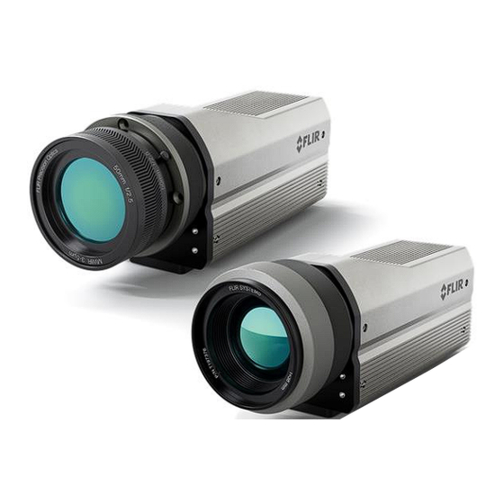
G620a & A6301 Cameras
User's Manual
Revision: A
Issue Date: March 27, 2024
Teledyne Confidential; Commercially Sensitive Business Data
WARNING - This document contains technology subject to the Export Administration Regulations
(EAR) (15 C.F.R. Sections 730- 774). Export or diversion contrary to law is prohibited. (EAR99)
Advertisement
Table of Contents

Subscribe to Our Youtube Channel
Related Manuals for FLIR APLITER G620a


Summary of Contents for FLIR APLITER G620a
- Page 1 G620a & A6301 Cameras User’s Manual Revision: A Issue Date: March 27, 2024 Teledyne Confidential; Commercially Sensitive Business Data WARNING - This document contains technology subject to the Export Administration Regulations (EAR) (15 C.F.R. Sections 730- 774). Export or diversion contrary to law is prohibited. (EAR99)
- Page 2 ©2022 FLIR Systems, Inc. Teledyne Confidential; Commercially Sensitive Business Data G620a & A6301 Camera’s User’s Manual WARNING – EAR Controlled Technology (EAR99)
-
Page 3: Table Of Contents
Table of Contents REVISION HISTORY ............................5 INTRODUCTION ............................. 6 Delivered Camera System Components ................6 Camera Models ....................... 7 Camera Specifications ..................... 7 WARNINGS AND CAUTIONS ........................11 INSTALLATION ............................12 Camera Parts ........................ 12 4.1.1 Status/Indicator LEDs ......................... 12 4.1.2 PoE Connector ........................... - Page 4 8.6.4 Temperature Tab ........................42 8.6.5 Cyber Tab ........................... 42 8.6.6 Firmware & Info Tab ........................46 FLIR CAMTOOLS ............................49 Camera IP Config ......................49 Camera PlayIR ......................50 9.2.1 Menu Bar Functions ........................50 MAINTENANCE ............................57 10.1 Camera Body, Cables, and Accessories ................
-
Page 5: Revision History
1 - Revision History 1 Revision History Version Date Initials Changes 03/27/2024 Initial release Teledyne Confidential; Commercially Sensitive Business Data G620a & A6301 Camera’s User’s Manual WARNING – EAR Controlled Technology (EAR99) -
Page 6: Introduction
Thank you for choosing the FLIR G620a or A6301 camera! The FLIR G620a is an infrared camera for optical gas imaging (OGI) that allows oil and gas operators, and other industrial markets, a solution for continuous and autonomous leak detection. The FLIR G620a is used in industrial settings such as natural gas processing plants, biogas and power generation plants and helps to protect the environment by tracing leaks of methane. -
Page 7: Camera Models
Array Format 640x512 Frame Rate 30Hz (user selectable 1Hz - 30Hz) Detector Type Hot MWIR T2SLS Sensor Cooling FLIR FL100 Linear Cooler Pixel Pitch 15µm G620a: 3.2µm – 3.4µm Spectral Range A6301: 3.0µm – 5.0µm Sensitivity (NEdT) < 15mK Typical (33mS integration @ 25C) - Page 8 2 - Introduction Ambient Drift Compensation ≤100ºC: ±2ºC Accuracy >100ºC: ±2% of reading Optics – G620a Model Number 29434-201 29434-202 29434-203 6.0ºx4.8º 14.4ºx11.5º 23.6ºx19.0º Focal Length 92mm 38mm 23mm f/1.59 Focus Motorized Optical Zoom Optics – A6301 Model Number 29433-206 29433-207 29433-208 31.5ºx25.5º...
- Page 9 • Manual System Integration Video Type IP (RTSP) GigE Vision Provided Display and Web Browser FLIR Camera PlayIR Control Software User Custom Control REST API GeniCam Ethernet 100/1000 Mbps Digital I/O Input: Two 24V inputs...
- Page 10 2 - Introduction DC Voltage Range 15V-56V Environmental IP Rating (Dust & IP50 Water Ingress) Operating -20ºC to 50ºC Temperature Shock 25g, 6ms; Half sine; +- 500 shocks; X,Y&Z (IAW MIL-STD-810H) Vibration MIL-STD-810H Compliance & Certifications • EMC: 2014/30/EU, WEEE: 2012/19/EU •...
-
Page 11: Warnings And Cautions
3 - Warnings and Cautions 3 Warnings and Cautions For best results and user safety, the following warnings and precautions should be followed when handling and operating the camera: Warnings and Cautions ➢ Do not open the camera body for any reason. Disassembly of the camera (including removal of the cover) can cause permanent damage and will void the warranty. -
Page 12: Installation
4 - Installation 4 Installation 4.1 Camera Parts Item Description Removable lens (G620a lens shown) Base camera body Ethernet/PoE connector, X-coded Status/Indicator LEDs Auxiliary Connector, A-coded Factory Reset Button microSD Card Slot (not currently implemented) 4.1.1 Status/Indicator LEDs Description Power – When illuminated, appropriate power has been applied to the camera and the camera is “on”. -
Page 13: Poe Connector
4 - Installation Ethernet – LED blinks indicating network connected and activity. Cold – When illuminated, indicates the detector has reached operational temperature and images are now valid. Fault – When illuminated, indicates the camera has detected a fault. Also tied to the Fault I/O on the Aux connector. -
Page 14: Aux Connector
4 - Installation 4.1.3 AUX Connector The AUX connector contains Digital I/O, Fault Indicator, External Sync, and optional power input. AUX Connector Direction Signal Input - Aux Pwr Input + Aux Pwr (18-56V, 25W) See Figure 1 Fault A See Figure 1 Fault B See Figure 1 Dig Out 0, A... - Page 15 4 - Installation 4.1.3.1 AUX Pigtail Cable, T911852ACC The T911852ACC is a pigtail cable that can be purchased separately for use with the camera’s AUX connector. T911852-B Pigtail Connector Pin Wire Color Signal Black - Aux Pwr + Aux Pwr (18-56V, 25W) Green Fault A Purple...
-
Page 16: Factory Reset Button
4 - Installation 4.1.4 Factory Reset Button Pressing, and holding, the Factory Reset Button on the rear panel performs the following functions: Hold Button for Results Less than 1 second Nothing Reboot – Reboots the camera and returns to its last Greater than 1 second but less than 4 seconds saved settings... -
Page 17: Connecting To The Camera For The First Time
If you do not know the camera’s IP Address, or if the address is incompatible with your current network, you can use FLIR IP Config (see Section 9.1) to get an IP address that can be used to connect with. Then use the Web Browser to change the camera’s IP settings. -
Page 18: Default Network Configuration
5 - Connecting to the Camera for the First Time 5.3 Default Network Configuration Field Default Value Settings Static IP Address 192.168.0.250 Host Name <family>-<serial number> • Examples: o G620a-G1001 o A6301-A10001 • Model and Serial Number can be found on the camera’s rear panel Login User Name = admin... -
Page 19: Camera Theory Of Operation
6 - Camera Theory of Operation 6 Camera Theory of Operation 6.1 Basic Camera Components The figure below shows the basic parts of the camera regardless of camera family or model. The G620a and A6301 camera families are defined by the IDCA, while the optics define the model within the camera family. - Page 20 6 - Camera Theory of Operation also contains a Cold Filter in front of the FPA which limits the spectrum response to 3.2μm to 3.4μm so that it can be optimized to energy emitted by gas. The 3.0μm to 5.0μm range places these cameras in the Mid Wave IR portion of the overall energy spectrum, and as such, these cameras are often described as MWIR cameras;...
-
Page 21: Simplified Image Data Processing Pipeline
6 - Camera Theory of Operation 6.2 Simplified Image Data Processing Pipeline 6.2.1 Calibration Calibration is a two-part process in the image data processing pipeline consisting of applying a Non- Uniformity Correction (NUC) and a Temperature Conversion. Both of which consist of a series of algorithms with variables that are unique to every camera. - Page 22 6 - Camera Theory of Operation 6.2.1.1 Non-Uniformity Correction (NUC) Simply stated, each pixel in an IR camera has its own circuitry associated with it and therefore reacts independently from the other pixels in the array. While the pixels respond linearly, the individual circuity results in each pixel having its own unique slope and offset component typical in a linear system which vary slightly compared to the other pixels in the array.
-
Page 23: Agc
6 - Camera Theory of Operation The FFC will result in a slightly modified NUC table, but those modification are not saved in the table between power cycles as it is based on typical run time changes. 6.2.1.3 Bad Pixel Replacement The final part of the NUC correction is a Bad Pixel Replacement. - Page 24 6 - Camera Theory of Operation 6.2.2.1 Linear AGC The simplest method to scale the 16-bit data down to 8-bits is by dividing each value by 256, as shown in Figure 4. This greatly reduces the resolution of the display and results in the 8-bit data covering large areas of the temperate range that are not being used by the image.
- Page 25 6 - Camera Theory of Operation Figure 6 – Linear Scaling of a Soldering Iron Plateau Equalization (PE) is a non-linear scaling algorithm that basically takes the top 256 peaks in the histogram and maps them to the 8-bit data output. This ensures that the mapping maximizes over where the data is changing and ignores unused data values, as shown in Figure 7.
-
Page 26: Digital Zoom
6 - Camera Theory of Operation Figure 8 – PE Scaling Over Entire Images vs ROI From Figure 8, in the left image the soldering iron forces the PE scaling to cover a wider range and therefore little contrast can be seen in the background. The right image uses an AGC ROI that excludes the soldering iron. -
Page 27: Radiometric Vs Nonradiometric Data
6 - Camera Theory of Operation 6.2.5 Radiometric vs Nonradiometric Data Radiometric Data is an array of 16-bit values that have meaning and can be used for measurements. The data has been corrected, or NUCed, and may or may not have been converted to temperatures (some users prefer to perform the Temperature Conversion on the host side). -
Page 28: Operating The Camera
7 - Operating the Camera 7 Operating the Camera The camera has two distinct paths for imaging, control, and user GUI/display. Which path to use typically depends on whether the user is interested in Radiometric or Nonradiometric data. 7.1 Non-Radiometric Data Users For users who are not interested in actual temperature measurements with the camera. -
Page 29: Opening Stream In Vlc
7 - Operating the Camera 7.4.1 Opening Stream in VLC Figure 9 shows an example of opening Stream2 in VLC Media Player. Figure 9 – Opening Stream 2 in VLC Example Teledyne Confidential; Commercially Sensitive Business Data G620a & A6301 Camera’s User’s Manual WARNING –... -
Page 30: Web Browser
8 - Web Browser 8 Web Browser This chapter contains information about how to control the camera using the Web Browser interface. From the host computer, open a web browser (such as Google Chrome® which this guide reflects) and type the camera’s IP address (or optionally the <Hostname>.local) in the browser’s address bar. -
Page 31: Video Page
8 - Web Browser • Slider Bar – Moves the lens through its travel range. • Encoder Counts – The focus position in encoder counts. Used for focus point reference so the focus position can be returned to a predetermined spot. Digital Zoom –... - Page 32 8 - Web Browser To change the settings for a particular video stream, click the relevant button (Stream1 or Stream2). The stream resolution is fixed at 640x512 and the frame rate follows the camera’s frame rate. The codec determines which settings are available. The values of those settings can have a significant impact on the quality and bandwidth requirements of the video stream.
-
Page 33: Thermal Page
Quality - can be set between 0-100. Setting a higher value can increase the video stream's bandwidth requirements. Teledyne FLIR recommends setting a value no higher than 80. Enable Multicast By default, multicast is enabled. Multicast video packets are shared by streaming clients. Additional clients do not cause bandwidth to increase as dramatically as with unicast. - Page 34 8 - Web Browser High Sensitivity Mode (HSM) - A FLIR-patented algorithm first introduced in the GasFindIR cameras that allows the user to see small temperature changes in the scene. Palette - Select the color palette the camera uses to indicate detected levels of thermal energy.
- Page 35 8 - Web Browser Advanced Sensor Settings • FFC Mode – Selects how and when the FFC is performed. o Auto – performs a FFC automatically based on the Auto FFC When criteria. o Manual – performs a FFC only when the Perform FFC button is selected, uses the internal flag.
-
Page 36: I/O Page
8 - Web Browser • To change the size of the ROI - Hover over the handle in the bottom-right corner of the ROI and then click and drag it. • To move the entire ROI - Hover over the ROI, and then click and drag it. 8.4 I/O Page The I/O Page gives control over the Digital Input and Output pins on the camera’s AUX connector, see Section 4.1.3... -
Page 37: Osd Page
8 - Web Browser Figure 10 - Aux Connector Digital Out 0/1 and Fault Pins 8.5 OSD Page For each IP video stream (stream1, stream2), an On-Screen Display (OSD) consisting of Camera Name and the Date & Time can be enabled and configured. Enable –... -
Page 38: Camera System Settings
8 - Web Browser 8.6 Camera System Settings Users assigned the admin or expert role can click System Settings on the bottom left corner of the Home Page to access the following configuration pages: • Network • Date & Time •... - Page 39 8 - Web Browser DHCP Static Hostname Mode Select DHCP or Static Static only Hostname Camera’s IP address Netmask Default value is 255.255.255.0 Gateway The Hostname Mode can be set to DHCP or Static (default). If set to Static, specify the Hostname for the camera’s server.
-
Page 40: Date & Time Tab
8 - Web Browser 8.6.2 Date & Time Tab The camera’s date and time can be synchronized with a NTP server, or it can utilize its own internal battery backup Real Time Clock (RTC) which can be manually set by the user and retain its time while the camera is turned off. - Page 41 8 - Web Browser user expert admin • View Live Video Access and use all pages, Access and use all • View Help Page menus, controls, and pages, menus, controls, • Log out settings except the Users and settings, including the Users Tab (cannot delete the default admin user)
-
Page 42: Temperature Tab
8 - Web Browser 8.6.4 Temperature Tab Various thermometers are placed inside the camera and the readings are displayed on the Temperature Tab. This gives the user an idea of the camera’s temperature and indicates if the camera is overheating or has overheated. 8.6.5 Cyber Tab The Cyber page provides security configurations settings for: •... - Page 43 8 - Web Browser 8.6.5.1.1 To generate and install a self-signed certificate for TLS/HTTPS 1. In the Certificates section and Certification area, select TLS/HTTPS and Self-Signed. 2. Enter information such as country code, city name, and organization name. 3. Click Create Certificate. 4.
- Page 44 8 - Web Browser b. Select the appropriate key file. c. Click Upload File. 3. If you are uploading a third-party CA signed certificate, select and upload the Public Key, Private Key, and CA Certificate. 4. Verify that the camera certificate files are valid and make sure Certificates are OK appears under the certificate information, under Download certificate.
- Page 45 If you do not know how to configure these settings, contact your network administrator. 8.6.5.4 Services You can enable or disable: • Digest authentication for the FLIR CGI control interface. Default is On (enabled). • RTSP authentication. When disabled, accessing the camera's video streams does not require authentication. Default is On (enabled).
-
Page 46: Firmware & Info Tab
8 - Web Browser Caution Disabling services and ports can affect product functionality. If you do not know how to configure these settings, contact your network administrator. 8.6.5.6 IP Filter The camera's IP filter can deny or allow access according to specific IPv4 addresses that you define. By default, the IP filter is disabled (Off). - Page 47 8 - Web Browser • Reboot the camera. • Enable logs, define a log level, and download system information. • Download or upload a configuration backup file. • Configure camera's analog video output. • Enable the camera's external illumination feature. 8.6.6.1 Changing the Camera’s Name Specify a unique, friendly name for the camera, using only alphanumeric characters.
- Page 48 8 - Web Browser • Reboot – Reboots the camera and returns to its last saved settings. Resetting the camera can also be performed by the Reset button on the Rear Panel, see Section 4.1. 8.6.6.4 Support System Info To retrieve the camera’s log files, click Download. Set the logging detail up to four levels, higher log levels increase the size of the log file.
-
Page 49: Flir Camtools
9 - FLIR CamTools 9 FLIR CamTools FLIR CamTools is a suite of software tools designed for the FLIR cooled cameras. Two of those tools, IP Config and Camera PlayIR, are particularly useful with the G620a and A6301 camera families. -
Page 50: Camera Playir
9 - FLIR CamTools 9.2 Camera PlayIR Camera PlayIR is a utility program that provides a basic user application for controlling and viewing live streaming video from a camera. It uses the GigE Vision and GenI Cam standards. The application can be found under the Windows Start menu. - Page 51 9 - FLIR CamTools Unlink – select to disconnect from the camera Fit Screen – adjust the zoom to fit the image to the screen. Otherwise, use the mouse wheel to zoom in and Color Pallet – use to select the color pallet to apply to the image Camera Controller –...
- Page 52 9 - FLIR CamTools If the Last Camera listed is not the one currently connected to the host, or if there is no camera listed, then a camera scan is required. This is performed by pressing the Refresh button. Once the scan is complete, all cameras connected to the host computer will be displayed under Found Cameras.
- Page 53 4) Image Orientation – Flips the image horizontally (HFlip) and/or vertically (VFlip). Mainly used when the camera is mounted upside down or sideways. 5) High Sensitivity Mode - A FLIR-patented algorithm first introduced in the GasFindIR cameras that allows the user to see small temperature changes in the scene.
- Page 54 9 - FLIR CamTools b. Auto – perform FFCs based on the Auto FFC Delta Temp and Auto FFC Interval i. Auto FPA Delta Temp – performs an FFC when the temperature has changed by the set degrees. A setting of 0 disables FFCs based on temperature change.
- Page 55 9 - FLIR CamTools 4) AGC Filter - Determines how quickly a scene adjusts when a hot object appears (or disappears) within the AGC ROI. If set to a low value, when a hot object enters the ROI the AGC will adjust more slowly to the hot object, resulting in a more gradual transition.
- Page 56 9 - FLIR CamTools 9.2.1.8 Minimap Displays the entire image in a smaller window. Used when zoomed in with the main window to give reference to where the zoomed window is in the overall image. 9.2.1.9 Data Display Value Select the desired data value to be shown when the cursor is hovering over a pixel. Counts, Radiance, or Temperature 9.2.1.10 Data Display Units...
-
Page 57: Maintenance
10 - Maintenance 10 Maintenance 10.1 Camera Body, Cables, and Accessories The camera body, cables and accessories may be cleaned by wiping with a soft cloth. To remove stains, wipe with a soft cloth moistened with a mild detergent solution and wrung dry, then wipe with a dry soft cloth. -
Page 58: Appendix A - G620A Mechanical Dimensions
10 - Maintenance Appendix A - G620a Mechanical Dimensions Teledyne Confidential; Commercially Sensitive Business Data G620a & A6301 Camera’s User’s Manual WARNING – EAR Controlled Technology (EAR99) - Page 59 10 - Maintenance Teledyne Confidential; Commercially Sensitive Business Data G620a & A6301 Camera’s User’s Manual WARNING – EAR Controlled Technology (EAR99)
- Page 60 10 - Maintenance Teledyne Confidential; Commercially Sensitive Business Data G620a & A6301 Camera’s User’s Manual WARNING – EAR Controlled Technology (EAR99)
-
Page 61: Appendix B - A6301 Mechanical Dimensions
10 - Maintenance Appendix B - A6301 Mechanical Dimensions Teledyne Confidential; Commercially Sensitive Business Data G620a & A6301 Camera’s User’s Manual WARNING – EAR Controlled Technology (EAR99) - Page 62 10 - Maintenance Teledyne Confidential; Commercially Sensitive Business Data G620a & A6301 Camera’s User’s Manual WARNING – EAR Controlled Technology (EAR99)
- Page 63 10 - Maintenance Teledyne Confidential; Commercially Sensitive Business Data G620a & A6301 Camera’s User’s Manual WARNING – EAR Controlled Technology (EAR99)
Need help?
Do you have a question about the APLITER G620a and is the answer not in the manual?
Questions and answers