Table of Contents
Advertisement
Quick Links
Advertisement
Table of Contents

Related Manuals for ProSoft Technology ProLinx DNPS


Summary of Contents for ProSoft Technology ProLinx DNPS
- Page 1 ProLinx DNPS ProLinx Gateway DNP 3.0 Slave December 01, 2009 USER MANUAL...
-
Page 2: Important Installation Instructions
32K maximum HTML page size (previously limited to 16K) To upgrade a previously purchased Series C model: Contact your ProSoft Technology distributor to order the upgrade and obtain a Returned Merchandise Authorization (RMA) to return the unit to ProSoft Technology. -
Page 3: Your Feedback Please
ProSoft Technology Product Documentation In an effort to conserve paper, ProSoft Technology no longer includes printed manuals with our product shipments. User Manuals, Datasheets, Sample Ladder Files, and Configuration Files are provided on the enclosed CD-ROM, and are available at no charge from our web site: www.prosoft-technology.com Printed documentation is available for purchase. -
Page 5: Table Of Contents
Important Installation Instructions ....................... 2 Your Feedback Please........................3 ® ProSoft Technology Product Documentation..................3 Guide to the ProLinx DNPS User Manual Start Here ProLinx Reference Guide ..................9 Install ProSoft Configuration Builder Software ............9 Using ProSoft Configuration Builder ...............10 DNPS Protocol Configuration..................14 Download the Project to the Module ...............28... - Page 6 ProLinx DNPS ♦ ProLinx Gateway Contents DNP 3.0 Slave User Manual Page 6 of 86 ProSoft Technology, Inc. December 1, 2009...
-
Page 7: Guide To The Prolinx Dnps User Manual
Start Here ProLinx DNPS ♦ ProLinx Gateway User Manual DNP 3.0 Slave Guide to the ProLinx DNPS User Manual Function Section to Read Details → Introduction Start Here (page 9) This Section introduces the customer to the gateway. Included are: package contents,... - Page 8 ProLinx DNPS ♦ ProLinx Gateway Start Here DNP 3.0 Slave User Manual Page 8 of 86 ProSoft Technology, Inc. December 1, 2009...
-
Page 9: Start Here
Download the Project to the Module............28 For most applications, the installation and configuration steps described in this section will work without additional programming. ProSoft Technology strongly recommends that you complete the steps in this chapter before developing a custom application. -
Page 10: Using Prosoft Configuration Builder
ProLinx DNPS ♦ ProLinx Gateway Start Here DNP 3.0 Slave User Manual To install ProSoft Configuration Builder from the Product CD-ROM Insert the ProSoft Solutions Product CD-ROM into the CD-ROM drive of your PC. Wait for the startup screen to appear. - Page 11 The following illustration shows the ProSoft Configuration Builder window with a new project. Your first task is to add the ProLinx DNPS module to the project. Use the mouse to select D in the tree view, and then click the...
- Page 12 ProLinx DNPS ♦ ProLinx Gateway Start Here DNP 3.0 Slave User Manual On the shortcut menu, choose C . This action opens the HOOSE ODULE dialog box. HOOSE ODULE In the P area of the dialog box, select P RODUCT...
- Page 13 1.3.2 Set Module Parameters Notice that the contents of the information pane and the configuration pane changed when you added the ProLinx DNPS module to the project. At this time, you may wish to rename the "Default Project" and "Default Location"...
-
Page 14: Dnps Protocol Configuration
Class 0 poll. The maximum packet size for a Class 0 poll is 2048 bytes. A DNP Message Size Calculator is available on the ProSoft Technology web site. This calculator will help you ensure that the packet size fits within this requirement. - Page 15 Start Here ProLinx DNPS ♦ ProLinx Gateway User Manual DNP 3.0 Slave DNP Database Offset 0 to 3999 Offset in which to place DNP data. Binary Inputs 0 to 500 Number of words for digital input points to configure in the DNP slave device.
- Page 16 ProLinx DNPS ♦ ProLinx Gateway Start Here DNP 3.0 Slave User Manual Float Outputs 0 to 250 points Number of floating point output points to configure in the DNP slave device. Each point will occupy a two-word area in the module's memory.
- Page 17 Start Here ProLinx DNPS ♦ ProLinx Gateway User Manual DNP 3.0 Slave Stop Bits 1 or 2 Stop bits signal the end of a character in the data stream. For most applications, use one stop bit. For slower devices that require more time to re-synchronize, use two stop bits.
- Page 18 ProLinx DNPS ♦ ProLinx Gateway Start Here DNP 3.0 Slave User Manual Connect Timeout 0 to 65535 Defines the number of milliseconds to wait for the CD signal to be set high. The CD signal indicates a connection is made using a dial-up modem.
- Page 19 Start Here ProLinx DNPS ♦ ProLinx Gateway User Manual DNP 3.0 Slave CD Idle Time 0 to 32000 Defines the minimum number of milliseconds to wait before transmitting a message after the CD signal is recognized as low. CD Random Time...
- Page 20 ProLinx DNPS ♦ ProLinx Gateway Start Here DNP 3.0 Slave User Manual BO DB Trigger Yes or No Causes the last values to not match the database values when the DNP master sends a BO command to the module. This can be used to cause the module to issue a conditional write command on the other protocol interface, even if the value received is the same as received previously.
- Page 21 Start Here ProLinx DNPS ♦ ProLinx Gateway User Manual DNP 3.0 Slave Data Link Confirm Tout 1 to 65535 milliseconds Time period to wait for Master Data Link confirmation of last frame sent. This time is in milliseconds. This parameter is only used if the frame is sent with confirmation requested.
- Page 22 ProLinx DNPS ♦ ProLinx Gateway Start Here DNP 3.0 Slave User Manual Unsol Resp Delay 0 to 65535 milliseconds Maximum number of 1 millisecond intervals to wait after an event occurs before sending an unsolicited response message. If set to 0, only use minimum number of events.
- Page 23 Start Here ProLinx DNPS ♦ ProLinx Gateway User Manual DNP 3.0 Slave Point # This is the information object address of the point. Class Class 1 - Highest priority Class 2 - Middle priority Class 3 - Lowest priority 0 - Disable.
- Page 24 ProLinx DNPS ♦ ProLinx Gateway Start Here DNP 3.0 Slave User Manual 1.4.4 [DNP Slave Float Inputs] This area is to override the class (3) and debased for the single float database. The point # is not the address in the analog database, but is the offset from the start of the single floating-point database.
- Page 25 Start Here ProLinx DNPS ♦ ProLinx Gateway User Manual DNP 3.0 Slave 1.4.5 [DNP Slave Double Inputs] This area is to override the class (3) and deadband for the double float database. The point # is not the address in the analog database, but is the offset from the start of the double floating-point database.
- Page 26 ProLinx DNPS ♦ ProLinx Gateway Start Here DNP 3.0 Slave User Manual You can also rearrange the byte and/or word order during the copy process, for example, to convert floating-point values to the correct format for a different protocol. You can also use the Data Map to condense widely dispersed data into one contiguous data block, making it easier to access.
- Page 27 Start Here ProLinx DNPS ♦ ProLinx Gateway User Manual DNP 3.0 Slave To Address 0 to highest User Data Register Address The destination for the copy is always within the User Data registers area. Take care to specify a destination address that will not overwrite data that may be required for other purposes.
-
Page 28: Download The Project To The Module
ProLinx DNPS ♦ ProLinx Gateway Start Here DNP 3.0 Slave User Manual Delay Preset This parameter sets an interval for each [Data Map] copy operation. The value you put for the Delay Preset is not a fixed amount of time. It is the number of firmware scans that must transpire between copy operations. - Page 29 Start Here ProLinx DNPS ♦ ProLinx Gateway User Manual DNP 3.0 Slave Open the P menu, and then choose M . The ROJECT ODULE OWNLOAD program will scan your PC for a valid com port (this may take a few seconds).
- Page 30 ProLinx DNPS ♦ ProLinx Gateway Start Here DNP 3.0 Slave User Manual Page 30 of 86 ProSoft Technology, Inc. December 1, 2009...
-
Page 31: Diagnostics And Troubleshooting
You can connect directly from your computer’s serial port to the serial port on the module to view configuration information, perform maintenance, and send (upload) or receive (download) configuration files. ProSoft Technology recommends the following minimum hardware to connect your computer to the module: 80486 based processor (Pentium preferred) ProSoft Technology, Inc. - Page 32 ProLinx DNPS ♦ ProLinx Gateway Diagnostics and Troubleshooting DNP 3.0 Slave User Manual 1 megabyte of memory At least one UART hardware-based serial communications port available. USB-based virtual UART systems (USB to serial port adapters) often do not function reliably, especially during binary file transfers, such as when uploading/downloading configuration files or module firmware upgrades.
- Page 33 Diagnostics and Troubleshooting ProLinx DNPS ♦ ProLinx Gateway User Manual DNP 3.0 Slave This action opens the D dialog box. IAGNOSTICS Press [?] to open the Main Menu. Important: The illustrations of configuration/debug menus in this section are intended as a general guide, and may not exactly match the configuration/debug menus in your own module.
- Page 34 ProLinx DNPS ♦ ProLinx Gateway Diagnostics and Troubleshooting DNP 3.0 Slave User Manual If you are still not able to establish a connection, contact ProSoft Technology for assistance. Navigation All of the sub-menus for this module contain commands to redisplay the menu or return to the previous menu.
-
Page 35: Led Indicators
Diagnostics and Troubleshooting ProLinx DNPS ♦ ProLinx Gateway User Manual DNP 3.0 Slave LED Indicators Troubleshooting the operation of the DNP Slave port can be performed using several methods. The first and quickest is to scan the LEDs on the module to determine the existence and possibly the cause of a problem. -
Page 36: Serial Port Dnps Error And Status Data
ProLinx DNPS ♦ ProLinx Gateway Diagnostics and Troubleshooting DNP 3.0 Slave User Manual 2.2.3 4101 Series LEDs State Description Power Power is not connected to the power terminals. Power is connected to the power terminals. Verify that the other LEDs Green Solid for operational and functional status light. -
Page 37: Product
Diagnostics and Troubleshooting ProLinx DNPS ♦ ProLinx Gateway User Manual DNP 3.0 Slave 2.3.1 Viewing Error and Status Data The following topics list the register addresses that will contain error and status data. You use the Database View option to view the contents of these registers. - Page 38 ProLinx DNPS ♦ ProLinx Gateway Diagnostics and Troubleshooting DNP 3.0 Slave User Manual Internal Variable Name Description Database Address 1013 DNP Slave Binary Input Event count This value contains the total number of binary input events that have occurred. 1014...
- Page 39 Diagnostics and Troubleshooting ProLinx DNPS ♦ ProLinx Gateway User Manual DNP 3.0 Slave Internal Variable Name Description Database Address 1028 DNP Slave user data overflow error This value counts the number of times (Transport Layer Error) the application layer receives a message fragment buffer which is too small.
- Page 40 ProLinx DNPS ♦ ProLinx Gateway Diagnostics and Troubleshooting DNP 3.0 Slave User Manual Page 40 of 86 ProSoft Technology, Inc. December 1, 2009...
-
Page 41: Reference
Reference ProLinx DNPS ♦ ProLinx Gateway User Manual DNP 3.0 Slave Reference In This Chapter Product Specifications ................41 Communication Port Cables..............44 Functional Overview................50 DNP Collision Avoidance............... 64 IIN Response: Slave Port ..............65 IIN Bit Definitions................... 66 Event Size Computation ................ - Page 42 ProLinx DNPS ♦ ProLinx Gateway Reference DNP 3.0 Slave User Manual Type Specifications DNP Slave Node address 0 to 65534 (software selectable) Status Data Error codes, counters and port status available per configured slave port 3.1.2 Serial Port Specifications Type...
-
Page 43: Hardware Specifications
Reference ProLinx DNPS ♦ ProLinx Gateway User Manual DNP 3.0 Slave 3.1.3 Functional Specifications - DNP 3.0 Slave The DNP 3.0 Slave driver provides extensive support for Slave implementations of the protocol. The serial port on the gateway is user-configurable to support the DNP 3.0 protocol (Slave, Error Checking, Baud rate, and so on). -
Page 44: Communication Port Cables
ProLinx DNPS ♦ ProLinx Gateway Reference DNP 3.0 Slave User Manual Specification Description Ethernet Port 10Base-T half duplex RJ45 Connector Link and Activity LED indicators (Ethernet protocol gateways Electrical Isolation 1500 V rms at 50 Hz to 60 Hz for 60 s, applied as only) specified in section 5.3.2 of IEC 60950: 1991... - Page 45 Reference ProLinx DNPS ♦ ProLinx Gateway User Manual DNP 3.0 Slave Each serial port is a Mini-DIN physical connection. A 6-inch 'Mini-DIN to DB-9M' cable is provided for each active protocol port. The DB-9M provides connections for RS-232, RS-422 and RS-485, as well as for the Debug port. The diagrams in the following topics detail the pin assignments for several possible physical connections.
- Page 46 ProLinx DNPS ♦ ProLinx Gateway Reference DNP 3.0 Slave User Manual Port 0, 1, 2, 3: RS-232 - Null Modem (DTE without Hardware Handshaking) This type of connection can be used to connect the gateway to a computer or field device communication port.
- Page 47 Reference ProLinx DNPS ♦ ProLinx Gateway User Manual DNP 3.0 Slave Port 0, 1, 2, 3: RS-422 Interface Connections The following illustration applies when the RS-422 interface is selected. Port 0, 1, 2, 3: RS-485 Interface Connections The following illustration applies when the RS-485 interface is selected.
- Page 48 ProLinx DNPS ♦ ProLinx Gateway Reference DNP 3.0 Slave User Manual Collision Avoidance (DNP modules only) The RTS line is controlled by the RTS on and off parameters set for the port. If the CTS line is used (usually only required for half-duplex modems and not defined for use in the DNPS specification), the RTS and CTS lines must either be connected together or connected to the modem.
- Page 49 Reference ProLinx DNPS ♦ ProLinx Gateway User Manual DNP 3.0 Slave 3.2.3 Configuration/Debug Port This port is physically an 8-pin Mini-DIN connector. A Mini-DIN to DB-9Male adapter cable is included with the module. This port permits a PC based terminal emulation program to view configuration and status data in the module and to control the module.
-
Page 50: Functional Overview
ProLinx DNPS ♦ ProLinx Gateway Reference DNP 3.0 Slave User Manual Functional Overview The DNP 3.0 Slave protocol driver exists in a single port (DNPS) implementation only. The DNPS port operates in a slave mode only, supporting the DNP 3.0 protocol in a Level 2 implementation. -
Page 51: Module Internal Database
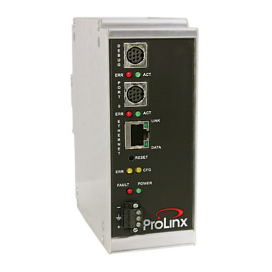
Reference ProLinx DNPS ♦ ProLinx Gateway User Manual DNP 3.0 Slave The relationship between the port labeling on the front of the ProLinx module and the application is as follows: Port Label Function Debug Debug/Configuration Port 0 DNP Slave Port... - Page 52 ProLinx DNPS ♦ ProLinx Gateway Reference DNP 3.0 Slave User Manual Data Area Data Size Binary Outputs 1 word per 16 points Analog Outputs 1 word per point Float Output 2 words per point Double Output 4 words per point...
- Page 53 Reference ProLinx DNPS ♦ ProLinx Gateway User Manual DNP 3.0 Slave The float and double point numbers are offset based on the analog count number since the float and double point are in fact analog variations. The following table shows how the points are generated based on an example configuration.
- Page 54 ProLinx DNPS ♦ ProLinx Gateway Reference DNP 3.0 Slave User Manual 3.3.5 Module DNP Protocol Operation Unsolicited Messaging If the module is configured for unsolicited messaging, the module immediately sends an unsolicited response out Port 1 (Primary DNP port) informing the master of a module restart.
- Page 55 Reference ProLinx DNPS ♦ ProLinx Gateway User Manual DNP 3.0 Slave 3.3.6 Designing the system System design defines the data requirements of the system, communication parameters, and module functionality. The application developer should refer to the person responsible for the DNP master and slave device configurations to verify that the functionality and data types required for the whole system are consistent.
- Page 56 ProLinx DNPS ♦ ProLinx Gateway Reference DNP 3.0 Slave User Manual Data Requirements This phase of design defines what data elements are to be interfaced between the other ProLinx protocol and the DNP master. The module provides the following data types:...
- Page 57 Reference ProLinx DNPS ♦ ProLinx Gateway User Manual DNP 3.0 Slave The following illustration shows the interaction of the counter points with the databases. This data is constantly sourced from the processor and placed in the module’s internal database. This information is available to the remote master for monitoring.
- Page 58 ProLinx DNPS ♦ ProLinx Gateway Reference DNP 3.0 Slave User Manual Data Transfer Interface The following figure displays the direction of movement of the DNP database data between the module and the processor. It is important to understand the relationship of the block identifications and the data in the module.
- Page 59 Reference ProLinx DNPS ♦ ProLinx Gateway User Manual DNP 3.0 Slave DNP Digital Input Data This data type stores the binary value of 1 or 0. The size of this data area is determined from the configuration parameter Binary Inputs (number of words, each containing 1 binary input point).
- Page 60 ProLinx DNPS ♦ ProLinx Gateway Reference DNP 3.0 Slave User Manual DNP Digital Output Data This data type stores digital control and command state data received from the DNP master unit with a value of 1 or 0. The size of this data area is determined from the configuration parameter Binary Outputs (defines number of words, each containing 1 binary output point).
- Page 61 Reference ProLinx DNPS ♦ ProLinx Gateway User Manual DNP 3.0 Slave DNP Counter Data This data type stores accumulated count data. These data are stored in the module in a double word value and have a data range of 0 to 4,294,967,296. The size of this data area is determined from the configuration parameter Counters.
- Page 62 ProLinx DNPS ♦ ProLinx Gateway Reference DNP 3.0 Slave User Manual DNP Analog Input Data This data type stores analog data with a data range of 0 to 65535 or -32768 to 32767. The size of this data area is determined from the configuration parameter Analog Inputs.
- Page 63 Reference ProLinx DNPS ♦ ProLinx Gateway User Manual DNP 3.0 Slave DNP Analog Output Data This data type stores analog values sent from the DNP master unit to the module and the other protocol with a data range of 0 to 65535 or -32768 to 32767. The size of this data area is determined from the configuration parameter Analog Outputs.
-
Page 64: Dnp Collision Avoidance
ProLinx DNPS ♦ ProLinx Gateway Reference DNP 3.0 Slave User Manual DNP Collision Avoidance 3.4.1 When Required Collision avoidance is required under to following network configurations: A multi-point network is used (that is, master unit is communicating with several slave units on same physical link). This excludes a dial-up modem network where the master only communicates with one slave at a time in a point-to-point physical link. -
Page 65: Iin Response: Slave Port
Reference ProLinx DNPS ♦ ProLinx Gateway User Manual DNP 3.0 Slave The timing parameters defined above must be set correctly for successful use of the collision avoidance feature. A timing diagram displaying the data and modem control lines used with the collision avoidance scheme is shown below. This example displays the state of the signal lines in transmitting a message from Unit 1 to Unit 2. -
Page 66: Iin Bit Definitions
ProLinx DNPS ♦ ProLinx Gateway Reference DNP 3.0 Slave User Manual Description Time synchronization required from master. The master should write the date and time when this bit is set. After receiving the write command, the bit will be cleared. Events may not be generated until this bit is cleared after a restart if configured by the user. -
Page 67: Event Size Computation
Reference ProLinx DNPS ♦ ProLinx Gateway User Manual DNP 3.0 Slave Description Device trouble. When this bit is set, the data reported by the module may not be that currently present in the other protocol because the block transfer operation is not successful. -
Page 68: Device Profile
ProLinx DNPS ♦ ProLinx Gateway Reference DNP 3.0 Slave User Manual The number of events that can be defined in the system is limited to 400. The event buffer will overflow in systems which are very dynamic unless one of the... - Page 69 Reference ProLinx DNPS ♦ ProLinx Gateway User Manual DNP 3.0 Slave DNP V3.00 DEVICE PROFILE DOCUMENT When reporting Event Data as a slave unit Time-outs while waiting for: Data Link Confirm : Configurable at module start-up (1 to 65535 mSec)
-
Page 70: Subset Definition
ProLinx DNPS ♦ ProLinx Gateway Reference DNP 3.0 Slave User Manual Subset Definition OBJECT REQUEST RESPONSE Var Description Func Qual Func Qual Data NOTES Codes Codes Codes Codes Size (hex) (hex) (bits) Binary Input: All Slave will return variation 1 data... - Page 71 Reference ProLinx DNPS ♦ ProLinx Gateway User Manual DNP 3.0 Slave OBJECT REQUEST RESPONSE Var Description Func Qual Func Qual Data NOTES Codes Codes Codes Codes Size (hex) (hex) (bits) 32-Bit Binary 1, 7, 8, 129, 00, 01 Slave will return this variation...
- Page 72 ProLinx DNPS ♦ ProLinx Gateway Reference DNP 3.0 Slave User Manual OBJECT REQUEST RESPONSE Var Description Func Qual Func Qual Data NOTES Codes Codes Codes Codes Size (hex) (hex) (bits) 16-Bit Frozen Slave will return Unknown Object to Delta Counter...
- Page 73 Reference ProLinx DNPS ♦ ProLinx Gateway User Manual DNP 3.0 Slave OBJECT REQUEST RESPONSE Var Description Func Qual Func Qual Data NOTES Codes Codes Codes Codes Size (hex) (hex) (bits) 16-Bit Frozen Slave will return Unknown Object to Delta Counter...
- Page 74 ProLinx DNPS ♦ ProLinx Gateway Reference DNP 3.0 Slave User Manual OBJECT REQUEST RESPONSE Var Description Func Qual Func Qual Data NOTES Codes Codes Codes Codes Size (hex) (hex) (bits) 16-Bit Frozen Slave will return Unknown Object to Analog Input...
- Page 75 Reference ProLinx DNPS ♦ ProLinx Gateway User Manual DNP 3.0 Slave OBJECT REQUEST RESPONSE Var Description Func Qual Func Qual Data NOTES Codes Codes Codes Codes Size (hex) (hex) (bits) 32-Bit Frozen Slave will return Unknown Object to Analog Event...
- Page 76 ProLinx DNPS ♦ ProLinx Gateway Reference DNP 3.0 Slave User Manual OBJECT REQUEST RESPONSE Var Description Func Qual Func Qual Data NOTES Codes Codes Codes Codes Size (hex) (hex) (bits) Short Floating 3, 4, 5, 17, 28 Echo of Slave will respond to this request...
- Page 77 Reference ProLinx DNPS ♦ ProLinx Gateway User Manual DNP 3.0 Slave OBJECT REQUEST RESPONSE Var Description Func Qual Func Qual Data NOTES Codes Codes Codes Codes Size (hex) (hex) (bits) Storage Object Not Defined Not Defined in DNP Device Profile...
- Page 78 ProLinx DNPS ♦ ProLinx Gateway Reference DNP 3.0 Slave User Manual OBJECT REQUEST RESPONSE Var Description Func Qual Func Qual Data NOTES Codes Codes Codes Codes Size (hex) (hex) (bits) Slave supports the Disable Unsolicited Function Slave supports the Delay Measurement &...
-
Page 79: Support, Service & Warranty
How to Contact Us: Technical Support..........79 Return Material Authorization (RMA) Policies and Conditions....80 LIMITED WARRANTY................81 ProSoft Technology, Inc. (ProSoft) is committed to providing the most efficient and effective support possible. Before calling, please gather the following information to assist in expediting this process:... -
Page 80: Return Material Authorization (Rma) Policies And Conditions
ProLinx DNPS ♦ ProLinx Gateway Support, Service & Warranty DNP 3.0 Slave User Manual Return Material Authorization (RMA) Policies and Conditions The following RMA Policies and Conditions (collectively, "RMA Policies") apply to any returned Product. These RMA Policies are subject to change by ProSoft without notice. -
Page 81: Limited Warranty
Support, Service & Warranty ProLinx DNPS ♦ ProLinx Gateway User Manual DNP 3.0 Slave c) If unit is repaired, charge to Customer will be 30% of current list price (USD) plus freight charges, duties and taxes as applicable. A new purchase order will be required or authorization to use the purchase order submitted for evaluation fee. -
Page 82: Product
ProLinx DNPS ♦ ProLinx Gateway Support, Service & Warranty DNP 3.0 Slave User Manual b) Warranty On Services: Materials and labor performed by ProSoft to repair a verified malfunction or defect are warranteed in the terms specified above for new Product, provided said warranty will be for the period... - Page 83 Support, Service & Warranty ProLinx DNPS ♦ ProLinx Gateway User Manual DNP 3.0 Slave 4.3.4 Intellectual Property Indemnity Buyer shall indemnify and hold harmless ProSoft and its employees from and against all liabilities, losses, claims, costs and expenses (including attorney’s fees and expenses) related to any claim, investigation, litigation or proceeding (whether or not ProSoft is a party) which arises or is alleged to arise from Buyer’s...
-
Page 84: Product
ProLinx DNPS ♦ ProLinx Gateway Support, Service & Warranty DNP 3.0 Slave User Manual 4.3.6 Limitation of Remedies ** In no event will ProSoft or its Dealer be liable for any special, incidental or consequential damages based on breach of warranty, breach of contract, negligence, strict tort or any other legal theory. -
Page 85: Index
Collision Avoidance • 18 Collision Avoidance (DNP modules only) • 48 General Module Status Data • 37 Common Configuration • 25 Guide to the ProLinx DNPS User Manual • 7 Communication Port Cables • 44 Configuration/Debug Port • 49 Connect Timeout • 18 Hardware Specifications •... - Page 86 ProLinx DNPS ♦ ProLinx Gateway Support, Service & Warranty DNP 3.0 Slave User Manual IIN Bit Definitions • 66 RTS On • 17 IIN Response Rules • 64 Slave Port • 65 Important Installation Instructions • 2 Install ProSoft Configuration Builder Software • 9 Second Byte •...
Need help?
Do you have a question about the ProLinx DNPS and is the answer not in the manual?
Questions and answers