
Related Manuals for ProSoft Technology PLX51-PBS


Summary of Contents for ProSoft Technology PLX51-PBS
- Page 1 PLX51-PBS PROFIBUS DP Slave to EtherNet/IP™ Gateway August 29, 2019 v1.0 USER MANUAL...
- Page 2 Page 2 of 83...
-
Page 3: Table Of Contents
Setup ..........................15 Installing the Configuration Software ............... 15 Network Parameters ....................16 GSD File Management ....................20 Creating a New Project ....................23 PLX51-PBS Parameters ....................25 General ....................... 25 PROFIBUS Slave Configuration ................26 Logix ........................27 Advanced ......................29 Module Download ..................... - Page 4 Module Status Monitoring ..................45 PLX51-PBS ......................46 General ............................47 Slave Status ..........................50 General Statistics ........................51 DPV1 Statistics .......................... 54 Live List ............................56 Discovered Nodes ........................56 Ethernet Clients ........................57 TCP/ARP ............................ 57 Device Status ...................... 58 General –...
- Page 5 Warranty Information ................... 81 Index ..........................83 Page 5 of 83...
- Page 6 Page 6 of 83...
-
Page 7: Preface
EtherNet/IP™ Gateway module. The module will hereafter be collectively referred to as PLX51-PBS. The PLX51-PBS can operate only as one or more (emulates up to 10) PROFIBUS DPV0/DPV1 Slaves. This allows EtherNet/IP devices to exchange process, alarming, and diagnostic data with other PROFIBUS DP Master(s). -
Page 8: Features
Preface FEATURES The PLX51-PBS has two Ethernet ports allowing for either a Linear or Ring (Device Level Ring – DLR) Ethernet topology. The Ethernet ports can also be set up for port mirroring allowing for better fault analysis. The PLX51-PBS can synchronize to an NTP Server, allowing for automatic time synchronization. -
Page 9: Additional Information
Resource Link PLX50 Configuration Utility www.prosoft-technology.com Installation PLX51-PBS User Manual www.prosoft-technology.com PLX51-PBS Datasheet Table 1.1 - Additional Information SUPPORT Technical support is provided via the Web (in the form of user manuals, FAQ, datasheets etc.) to assist with installation, operation, and diagnostics. - Page 10 Page 10 of 83...
-
Page 11: Installation
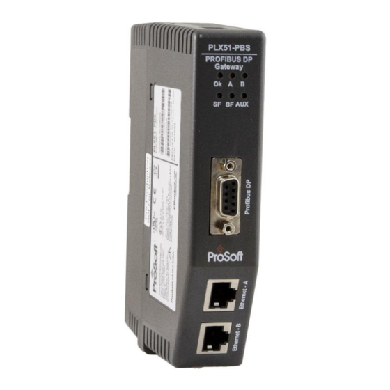
Installation 2. INSTALLATION MODULE LAYOUT The PLX51-PBS has one RS485 PROFIBUS DP port as well as two Ethernet. The Ethernet cable must be wired according to industry standards, which can be found in the Additional Information section of this document. - Page 12 At the bottom of the module, there is one 3-way power connector. Figure 2.2 – PLX51-PBS Power connector The PLX51-PBS has an input voltage range of 10 to 36 VDC, applied to the module via the power connector. The power connector also provides an Earth connection for the PLX51-PBS.
-
Page 13: Module Mounting
Installation MODULE MOUNTING The PLX51-PBS provides a DIN rail clip to mount onto a 35mm DIN rail. Figure 2.4 - DIN rail specification The DIN rail clip is mounted at the back of the module as shown in the figure below. Use a flat screw driver to pull the clip downward. -
Page 14: Profibus Dp Port (Rs485)
Installation PROFIBUS DP PORT (RS485) The PROFIBUS DP port uses a female DB9 connector. This provides connection for the communication conductors, cable shielding, and +5Vdc output power. Figure 2.6 – PLX51-PBS PROFIBUS DP (RS485) DB9 connector Signal Description Not connected... -
Page 15: Setup
Setup 3. SETUP INSTALLING THE CONFIGURATION SOFTWARE All PLX51-PBS network setup and configuration is done in the ProSoft PLX50 Configuration Utility. This software can be downloaded from: www.prosoft-technology.com Figure 3.1. - ProSoft PLX50 Configuration Utility Environment Page 15 of 83... -
Page 16: Network Parameters
Setup NETWORK PARAMETERS The PLX51-PBS has DHCP (Dynamic Host Configuration Protocol) enabled as factory default. Thus, a DHCP server must be used to provide the module with the required network parameters (IP address, subnet mask, etc.). There are a number of DHCP utilities available, however it is recommended that the DHCP server in the PLX50 Configuration Utility is used. - Page 17 Figure 3.5. - Successful IP address assignment It is possible to force the PLX51-PBS back into DHCP mode by powering up the device with DIP switch 2 set to the On position. A new IP address can then be assigned by repeating the previous steps.
- Page 18 Setup NOTE: It is important to return DIP switch 2 back to Off position, to avoid the module returning to a DHCP mode after the power is cycled again. In addition to the setting the IP address, a number of other network parameters can be set during the DHCP process.
- Page 19 Setup Figure 3.8. - Selecting Port Configuration The Ethernet port configuration parameters can be modified using the Ethernet Port Configuration window. Figure 3.9. - Port Configuration Alternatively, these parameters can be modified using Rockwell Automation’s RSLinx software. Page 19 of 83...
-
Page 20: Gsd File Management
Each PROFIBUS device has a GSD file that is required to provide information needed to configure the device for data exchange. The PLX50 Configuration Utility manages the GSD library which is used for adding devices to the PLX51-PBS. 1 The GSD File Management Tool is opened by selecting GSD File Management under the Tool menu in the configuration utility. - Page 21 Setup 3 To add a GSD file, select the Add option under the GSD File menu. Figure 3.12 – GSD File Adding 4 Select the required GSD file and click O Figure 3.13 – Adding GSD File 5 Once the file has been selected, the GSD File Management tool adds the slave device to the device list and recompile the GSD catalog.
- Page 22 Setup A GSD catalog can be exported from another PLX50 Configuration Utility by exporting the GSD catalog from one PLX50 Configuration Utility, and importing it in another. This is done by selecting either Import or Export under the Catalog menu as shown below: Figure 3.14 –...
-
Page 23: Creating A New Project
Setup CREATING A NEW PROJECT 1 Before you configure the module, a new PLX50 Configuration Utility project must be created. Under the File menu, select New. Figure 3.15 - Creating a new project 2 A PLX50 Configuration Utility Design Tool project is created, showing the Project Explorer tree view. - Page 24 Setup 4 In the Add New Device window, the PLX51-PBS and click the O button. Figure 3.17 – PLX51-PBS 5 The device appears in the Project Explorer tree and its configuration window opened. The device configuration can be reopened by double-clicking the module in the Project Explorer tree, or right-clicking the module and selecting Configuration.
-
Page 25: Plx51-Pbs Parameters
The PLX51-PBS can operate in one of three modes: Quiet This mode allows you to connect the PLX51-PBS to an active bus and run a DP packet capture. In this mode, the PLX51-PBS will not communicate on the DP Bus, but rather only listen. -
Page 26: Profibus Slave Configuration
Setup PROFIBUS S LAVE ONFIGURATION The PLX51-PBS PROFIBUS slave configuration is opened by either double-clicking on the module in the tree, or right-clicking the module and selecting Configuration. Then select the PROFIBUS tab. Figure 3.20 – PLX51-PBS PROFIBUS slave configuration... -
Page 27: Logix
This section is used when the Primary Interface in the General tab is set to EtherNet/IP. The PLX51-PBS Logix configuration is opened by either double-clicking on the module in the tree, or right-clicking the module and selecting Configuration. Then select the Logix tab. - Page 28 Setup To browse to a controller path, select the B … button to open the Target Browser. ROWSE Then select a Logix controller and click Ok. The path updates automatically. Figure 3.22 – Target Browser – Selecting Logix controller Page 28 of 83...
-
Page 29: Advanced
Setup DVANCED The PLX51-PBS Advanced configuration is opened by either double-clicking on the module in the tree, or right-clicking the module and selecting Configuration. Then select the Advanced tab. Figure 3.23 – PLX51-PBS Advanced configuration The Advanced configuration consists of the following parameters:... -
Page 30: Module Download
Setup MODULE DOWNLOAD Once the PLX51-PBS configuration is complete, it must be downloaded to the module. The configured IP address of the module is used to connect to the module. 1 To initiate the download, right-click on the module and select the Download option. -
Page 31: Operation
Operation 4. OPERATION LOGIX OPERATION The PLX51-PBS can exchange data with a Logix controller by establishing a Class 1 connection. PROFIBUS DP - S LAVE NOTE: The imported Logix routine (generated by the PLX50 Configuration Utility) copies the module’s input and output assembly of each connection to the structured input and output assemblies. - Page 32 1 – Device error detected. 0 – Normal (No errors detected). PROFIBUSOffline The PROFIBUS network is offline and the PLX51-PBS will not communicate with the DP Master on the network. 1 – PROFIBUS fieldbus state is OFFLINE. 0 – PROFIBUS fieldbus state is not OFFLINE.
- Page 33 Operation Bit 1 – Node 1 Online ………. Bit 126 – Node 126 Online DeviceDataExchangeActive Indicates the nodes that are online and exchanging DPV0 data on the local PROFIBUS network. Each bit represents a node. When the bit is set ‘1’, the device is online and exchanging data. When the bit is set ‘0’, the device is not exchanging data on the PROFIBUS network.
-
Page 34: General Control
Logix output assembly. Once the respective bit has been set in the DeviceEnable BOOL array, the PLX51-PBS becomes “alive” on the PROFIBUS network, and will start responding to a PROFIBUS DP Master. -
Page 35: Status And Dpv0 Data Exchange
The DPV0 data is exchanged with Logix using the Class 1 EtherNet/IP connection. The device- specific tag contains all the input and output data fields, as well as important control and status information. Figure 4.3 – PLX51-PBS Slave Device-Specific tag Description Status Online This bit indicates if the device is online on the PROFIBUS network. - Page 36 DisabledByOutputAssembly This bit indicates if the device has not been enabled for data exchange in the PLX51-PBS device enable control bits. 1 – Device has not been enabled for data exchange 0 – Device has been enabled for data exchange DeviceError This bit indicates an error with the device.
- Page 37 The station number entered by the Logix mapping code of the specific slave device. AlarmTrigger When the PLX51-PBS is in Slave Mode; when this bit changes from 0 to 1, it will trigger an alarm notification to the DP Master. DeviceMappingCRC The checksum of the mapping that was applied by the generated Logix code used to verify if the mapping being used is valid.
-
Page 38: Dpv1 Class 1 Messaging (Ms1)
When the PROFIBUS Master sends a DPV1 read/write command for the configured slot and index, the PLX51-PBS accesses the configured Logix tag to provide the required data. The data to be written or read is extracted from the Logix SINT array. This array was configured in the DPV1 objects of the device configuration window. -
Page 39: Alarming
Operation ALARMING The PLX51-PBS slave feature supports DPV1 Alarming. You can trigger an alarm from the Logix device output assembly, which will notify the PROFIBUS Master that a new alarm has been generated. When the PROFIBUS Master sends a DPV1 alarm read command, the PLX51-PBS accesses the configured Logix tag to provide the required data for the specific alarm. - Page 40 Operation The format of the DPV1 Alarm data in the Logix SINT array is shown below: Byte Byte Description Alarm Parameter Offset Size Alarm Length Length of the Alarm data at the bottom of the table. Refer to the PROFIBUS Specification EN 50170 for information regarding the diagnostics.
-
Page 41: Firmware Upgrading
Operation FIRMWARE UPGRADING Using the PLX50 Configuration Utility, you can upgrade the PLX51-PBS firmware in the field. 1 In the PLX50 Configuration Utility, go to the Tools menu and select the D EVICE LASH option. Figure 4.8 - DeviceFlash Tool... - Page 42 4 Once the firmware update is complete, the DeviceFlash option provides the details of the updated module. Figure 4.11 – PLX51-PBS successfully updated. NOTE: The PLX51-PBS firmware is digitally signed so you will only be able to flash the PLX51-PBS with authorized firmware. Page 42 of 83...
-
Page 43: Diagnostics
Diagnostics 5. DIAGNOSTICS LEDS The module provides six LEDs for diagnostics purposes as shown below. 1 Figure 5.1 - PLX51-PBS LEDs Description Flashing Green – The module has booted and is running correctly without any application configuration loaded. Solid Green – The module has booted and is running correctly with application configuration loaded. - Page 44 Diagnostics This LED indicates the status of the configured field devices. Solid Red – There are bus communication errors present (if no valid packet has been received by any configured slave for more than 1 second). Flashing Red – There are slave errors present (at least one slave has not been configured properly and is not exchanging DPV0 data).
-
Page 45: Module Status Monitoring
Diagnostics MODULE STATUS MONITORING The PLX51-PBS provides a range of statistics that can assist with module operation, maintenance, and fault finding. The statistics can be accessed by the PLX50 Configuration Utility or using the web server in the module. To view the module’s status in the PLX50 Configuration Utility environment, the PLX51-PBS must be online. -
Page 46: Plx51-Pbs
Diagnostics PLX51-PBS The PLX51-PBS Status window is opened by either double-clicking on the Status item in the Project Explorer tree, or by right-clicking on the module and selecting Status. Figure 5.3 - Selecting PLX51-PBS online Status The status window contains multiple tabs to display the current status of the module. -
Page 47: General
Mode of operation of the module. The following states can be returned: Quiet This mode allows you to connect the PLX51-PBS to an active bus and run a DP packet capture. In this mode, the PLX51-PBS will not communicate on the DP Bus, but rather only listen. - Page 48 PLX51-PBS, the module will configure and exchange process data with each slave device. Note: In CLEAR mode, the PLX51-PBS will not send any output data to any slave device. Master Node (Master mode only) The PROFIBUS Node address of the local PLX51-PBS when in Master mode.
- Page 49 The status of the local NTP Client. Disabled The NTP time synchronization has been disabled. Locked NTP time synchronization has been enabled and the PLX51-PBS has locked onto the target time server. Not Locked NTP time synchronization has been enabled and the PLX51-PBS has not locked onto the target time server.
-
Page 50: Slave Status
Diagnostics SLAVE STATUS The Slave Status tab displays the following parameters: Figure 5.5 – PLX51-PBS Status monitoring – Slave Status Parameter Description BAUD Rate Current BAUD rate of the PROFIBUS Network. Auto-BAUD If the BAUD rate for the PROFIBUS Network will be automatically detected. -
Page 51: General Statistics
Checksum Failed Packet Count The number of PROFIBUS packets that had a failed checksum. No Reply Count The number of PROFIBUS requests from the PLX51-PBS where the station did not respond. Set Slave Addr Tx Count The number of PROFIBUS Set Slave Address requests sent from the PLX51-PBS. - Page 52 The minimum time (in microseconds) the PROFIBUS Cycle took to complete. Last Token Hold Time The time (in microseconds) the PLX51-PBS held the token in the last token rotation. Max Token Hold Time The maximum time (in microseconds) the PLX51-PBS held the token.
- Page 53 Diagnostics This occurs when the remote PROFIBUS device rejects a function request, e.g. if the device is not in the correct state, or if it does not support that function. A list of FDL errors is tabulated in chapter 9. Extract Alarm Success Count The number of alarms that have successfully been extracted from slave devices.
-
Page 54: Dpv1 Statistics
Diagnostics DPV1 STATISTICS The DPV1 Statistics tab displays the following general parameters: Figure 5.7 – PLX51-PBS Status monitoring – DPV1 Statistics Parameter Description DPV1 Class 1 Read Tx Count The number of PROFIBUS DPV1 Class 1 Read requests sent from the PLX51-PBS. - Page 55 PLX51-PBS. DPV1 Class 2 Read Rx Count The number of successful PROFIBUS DPV1 Class 2 Read responses received by the PLX51-PBS DPV1 Class 2 Read Err Count The number of failed PROFIBUS DPV1 Class 2 Read responses received by the PLX51-PBS.
-
Page 56: Live List
The Live List tab provides an overview of all slave devices and DP masters connected to the PROFIBUS network. Each station will be in one of six states. Figure 5.8 – PLX51-PBS Status monitoring – Live List DISCOVERED NODES The Discovered Nodes tab provides more detail regarding each station on the PROFIBUS network (when compared to the Live List). -
Page 57: Ethernet Clients
Figure 5.10 – PLX51-PBS Status monitoring – Ethernet Client Statistics TCP/ARP The TCP/ARP tab displays details of the internal Ethernet ARP and TCP lists of the PLX51- PBS. Figure 5.11 – PLX51-PBS Status monitoring – Ethernet TCP / ARP Statistics Page 57 of 83... -
Page 58: Device Status
Diagnostics EVICE TATUS The Device Status window of each PROFIBUS slave device connected to the PLX51-PBS is opened by right-clicking on the specific slave device icon in the PLX50 Configuration Utility tree, and selecting S TATUS Figure 5.12 - Selecting slave status The device status window contains multiple tabs to display the status of the specific slave device. -
Page 59: General - Master Mode
Online The slave device is online. Data Exchange Active The slave device is exchanging DPV0 process data with the PLX51-PBS. Disabled (PLC) The slave device has been disabled from DPV0 data exchange from the Logix controller using the PLX51-PBS output assembly. -
Page 60: Statistics
The device configured in the PLX50 Configuration Utility and the device online at the specific station address do not match. StationID Mismatch (PLC) The station address entered from the Logix controller using the PLX51-PBS output assembly does not match the station address of the configured slave device. CRC Mismatch (PLC) Indicates the mapping from the Logix controller does not match the configured mapping. - Page 61 Checksum Failed Packet Count The number of PROFIBUS packets that had a failed checksum. No Reply Count The number of PROFIBUS requests from the PLX51-PBS where the station did not respond. DPV1 Class 1 Read Tx Count The number of PROFIBUS DPV1 Class 1 Read requests sent from the PLX51-PBS to the specific device.
- Page 62 Diagnostics Set Slave Addr Tx Count The number of PROFIBUS Set Slave Address requests sent from the PLX51-PBS to the specific device. Set Slave Addr Rx Count The number of successful PROFIBUS Set Slave Address responses received from the specific device.
-
Page 63: Standard Diagnostics
Diagnostics STANDARD DIAGNOSTICS The Standard Diagnostics tab displays the following general parameters: Figure 5.15 – Device Status monitoring – Standard Diagnostics Parameter Description Class 1 Node The station address of the DP Master that configured the specific device for DPV0 communication. Ident The PNO Identification number of the device on the PROFIBUS network. -
Page 64: Extended Diagnostics
Diagnostics EXTENDED DIAGNOSTICS The Extended Diagnostics are decoded and displayed in a table form. The diagnostics are decoded using the pre-configured GSD file. Figure 5.16 – Device Status monitoring – Extended Diagnostics Page 64 of 83... -
Page 65: Profibus Packet Capture
PROFIBUS PACKET CAPTURE The PLX51-PBS allows you to capture the PROFIBUS traffic for analysis. 1 To invoke the capture of the module, right-click on the PLX51-PBS icon and double- click on the DP P item in the Project Explorer tree. - Page 66 Diagnostics 3 When the capture process is stopped, the PROFIBUS capture is presented as shown below. Figure 5.19 - PROFIBUS Packet Capture complete The captured PROFIBUS packets are tabulated as follows: Statistic Description Index The packet index incremented for each packet sent or received. Time The time is measured in microseconds (us) and is started at a fraction of a second and continued until the packet capture is done.
- Page 67 Diagnostics 4 The packet capture can be saved to a file for further analysis by selecting the S button on the toolbar. 5 Previously saved PROFIBUS Packet Capture files can be viewed by selecting the PROFIBUS P option in the Tools menu. ACKET APTURE IEWER...
-
Page 68: Web Server
Diagnostics WEB SERVER The PLX51-PBS provides a web server for diagnostics. This allows for connectivity to the module without the use of the PLX50 Configuration Utility or Logix. NOTE: The web server is read-only and thus no parameters or configuration can be altered from the web interface. -
Page 69: Technical Specifications
Technical Specifications 6. TECHNICAL SPECIFICATIONS DIMENSIONS Below are the enclosure dimensions. All dimensions are in millimeters. Figure 6.1 – PLX51-PBS enclosure dimensions Page 69 of 83... -
Page 70: Electrical
Technical Specifications ELECTRICAL Specification Rating Power requirements Input: 10 to 36V DC Power consumption Maximum: 85mA @ 24V => 2.04W Connector 3-way terminal Conductors 24 to 18 AWG Enclosure rating IP20, NEMA/UL Open Type Temperature -20 to 70 °C Earth connection Yes, terminal based Emissions IEC61000-6-4... -
Page 71: Profibus Dp
Technical Specifications PROFIBUS DP Specification Rating Connector Female DB9 connector Conductor See PROFIBUS DP Section. DP Master Mode Support DPV0 Data Exchange DPV1 Class 1 Messaging DPV1 Class 2 Messaging DPV1 Alarming DP Slave Mode Support DPV0 Data Exchange DPV1 Class 1 Messaging DPV1 Alarming Isolated BAUD Rate supported... - Page 72 Page 72 of 83...
-
Page 73: Profibus Dp
PROFIBUS DP 7. PROFIBUS DP INTRODUCTION PROFIBUS is a vendor-independent, open fieldbus standard for a wide range of applications in manufacturing, process and building automation. Vendor independence and openness are guaranteed by the PROFIBUS standard EN 50 170. With PROFIBUS, devices of different manufacturers can communicate without special interface adjustments. -
Page 74: Profibus Master And Slave
PROFIBUS DP PROFIBUS PA PROFIBUS PA is designed especially for process automation. It permits sensors and actuators to be connected on one common bus line through a dedicated DP/PA gateway or link between the PROFIBUS DP and PROFIBUS PA networks, even in intrinsically-safe areas. PROFIBUS PA permits data communication and power over the bus using a 2-wire technology according to the international standard IEC 1158-2. -
Page 75: Profibus Master Class 1 (Dpm1) Or Class 2 (Dpm2)
PROFIBUS DP PROFIBUS MASTER CLASS 1 (DPM1) OR CLASS 2 (DPM2) PROFIBUS DP Master class 1 (DPM1) A class 1 master handles the normal communication or exchange of data with the slaves assigned to it. This is typically a PLC. It uses cyclic communication to exchange process data with its associated slaves. -
Page 76: Acyclic Communication
PROFIBUS DP ACYCLIC COMMUNICATION In addition to the cyclic data exchange, the PROFIBUS protocol has the option of acyclic communication. This service is not configured. There are 2 different communication channels possible between the requested master and the slave: o MS1 channel (MS1 connection): can only be established if cyclic data exchange is taking place between that master (DPM1) and the slave o MS2 channel (MS2 connection): is possible with several masters simultaneously, but the connection must be established explicitly by the master. -
Page 77: Profibus Dp Cable Description
1000 Table 9.3 – PROFIBUS DP cable length PROFIBUS DP CONNECTOR DESCRIPTION DB9 Pin Description DB9 Pin# DB9 Termination with PLX51-PBS Chassis ground Reserved Data+ / B In case of termination, connect this pin to Pin 8 (Data - / A) with 220 ohm resistor... - Page 78 Page 78 of 83...
-
Page 79: Support, Service & Warranty
Support, Service & Warranty 10. SUPPORT, SERVICE & WARRANTY CONTACTING TECHNICAL SUPPORT ProSoft Technology, Inc. is committed to providing the most efficient and effective support possible. Before calling, please gather the following information to assist in expediting this process: Product Version Number... - Page 80 Support, Service & Warranty Europe / Middle East / Africa Asia Pacific Regional Office Regional Office Phone: +33.(0)5.34.36.87.20 Phone: +60.3.2247.1898 europe@prosoft-technology.com asiapc@prosoft-technology.com Languages spoken: French, English Languages spoken: Bahasa, Chinese, English, Japanese, REGIONAL TECH SUPPORT Korean support.emea@prosoft-technology.com REGIONAL TECH SUPPORT support.ap@prosoft-technology.com Middle East &...
- Page 81 Languages spoken: Spanish, English REGIONAL TECH SUPPORT support.la@prosoft-technology.com WARRANTY INFORMATION For complete details regarding ProSoft Technology’s TERMS & CONDITIONS OF SALE, WARRANTY, SUPPORT, SERVICE AND RETURN MATERIAL AUTHORIZATION INSTRUCTIONS, please see the documents at: www.prosoft-technology.com/legal Documentation is subject to change without notice.
- Page 82 Page 82 of 83...
- Page 83 Index 11. INDEX Instance Name, 25, 59 IP address, 30 IP Address, 25 Adanced, 29 Alarm, 40, 53, 60, 62 LED, 43, 44 Live List, 56 Baud Rate, 26 Online, 30, 32, 33, 36, 45, 59 checksum, 44 Contact Us, 9 Packet Capture, 65, 66, 67 PLX50 Configuration Utility, 25, 29 DataExchangeActive, 36...
Need help?
Do you have a question about the PLX51-PBS and is the answer not in the manual?
Questions and answers