
Related Manuals for ProSoft Technology PLX51-PBM


Summary of Contents for ProSoft Technology PLX51-PBM
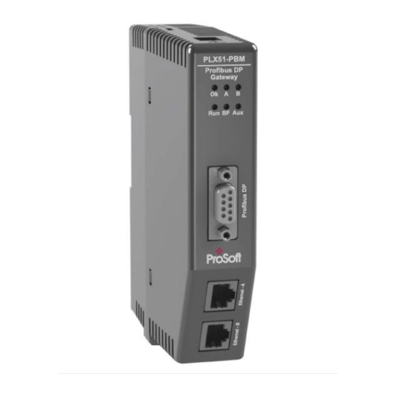
- Page 1 PLX51-PBM PROFIBUS DP Master/Slave to EtherNet/IP™ Gateway August 29, 2019 v1.0 USER MANUAL...
- Page 2 Page 2 of 162...
-
Page 3: Table Of Contents
Installing the Configuration Software ............... 17 Network Parameters ....................18 GSD File Management ....................22 Creating a New Project ....................25 PLX51-PBM Parameters .................... 27 General ....................... 27 PROFIBUS – Master Mode ................. 29 PROFIBUS – Slave Mode ..................32 Logix ........................ - Page 4 Slot Configuration - Modules ....................48 Data Points ..........................50 Slot Configuration – Logix Specific .................... 52 Start-up Parameters ................... 52 Adding PROFIBUS DP Devices – Slave Mode ............. 53 General ....................... 54 PROFIBUS Configuration ..................55 DPV1 ........................56 Slot Configuration ....................
- Page 5 Installation ....................... 107 Configuration ......................108 Operation ........................ 111 Diagnostics ........................115 LEDs ......................... 115 Module Status Monitoring ..................117 PLX51-PBM ....................... 118 General ............................ 119 Slave Status ..........................122 General Statistics ........................123 DPV1 Statistics ........................126 Live List ............................ 128 Discovered Nodes ........................
- Page 6 PROFIBUS master and slave ..................148 PROFIBUS master class 1 (DPM1) or class 2 (DPM2) ..........149 Cyclic communication ..................... 149 Acyclic communication.................... 150 Topology of PROFIBUS DP ..................150 PROFIBUS DP cable description ................151 PROFIBUS DP connector description............... 151 Appendix ........................
-
Page 7: Preface
Device Type Managers (DTMs). The PLX51-PBM slave feature can operate only as one or more PROFIBUS DPV0/DPV1 Slaves. This allows EtherNet/IP devices to exchange process, alarming, and diagnostic data with other PROFIBUS DP Master(s). - Page 8 Preface Figure 1.1 – PLX51-PBM Typical PROFIBUS Master Architecture Figure 1.2 – PLX51-PBM Typical PROFIBUS Slave Architecture Page 8 of 162...
-
Page 9: Features
The PLX51-PBM can be set to operate as either a PROFIBUS DP Master or Slave. The PLX51-PBM has two Ethernet ports allowing for either a Linear or Ring (Device Level Ring – DLR) Ethernet topology. The Ethernet ports can also be set up for port mirroring allowing for better fault analysis. -
Page 10: Architecture
Preface ARCHITECTURE The figure below provides an example of a typical network setup for a PLX51-PBM PROFIBUS Master architecture using an EtherNet/IP interface. Figure 1.3 – PLX51-PBM PROFIBUS Master to EtherNet/IP architecture The figure below provide an example of the typical network setup for a PLX51-PBM PROFIBUS Slave architecture using an EtherNet/IP interface. -
Page 11: Additional Information
Resource Link PLX50 Configuration www.prosoft-technology.com Utility Installation PLX51-PBM User Manual www.prosoft-technology.com PLX51-PBM Datasheet Table 1.1 - Additional Information SUPPORT Technical support is provided via the Web (in the form of user manuals, FAQ, datasheets etc.) to assist with installation, operation, and diagnostics. - Page 12 Page 12 of 162...
-
Page 13: Installation
Installation 2. INSTALLATION MODULE LAYOUT The PLX51-PBM has one RS485 PROFIBUS DP port as well as two Ethernet. The Ethernet cable must be wired according to industry standards, which can be found in the Additional Information section of this document. - Page 14 At the bottom of the PLX51-PBM module, there is one 3-way power connector. Figure 2.2 – PLX51-PBM Power connector The PLX51-PBM has an input voltage range of 10 to 36 VDC, applied to the module via the power connector. The power connector also provides an Earth connection for the PLX51- PBM.
-
Page 15: Module Mounting
Installation MODULE MOUNTING The PLX51-PBM provides a DIN rail clip to mount onto a 35mm DIN rail. Figure 2.4 - DIN rail specification The DIN rail clip is mounted at the back of the module as shown in the figure below. Use a flat screw driver to pull the clip downward. -
Page 16: Profibus Dp Port (Rs485)
Installation PROFIBUS DP PORT (RS485) The PROFIBUS DP port uses a female DB9 connector. This provides connection for the communication conductors, cable shielding, and +5Vdc output power. Figure 2.6 – PLX51-PBM PROFIBUS DP (RS485) DB9 connector Signal Description Not connected... -
Page 17: Setup
Setup 3. SETUP INSTALLING THE CONFIGURATION SOFTWARE All PLX51-PBM network setup and configuration is done in the ProSoft PLX50 Configuration Utility. This software can be downloaded from: www.prosoft-technology.com Figure 3.1. - ProSoft PLX50 Configuration Utility Environment Page 17 of 162... -
Page 18: Network Parameters
Setup NETWORK PARAMETERS The PLX51-PBM has DHCP (Dynamic Host Configuration Protocol) enabled as factory default. Thus, a DHCP server must be used to provide the module with the required network parameters (IP address, subnet mask, etc.). There are a number of DHCP utilities available, however it is recommended that the DHCP server in the PLX50 Configuration Utility is used. - Page 19 Figure 3.5. - Successful IP address assignment It is possible to force the PLX51-PBM back into DHCP mode by powering up the device with DIP switch 2 set to the On position. Page 19 of 162...
- Page 20 Setup A new IP address can then be assigned by repeating the previous steps. NOTE: It is important to return DIP switch 2 back to Off position, to avoid the module returning to a DHCP mode after the power is cycled again. In addition to the setting the IP address, a number of other network parameters can be set during the DHCP process.
- Page 21 Setup Right-clicking on a device, reveals the context menu, including the Port Configuration option. Figure 3.8. - Selecting Port Configuration The Ethernet port configuration parameters can be modified using the Ethernet Port Configuration window. Figure 3.9. - Port Configuration Alternatively, these parameters can be modified using Rockwell Automation’s RSLinx software.
-
Page 22: Gsd File Management
Each PROFIBUS device has a GSD file that is required to provide information needed to configure the device for data exchange. The PLX50 Configuration Utility manages the GSD library which is used for adding devices to the PLX51-PBM. 1 The GSD File Management Tool is opened by selecting GSD File Management under the Tool menu in the configuration utility. - Page 23 Setup 3 To add a GSD file, select the Add option under the GSD File menu. Figure 3.12 – GSD File Adding 4 Select the required GSD file and click O Figure 3.13 – Adding GSD File 5 Once the file has been selected, the GSD File Management tool adds the slave device to the device list and recompile the GSD catalog.
- Page 24 Setup A GSD catalog can be exported from another PLX50 Configuration Utility by exporting the GSD catalog from one PLX50 Configuration Utility, and importing it in another. This is done by selecting either Import or Export under the Catalog menu as shown below: Figure 3.14 –...
-
Page 25: Creating A New Project
Setup CREATING A NEW PROJECT 1 Before you configure the module, a new PLX50 Configuration Utility project must be created. Under the File menu, select New. Figure 3.15 - Creating a new project 2 A PLX50 Configuration Utility Design Tool project is created, showing the Project Explorer tree view. - Page 26 Setup 4 In the Add New Device window, the PLX51-PBM and click the O button. Figure 3.17 – PLX51-PBM 5 The device appears in the Project Explorer tree and its configuration window opened. The device configuration can be reopened by double-clicking the module in the Project Explorer tree, or right-clicking the module and selecting Configuration.
-
Page 27: Plx51-Pbm Parameters
Refer to the Additional Information section for documentation and installation links for ProSoft’s PLX50 Configuration Utility. ENERAL The PLX51-PBM General configuration is opened by either double-clicking on the module in the tree, or right-clicking the module and selecting Configuration. Figure 3.19 – PLX51-PBM General configuration... - Page 28 The PLX51-PBM can operate in one of three modes: Quiet This mode allows you to connect the PLX51-PBM to an active bus and run a DP packet capture. In this mode, the PLX51-PBM will not communicate on the DP Bus, but rather only listen.
-
Page 29: Profibus - Master Mode
The PROFIBUS configuration consists of the following parameters: Parameter Description Basic Settings PROFIBUS Station Address for the PLX51-PBM module. TS should be unique on the Station Address (TS) PROFIBUS network, it should also be less-than or equal to the HSA below: Min: 0... - Page 30 (DPV1, …). Min: 0 Max: 16777215 Slot Time (in tbits) is the maximum time the PLX51-PBM will wait, after the Slot Time (TSL) transmission of a request, for the reception of the first byte (Tchar) of an answer. (It allows detecting a timeout.) It can be increased when repeaters are used in the PROFIBUS network topology.
- Page 31 Setup Setup Time (in tbits) is the reaction time on an event. Calculation of TSET must Setup Time (TSET) respect the rule: Min: 1 Max: 494 PROFIBUS Cycle (in ms) (read/Write) field defines the cyclic time the master will PROFIBUS Cycle respect between two IO Data Exchange sequences.
-
Page 32: Profibus - Slave Mode
Setup PROFIBUS – S LAVE The PLX51-PBM PROFIBUS configuration is opened by either double-clicking on the module in the tree, or right-clicking the module and selecting Configuration. Then select the PROFIBUS tab. Figure 3.21 – PLX51-PBM PROFIBUS configuration – Slave mode... -
Page 33: Logix
OGIX This section is used when the Primary Interface is set to EtherNet/IP. The PLX51-PBM Logix configuration is opened by either double-clicking on the module in the tree, or right-clicking the module and selecting Configuration. Then select the Logix tab. - Page 34 Setup To browse to a controller path, select the B … button to open the Target Browser. ROWSE Then select a Logix controller and click Ok. The path updates automatically. Figure 3.23 – Target Browser – Selecting Logix controller Page 34 of 162...
-
Page 35: Advanced
Setup DVANCED The PLX51-PBM Advanced configuration is opened by either double-clicking on the module in the tree, or right-clicking the module and selecting Configuration. Then select the Advanced tab. Figure 3.24 – PLX51-PBM Advanced configuration The Advanced configuration consists of the following parameters:... -
Page 36: Module Download
Setup MODULE DOWNLOAD Once the PLX51-PBM configuration is complete, it must be downloaded to the module. The configured IP address of the module is used to connect to the module. 1 To initiate the download, right-click on the module and select the Download option. - Page 37 Setup 3 Within the PLX50 Configuration Utility environment, the module will be in the Online state, indicated by the green circle around the module icon. The module is now configured and will start operating immediately. Figure 3.27 - Module online Page 37 of 162...
-
Page 38: Device Discovery (Online) - Master Mode
Setup DEVICE DISCOVERY (ONLINE) – MASTER MODE Once online with the PLX51-PBM in the PLX50 Configuration Utility, you will be able to scan the PROFIBUS network for slave devices. NOTE: If the incorrect PROFIBUS parameters have been configured (e.g. BAUD rate) it will result in the PLX51-PBM not seeing any slave devices on the PROFIBUS network. - Page 39 Setup 3 If a device has been found not currently in the PLX51-PBM configured device list, you will be able to add the device from this window by right-clicking on the device and selecting Add Device. NOTE: The GSD file will need registered before a device can be added to the PLX51-PBM configuration.
-
Page 40: Device Station Address Change
Setup EVICE TATION DDRESS HANGE Certain devices can be set up to allow remotely changing of the station address. Devices with this option set general defaults to station address 126. 1 You can change the station address of a device (if the device is correctly set up) by right-clicking on the device in the Discovery list and selecting Change Station Address. -
Page 41: Adding Profibus Dp Devices - Master Mode
Add PROFIBUS Device. Figure 3.35 – Adding a PROFIBUS Field Device 2 Select the device to be added to the PLX51-PBM. This is done by selecting the device from the GSD File Selector and click O Figure 3.36 –... -
Page 42: General
Setup 3 Once the device has been added, the General Configuration page opens and the device is added at the first open PROFIBUS Station Address. Figure 3.37 – PROFIBUS Field Device Added ENERAL The Device Configuration is opened by either double-clicking on the slave device in the tree, or right-clicking the slave device and selecting Configuration. -
Page 43: Profibus Configuration
The minimum and default values are defined by the PLX51-PBM Default Watchdog setting in the PLX51-PBM PROFIBUS configuration. -
Page 44: Dpv1
Setup DPV1 The slave device DPV1 configuration is opened by either double-clicking on the slave device in the tree, or right-clicking the slave device and selecting Configuration. Then select the DPV1 tab. Figure 3.40 – DPV1 configuration parameters Page 44 of 162... - Page 45 This parameter specifies the maximum number of possible active alarms Alarm Mode for the device. This parameter forces the PLX51-PBM to use Service Access Point (SAP) 50 Alarm Ack uses SAP50 to acknowledge alarms. Enables specific alarms for the slave device to report.
-
Page 46: User Parameters
Setup ARAMETERS The User Parameters configuration is opened by either double-clicking on the slave device in the tree, or right-clicking the slave device and selecting Configuration. Then select the User Parameters tab. Figure 3.41 – Device User Parameter configuration parameters The User Parameters configuration consists of the device-specific user configuration. -
Page 47: Slot Configuration
Setup ONFIGURATION Each slave device can have multiple slots configured. A slot can be a placeholder for a process variable or a placeholder for a specific piece of hardware. In the example below, the added PROFIBUS slave device is an I/O adapter that can have multiple additional I/O modules, which will be represented as additional slots. -
Page 48: Slot Configuration - Modules
Setup 3 The module is added to the Slot Configuration. Figure 3.44 – Slot configuration – (Logix) SLOT CONFIGURATION - MODULES Each added module can consist of one or more Data Points. In the example below, the module has two Data Points; one Input and one Output. The description of each is based on the module name (from GSD file), but can be edited. - Page 49 Setup 2 The Module User Parameter Editor window opens. The parameters and their enumerated options are derived from the GSD file. Figure 3.47 – Device Slot configuration additional parameters 3 Once the slot parameters have been updated, click O . This updates the Extended User Parameters and return to the Slot Configuration page.
-
Page 50: Data Points
Setup DATA POINTS Formatting the modules data can be achieved by a combination of adding or removing Data Points and changing the Data Type of each. Data Points can be added by either right-clicking on the module and selecting Add Data Point or by clicking on the “+”... - Page 51 Setup Data Type Byte Length MUST be a multiple of: BOOL SINT DINT REAL Table 3.9 – Data Type – Byte Length Restrictions NOTE: It is critical that the configured Byte Length be a multiple of the base Data Type. NOTE: It is critical that the total sum of input and output bytes (of all the Data Points) match that required by the slave device.
-
Page 52: Slot Configuration - Logix Specific
Figure 3.52 – Start-up Parameters Example Once the slave device has been successfully parameterized and configured for Data Exchange, the PLX51-PBM updates one parameter at a time for each slave device. Page 52 of 162... -
Page 53: Adding Profibus Dp Devices - Slave Mode
Adding PROFIBUS devices to the PLX51-PBM is done by right-clicking on PROFIBUS Devices in the tree and selecting A PROFIBUS D EVICE Figure 3.53 – Adding a PROFIBUS Field Device When adding a PROFIBUS Device in Slave Mode, a static PLX51-PBM GSD file is automatically applied. Module GSD Filename PLX51-PBM PSFTS10FE.GSD... -
Page 54: General
Setup ENERAL The PLX51-PBM slave feature Device Configuration window is opened by either double- clicking on the slave device in the tree, or right-clicking the slave device and selecting Configuration. Figure 3.54 – General parameters The General configuration consists of the following parameters:... -
Page 55: Profibus Configuration
The PROFIBUS configuration consists of the following parameters: Parameter Description Node Address This is the station address configured for the added device. This is the address the PLX51-PBM will use to look for and configure the device for Data Exchange. TSDR Minimum Slave Interval Watchdog Enable... -
Page 56: Dpv1
Setup DPV1 The PLX51-PBM slave feature DPV1 configuration is opened by either double-clicking on the slave device in the tree, or right-clicking the slave device and selecting Configuration. Then select the DPV1 tab. Figure 3.56 – DPV1 parameters The DPV1 configuration consists of the following parameters:... -
Page 57: Slot Configuration
Setup ONFIGURATION The PLX51-PBM slave feature Slot configuration is the same as the Master Mode. See section 3.8.5. DPV1 O BJECTS The PLX51-PBM slave feature DPV1 Objects configuration window is opened by either double- clicking on the slave device in the tree, or right-clicking the slave device and selecting Configuration. - Page 58 Setup The Logix Tagname can be either entered manually or selected using the Logix Tag Browser by clicking on the Browse button (…) adjacent to the Tagname. NOTE: The Logix controller path must be correctly set for the tags to display in the browser.
-
Page 59: Dpv1 Alarms
Setup DPV1 A LARMS The PLX51-PBM slave feature DPV1 Alarms window is opened by either double-clicking on the slave device in the tree, or right-clicking the slave device and selecting Configuration. Then select the DPV1 Alarms tab. NOTE: The Size of the DPV1 Alarm must be greater than 4 or the alarm triggering will not execute. -
Page 60: Logix Configuration
EDS Hardware Installation Tool shortcut under the Tools menu in Studio 5000. Figure 3.60 - EDS Hardware Installation Utility After the EDS file has been registered, the PLX51-PBM can be added to the Logix I/O tree in Studio 5000. Page 60 of 162... - Page 61 Figure 3.61 – Adding a module 2 The Select Module Type window opens. To easily search for the module, use the Vendor filter to select only the ProSoft Technology modules as shown in the figure below. Figure 3.62 – Selecting the module...
- Page 62 Setup 3 Locate and select the PLX51-PBM module and click the C button. The New REATE Module window opens, where you must specify the Name and IP address to complete the instantiation. Figure 3.63 – Module instantiation 4 Once the instantiation is complete, the module appears in the Logix I/O tree.
-
Page 63: Generic Module Profile (Logix Pre-V21)
Figure 3.67 – Modified Logix Routine from PLX50 Configuration Utility for Generic Module Profile 1 When using Logix versions prior to version 21, the PLX51-PBM module must be added to the RSLogix 5000 I/O tree as a Generic Ethernet Module. This is achieved by right- clicking on the Ethernet Bridge in the RSLogix 5000 and selecting New Module. - Page 64 Setup 2 Enter the IP address, Input, Output, and Configuration parameters of the PLX51-PBM. The required connection parameters for the PLX51-PBM module are shown below: Connection Parameter Assembly Instance Size Input 500 (8-bit) Output 496 (8-bit) Configuration 0 (8-bit) Table 3.16 - RSLogix class 1 connection parameters for the PLX51-PBM module Figure 3.69 - General module properties for PLX51-PBM...
-
Page 65: Multi-Connection
Setup 4 Once the PLX51-PBM has been added to the RSLogix 5000 I/O tree, the Logix controller is ready to connect to the PLX51-PBM with a Class 1 connection. Figure 3.71 – RSLogix 5000 I/O module tree ULTI ONNECTION The PLX51-PBM supports up to four Class 1 (cyclic data exchange) connections. This allows for more field device connections per PLX51-PBM because more data can be exchanged between the Logix controller and the PLX51-PBM. - Page 66 Setup In Logix, you can increase/decrease the connection count using the EDS AOP (as shown below): Figure 3.73 – Logix EtherNet/IP Connection Count Page 66 of 162...
-
Page 67: Logix Mapping
The PLX50 Configuration Utility generates the required UDTs and Routines (based on the PLX51-PBM configuration) to map the required PROFIBUS Slave input and output data. 1 Generate the required Logix and UDTs by right-clicking on the module’s icon in the PLX50 Configuration Utility and selecting the G L5X option. - Page 68 Setup 3 This L5X file can now be imported in to the Studio 5000 project. Right-click on a suitable Program and select A , and then click I MPORT OUTINE Figure 3.76 – Importing the L5X file into Studio 5000 4 In the File Open window, select the L5X file and click O 5 Since the imported mapping routine is not a Main Routine, it will need to be called from the current Main Routine using a JSR.
- Page 69 Setup Figure 3.78 – Imported Logix Objects A number of PLX51 specific (UDT) tags are created as shown above. The Master Control tag is used to set the PROFIBUS Mode and to Enable the individual Slave Devices. Figure 3.79 – Master Control tag Page 69 of 162...
- Page 70 Setup The Master Status tag displays the status of the PROFIBUS Master, including arrays to show the LiveList, Data Exchange Active, Alarm, and Diagnostic pending status of each slave device. Figure 3.80 – Master Status tag There is also a tag created for each configured slave device. The structure of which comprises of the following: ...
-
Page 71: Operation
Operation 4. OPERATION LOGIX OPERATION The PLX51-PBM can exchange data with a Logix controller by establishing a Class 1 connection. PROFIBUS DP - M ASTER Once the PLX51-PBM and Logix controller have been correctly configured, the PLX51-PBM can exchange data with PROFIBUS slave devices. - Page 72 1 – PLX51-PBM has been successfully configured. 0 – PLX51-PBM is not configured. Owned Indicates if the PLX51-PBM is owned by a Logix Controller with a connection count similar to what has been configured in the PLX50 Configuration Utility. 1 – PLX51-PBM is connected.
- Page 73 1 – PROFIBUS fieldbus state is operational. 0 – PROFIBUS fieldbus state is not operational. SlaveMode When in Slave mode, the PLX51-PBM will emulate multiple PROFIBUS Slave devices. 1 – The PLX51-PBM is in PROFIBUS Slave Mode. 0 – The PLX51-PBM is not in PROFIBUS Slave Mode.
-
Page 74: Master Control
You will be able to see if there are any faults (e.g. configured device not found) by viewing the LEDs of the PLX51-PBM (see the Diagnostics section), by going online with the module in the PLX50 Configuration Utility and viewing the PLX51-PBM Master and Device Diagnostics, or by viewing the input assembly of the PLX51-PBM in Logix. - Page 75 1 – Online device Ident does not match configured device 0 – Online device and configured device ident match DisabledByOutputAssembly Indicates if the device has not been enabled for data exchange in the PLX51-PBM device enable control bits. Page 75 of 162...
- Page 76 0 – The mapping for the output data is correct 1 – There is a mapping mismatch in the output data SlaveClearOpMode When the PLX51-PBM is in Slave Mode; this indicates that the respective slave is in fieldbus CLEAR mode (received from the DP Master on the network).
-
Page 77: Dpv1 Explicit Messaging
Table 4.4 – Device Output tags DPV1 EXPLICIT MESSAGING The PLX51-PBM supports DPV1 Class 1 (MS1) and Class 2 (MS2) messaging, which can be used to read / write parameters in a slave device. The PLX51-PBM DPV1 communication is achieved... -
Page 78: Dpv1 Class 1 Messaging (Ms1)
DPV1 Class 1 messaging is achievable if the slave device is in data exchange mode (i.e. the device is configured and exchanging cyclic data with the PLX51-PBM). Only the DP Master exchanging data with the slave device can read and write parameters using DPV1 MS1. Below are the EtherNet/IP CIP message parameters, as well as the request and response data structures. - Page 79 Parameter Data Type Description Timeout DINT The amount of time (in milliseconds) the PLX51-PBM waits for a DPV1 response before timing out and responding to the EtherNet/IP request with a Timeout Status. Slave Address Byte The station number of the PROFIBUS device.
-
Page 80: Dpv1 Class 2 Messaging (Ms2)
Parameter Data Type Description Timeout DINT The amount of time (in milliseconds) the PLX51-PBM waits for a DPV1 response before timing out and responding to the EtherNet/IP request with a Timeout Status. Slave Address Byte The station number of the PROFIBUS device. - Page 81 Parameter Data Type Description Timeout DINT The amount of time (in milliseconds) the PLX51-PBM waits for a DPV1 response before timing out and responding to the EtherNet/IP request with a Timeout Status. Slave Address Byte The station number of the PROFIBUS device.
- Page 82 Operation Destination API Byte Destination SCL Byte Destination Net Address Byte[] Destination MAC Address Byte[] Table 4.12 – DPV1 Class 2 Initialize Request RESPONSE DATA: Parameter Data Type Description Status Byte This is the status of the DPV1 data exchange. See appendix for the definitions of the returned status.
- Page 83 Operation Service Code 0x4E (Hex) Class 0x432 (Hex) Instance Attribute Request Data Length Table 4.14 – DPV1 Class 2 Abort Message REQUEST DATA: Parameter Data Type Description Reserved DINT Connection Reference Byte Connection Reference Received from the DPV1 Class 2 Initialize Response.
- Page 84 Parameter Data Type Description Timeout DINT The amount of time (in milliseconds) the PLX51-PBM waits for a DPV1 response before timing out and responding to the EtherNet/IP request with a Timeout Status. Connection Reference Byte Connection Reference Received from the DPV1 Class 2 Initialize Response.
-
Page 85: Profibus Diagnostics
Table 4.22 – DPV1 Class 2 Write Response PROFIBUS DIAGNOSTICS The PLX51-PBM flags you when new diagnostics have been received. You can extract the diagnostics message from the PLX51-PBM by using EtherNet/IP unconnected messaging (UCMM) or Class 3 connected messaging. - Page 86 The PLX51-PBM will notify you of pending diagnostics as shown below. MASTER UDT In the PLX51-PBM status tags (see Logix Mapping section), the FieldDeviceDiagPending tag is an array of Boolean tags that each represent a node on the network. Below is a description of the tag.
- Page 87 Operation Read the slave device diagnostics that has been buffered in the PLX51-PBM. Read the slave device diagnostics that has been buffered in the PLX51-PBM and clear the Diagnostics Pending indication. Force the PLX51-PBM to send a PROFIBUS Diagnostic Request to the specific slave device and return the diagnostics data received.
-
Page 88: Global Control
REQUEST DATA: Parameter Data Type Description Timeout DINT The amount of time (in milliseconds) the PLX51-PBM waits for a response before timing out and responding to the EtherNet/IP request with a Timeout Status. Control Byte The Global Control action: Page 88 of 162... -
Page 89: Alarming
Table 4.31 – Global Control Response ALARMING The PLX51-PBM will flag you when a new alarm has been received. When a new alarm has been flagged by the PLX51-PBM, you can extract the alarm from the PLX51-PBM by using EtherNet/IP unconnected messaging (UCMM) or Class 3 connected messaging. - Page 90 The PLX51-PBM will notify you of a pending alarm as shown below. MASTER UDT In the PLX51-PBM status tags (see Logix Mapping section), the FieldDeviceAlarmPending is an array of Boolean tags each of which represents a node on the network. Below is a description of the tag.
-
Page 91: Profibus Dp - Slave
Parameter Data Type Description Timeout DINT The amount of time (in milliseconds) the PLX51-PBM waits for a DPV1 response before timing out and responding to the EtherNet/IP request with a Timeout Status. Slave Address Byte The station number of the PROFIBUS device. -
Page 92: General Status
1 – PLX51-PBM has been successfully configured. 0 – PLX51-PBM is not configured. Owned Indicates if the PLX51-PBM is owned by a Logix Controller with a connection count similar to what has been configured in the PLX50 Configuration Utility. 1 – PLX51-PBM is connected. - Page 93 1 – The PROFIBUS network is in Operation mode. 0 – The PROFIBUS network is not in Operation mode. SlaveMode When in Slave mode, the PLX51-PBM will emulate multiple PROFIBUS Slave devices. 1 – The PLX51-PBM is in Slave Mode.
-
Page 94: General Control
Table 4.37 – Logix General Status tags GENERAL CONTROL The PLX51-PBM Slave feature operates similar to Master mode, but each configured Slave is enabled by setting the correct enable bit in the Logix output assembly. Once the respective Page 94 of 162... - Page 95 Operation bit has been set in the DeviceEnable BOOL array, the PLX51-PBM becomes “alive” on the PROFIBUS network, and will start responding to a PROFIBUS DP Master. Figure 4.5 – General Control tags Description MasterControl This tag is used to set the state of the fieldbus network.
-
Page 96: Status And Dpv0 Data Exchange
The DPV0 data is exchanged with Logix using the Class 1 EtherNet/IP connection. The device- specific tag contains all the input and output data fields, as well as important control and status information. Figure 4.6 – PLX51-PBM Slave Device-Specific tag Description Status Online This bit indicates if the device is online on the PROFIBUS network. - Page 97 DisabledByOutputAssembly This bit indicates if the device has not been enabled for data exchange in the PLX51-PBM device enable control bits. 1 – Device has not been enabled for data exchange 0 – Device has been enabled for data exchange DeviceError This bit indicates an error with the device.
-
Page 98: Dpv1 Class 1 Messaging (Ms1)
Table 4.40 – Device Output tags DPV1 CLASS 1 MESSAGING (MS1) The PLX51-PBM Slave feature supports DPV1 Class 1 (MS1) messaging. See the DPV1 Objects in the PLX50 Configuration Utility Device Configuration section for more information Page 98 of 162... -
Page 99: Alarming
When the PROFIBUS Master sends a DPV1 read/write command for the configured slot and index, the PLX51-PBM accesses the configured Logix tag to provide the required data. The data to be written or read is extracted from the Logix SINT array. This array was configured in the DPV1 objects of the device configuration window. - Page 100 AlarmTrigger tag in the field device output assembly as shown below: Figure 4.8 – PLX51-PBM Slave Alarm Trigger 2 Once the alarm has been triggered, the PLX51-PBM reads the alarm data from the configured Logix tag and add it to the PROFIBUS diagnostics (which will then be read by the PROFIBUS Master).
-
Page 101: Explicit Messaging Utility
An example of the Alarm Data is shown below: Figure 4.10 –DPV1 Alarm Data Example EXPLICIT MESSAGING UTILITY The PLX50 Configuration Utility provides a utility to initiate explicit messages to the PROFIBUS devices via the PLX51-PBM. The messaging options include the following: Page 101 of 162... - Page 102 Operation DPV1 Class 1 Read DPV1 Class 1 Write DPV1 Class 2 Read DPV1 Class 2 Write Read Diagnostics Read Alarms 1 Right-click on a PROFIBUS device and select the E option. XPLICIT ESSAGING Figure 4.11 –...
-
Page 103: Firmware Upgrading
A button is selected, or the BORT utility is closed. Figure 4.12 – Explicit Messaging Utility FIRMWARE UPGRADING Using the PLX50 Configuration Utility, you can upgrade the PLX51-PBM firmware in the field. Page 103 of 162... - Page 104 2 In the Select a Device Flash File window, select the appropriate AFB binary file and click O Figure 4.14 - Select the AFB binary 3 In the Target Browser window, select the PLX51-PBM’s IP address and click O Page 104 of 162...
- Page 105 4 Once the firmware update is complete, the DeviceFlash option provides the details of the updated module. Figure 4.16 – PLX51-PBM successfully updated. NOTE: The PLX51-PBM firmware is digitally signed so you will only be able to flash the PLX51-PBM with authorized firmware. Page 105 of 162...
- Page 106 Page 106 of 162...
-
Page 107: Device Type Manager (Dtm)
Device Type Manager (DTM) 5. DEVICE TYPE MANAGER (DTM) The PLX51-PBM supports FDT / DTM technology, allowing you to configure any slave device using its DTM (Device Type Manager) in any standard FDT Frame (Field Device Tool). To use a device DTM with the PLX51-PBM, the ProSoft PLX51 DTM pack software must be installed. -
Page 108: Configuration
FDT frame. Typically, you select the DTM Catalogue or Device Catalogue, and select Refresh or rebuild. 1 After the catalogue has been updated, the PLX51-PBM can be added to a new project. 2 From the Add Device function, select the PLX51-PBM DTM and click O . - Page 109 4 The PLX51-PBM DTM’s configuration allows the CIP Path to the PLX51-PBM to be configured. This is typically the IP address of the PLX51-PBM. The path can either be entered manually or the Browse […] button can be used to open the Target Browser to select the PLX51-PBM.
- Page 110 Device Type Manager (DTM) 5 Once the PLX51-PBM DTM has been configured, the child Device DTMs can be added by right-clicking on the PLX51-PBM DTM icon and selecting A EVICE 6 Select the matching device DTM. Click O Figure 5.7 – Device DTM Selection 7 Once the child Device DTM has been added, a configuration window opens to set the Station Node Address.
-
Page 111: Operation
1 Once the FDT project is configured, the DTMs can be placed online by selecting the Online or Connect option. Figure 5.9 – DTM Connect 2 Once the PLX51-PBM DTM is online (connected), a number of diagnostic pages can be opened by selecting Measure Value. Figure 5.10 – Measured Value... - Page 112 Device Type Manager (DTM) 3 The General page provides basic status information for the PLX51-PBM module, including LED status, CPU status, etc. Figure 5.11 – PLX51-PBM DTM - General Status Page 4 The Live List page shows the state of the devices on the PROFIBUS network.
- Page 113 Device Type Manager (DTM) 5 The Slave Device DTM under the PLX51-PBM DTM can also be placed online by selecting the Online or Connect option. Figure 5.13 – Slave Device DTM Connect 6 Depending on the device DTM, a number of online parameters, diagnostics and measure variables is displayed.
- Page 114 Device Type Manager (DTM) Page 114 of 162...
-
Page 115: Diagnostics
Diagnostics 6. DIAGNOSTICS LEDS The module provides six LEDs for diagnostics purposes as shown below. Figure 6.1 - PLX51-PBM LEDs Description Flashing Green – The module has booted and is running correctly without any application configuration loaded. Solid Green – The module has booted and is running correctly with application configuration loaded. - Page 116 Diagnostics This LED indicates the PROFIBUS operating mode when in Master mode (Note that in Slave mode, this LED is N/A). Master Solid Red – The PROFIBUS network is in STOP mode. Flashing Green – The PROFIBUS network is in CLEAR mode. Solid Green –...
-
Page 117: Module Status Monitoring
Diagnostics MODULE STATUS MONITORING The PLX51-PBM provides a range of statistics that can assist with module operation, maintenance, and fault finding. The statistics can be accessed by the PLX50 Configuration Utility or using the web server in the module. To view the module’s status in the PLX50 Configuration Utility environment, the PLX51-PBM must be online. -
Page 118: Plx51-Pbm
Diagnostics PLX51-PBM The PLX51-PBM Status window is opened by either double-clicking on the Status item in the Project Explorer tree, or by right-clicking on the module and selecting Status. Figure 6.3 - Selecting PLX51-PBM online Status The status window contains multiple tabs to display the current status of the module. -
Page 119: General
Mode of operation of the module. The following states can be returned: Quiet This mode allows you to connect the PLX51-PBM to an active bus and run a DP packet capture. In this mode, the PLX51-PBM will not communicate on the DP Bus, but rather only listen. - Page 120 PLX51-PBM, the module will configure and exchange process data with each slave device. Note: In CLEAR mode, the PLX51-PBM will not send any output data to any slave device. Master Node (Master mode only) The PROFIBUS Node address of the local PLX51-PBM when in Master mode.
- Page 121 The status of the local NTP Client. Disabled The NTP time synchronization has been disabled. Locked NTP time synchronization has been enabled and the PLX51-PBM has locked onto the target time server. Not Locked NTP time synchronization has been enabled and the PLX51-PBM has not locked onto the target time server.
-
Page 122: Slave Status
Diagnostics SLAVE STATUS The Slave Status tab displays the following parameters: Figure 6.5 – PLX51-PBM Status monitoring – Slave Status Parameter Description BAUD Rate Current BAUD rate of the PROFIBUS Network. Auto-BAUD If the BAUD rate for the PROFIBUS Network will be automatically detected. -
Page 123: General Statistics
Diagnostics GENERAL STATISTICS The General Statistics tab displays the following general parameters: Figure 6.6 – PLX51-PBM Status monitoring – General Statistics Parameter Description Tx Packet Count The number of PROFIBUS packets transmitted. Rx Packet Count The number of PROFIBUS packets received. - Page 124 The minimum time (in microseconds) the PROFIBUS Cycle took to complete. Last Token Hold Time The time (in microseconds) the PLX51-PBM held the token in the last token rotation. Max Token Hold Time The maximum time (in microseconds) the PLX51-PBM held the token.
- Page 125 Diagnostics This occurs when the remote PROFIBUS device rejects a function request, e.g. if the device is not in the correct state, or if it does not support that function. A list of FDL errors is tabulated in chapter 9. Extract Alarm Success Count The number of alarms that have successfully been extracted from slave devices.
-
Page 126: Dpv1 Statistics
Diagnostics DPV1 STATISTICS The DPV1 Statistics tab displays the following general parameters: Figure 6.7 – PLX51-PBM Status monitoring – DPV1 Statistics Parameter Description DPV1 Class 1 Read Tx Count The number of PROFIBUS DPV1 Class 1 Read requests sent from the PLX51-PBM. - Page 127 PLX51-PBM. DPV1 Class 2 Read Rx Count The number of successful PROFIBUS DPV1 Class 2 Read responses received by the PLX51-PBM DPV1 Class 2 Read Err Count The number of failed PROFIBUS DPV1 Class 2 Read responses received by the PLX51-PBM.
-
Page 128: Live List
The Live List tab provides an overview of all slave devices and DP masters connected to the PROFIBUS network. Each station will be in one of six states. Figure 6.8 – PLX51-PBM Status monitoring – Live List DISCOVERED NODES The Discovered Nodes tab provides more detail regarding each station on the PROFIBUS network (when compared to the Live List). -
Page 129: Ethernet Clients
Figure 6.10 – PLX51-PBM Status monitoring – Ethernet Client Statistics TCP/ARP The TCP/ARP tab displays details of the internal Ethernet ARP and TCP lists of the PLX51- PBM. Figure 6.11 – PLX51-PBM Status monitoring – Ethernet TCP / ARP Statistics Page 129 of 162... -
Page 130: Device Status
Diagnostics EVICE TATUS The Device Status window of each PROFIBUS slave device connected to the PLX51-PBM is opened by right-clicking on the specific slave device icon in the PLX50 Configuration Utility tree, and selecting S TATUS Figure 6.12 - Selecting slave status The device status window contains multiple tabs to display the status of the specific slave device. -
Page 131: General - Master Mode
Online The slave device is online. Data Exchange Active The slave device is exchanging DPV0 process data with the PLX51-PBM. Disabled (PLC) The slave device has been disabled from DPV0 data exchange from the Logix controller using the PLX51-PBM output assembly. -
Page 132: Statistics
The device configured in the PLX50 Configuration Utility and the device online at the specific station address do not match. StationID Mismatch (PLC) The station address entered from the Logix controller using the PLX51-PBM output assembly does not match the station address of the configured slave device. CRC Mismatch (PLC) Indicates the mapping from the Logix controller does not match the configured mapping. - Page 133 Checksum Failed Packet Count The number of PROFIBUS packets that had a failed checksum. No Reply Count The number of PROFIBUS requests from the PLX51-PBM where the station did not respond. DPV1 Class 1 Read Tx Count The number of PROFIBUS DPV1 Class 1 Read requests sent from the PLX51-PBM to the specific device.
- Page 134 Diagnostics Set Slave Addr Tx Count The number of PROFIBUS Set Slave Address requests sent from the PLX51-PBM to the specific device. Set Slave Addr Rx Count The number of successful PROFIBUS Set Slave Address responses received from the specific device.
-
Page 135: Standard Diagnostics
Diagnostics STANDARD DIAGNOSTICS The Standard Diagnostics tab displays the following general parameters: Figure 6.15 – Device Status monitoring – Standard Diagnostics Parameter Description Class 1 Node The station address of the DP Master that configured the specific device for DPV0 communication. Ident The PNO Identification number of the device on the PROFIBUS network. -
Page 136: Extended Diagnostics
Diagnostics EXTENDED DIAGNOSTICS The Extended Diagnostics are decoded and displayed in a table form. The diagnostics are decoded using the pre-configured GSD file. Figure 6.16 – Device Status monitoring – Extended Diagnostics Page 136 of 162... -
Page 137: Profibus Packet Capture
PROFIBUS PACKET CAPTURE The PLX51-PBM allows you to capture the PROFIBUS traffic for analysis. 1 To invoke the capture of the module, right-click on the PLX51-PBM icon and double- click on the DP P item in the Project Explorer tree. - Page 138 Diagnostics 3 When the capture process is stopped, the PROFIBUS capture is presented as shown below. Figure 6.19 - PROFIBUS Packet Capture complete The captured PROFIBUS packets are tabulated as follows: Statistic Description Index The packet index incremented for each packet sent or received. Time The time is measured in microseconds (us) and is started at a fraction of a second and continued until the packet capture is done.
- Page 139 Diagnostics 4 The packet capture can be saved to a file for further analysis by selecting the S button on the toolbar. 5 Previously saved PROFIBUS Packet Capture files can be viewed by selecting the PROFIBUS P option in the Tools menu. ACKET APTURE IEWER...
-
Page 140: Module Event Log
Diagnostics MODULE EVENT LOG The PLX51-PBM logs various diagnostic records to an internal event log. These logs are stored in non-volatile memory and can be displayed using the PLX50 Configuration Utility or via the web interface. 1 To view them in the PLX50 Configuration Utility, double-click on the E... -
Page 141: Web Server
Diagnostics WEB SERVER The PLX51-PBM provides a web server for diagnostics. This allows for connectivity to the module without the use of the PLX50 Configuration Utility or Logix. NOTE: The web server is read-only and thus no parameters or configuration can be altered from the web interface. - Page 142 Page 142 of 162...
-
Page 143: Technical Specifications
Technical Specifications 7. TECHNICAL SPECIFICATIONS DIMENSIONS Below are the enclosure dimensions. All dimensions are in millimetres. Figure 7.1 – PLX51-PBM enclosure dimensions Page 143 of 162... -
Page 144: Electrical
Technical Specifications ELECTRICAL Specification Rating Power requirements Input: 10 to 36V DC Power consumption Maximum: 85mA @ 24V => 2.04W Connector 3-way terminal Conductors 24 to 18 AWG Enclosure rating IP20, NEMA/UL Open Type Temperature -20 to 70 °C Earth connection Yes, terminal based Emissions IEC61000-6-4... -
Page 145: Profibus Dp
Technical Specifications PROFIBUS DP Specification Rating Connector Female DB9 connector Conductor See PROFIBUS DP Section. DP Master Mode Support DPV0 Data Exchange DPV1 Class 1 Messaging DPV1 Class 2 Messaging DPV1 Alarming DP Slave Mode Support DPV0 Data Exchange DPV1 Class 1 Messaging DPV1 Alarming Isolated BAUD Rate supported... - Page 146 Page 146 of 162...
-
Page 147: Profibus Dp
PROFIBUS DP 8. PROFIBUS DP INTRODUCTION PROFIBUS is a vendor-independent, open fieldbus standard for a wide range of applications in manufacturing, process and building automation. Vendor independence and openness are guaranteed by the PROFIBUS standard EN 50 170. With PROFIBUS, devices of different manufacturers can communicate without special interface adjustments. -
Page 148: Profibus Master And Slave
PROFIBUS DP PROFIBUS PA PROFIBUS PA is designed especially for process automation. It permits sensors and actuators to be connected on one common bus line through a dedicated DP/PA gateway or link between the PROFIBUS DP and PROFIBUS PA networks, even in intrinsically-safe areas. PROFIBUS PA permits data communication and power over the bus using a 2-wire technology according to the international standard IEC 1158-2. -
Page 149: Profibus Master Class 1 (Dpm1) Or Class 2 (Dpm2)
PROFIBUS DP PROFIBUS MASTER CLASS 1 (DPM1) OR CLASS 2 (DPM2) PROFIBUS DP Master class 1 (DPM1) A class 1 master handles the normal communication or exchange of data with the slaves assigned to it. This is typically a PLC. It uses cyclic communication to exchange process data with its associated slaves. -
Page 150: Acyclic Communication
PROFIBUS DP ACYCLIC COMMUNICATION In addition to the cyclic data exchange, the PROFIBUS protocol has the option of acyclic communication. This service is not configured. There are 2 different communication channels possible between the requested master and the slave: o MS1 channel (MS1 connection): can only be established if cyclic data exchange is taking place between that master (DPM1) and the slave o MS2 channel (MS2 connection): is possible with several masters simultaneously, but the connection must be established explicitly by the master. -
Page 151: Profibus Dp Cable Description
1000 Table 9.3 – PROFIBUS DP cable length PROFIBUS DP CONNECTOR DESCRIPTION DB9 Pin Description DB9 Pin# DB9 Termination with PLX51-PBM Chassis ground Reserved Data+ / B In case of termination, connect this pin to Pin 8 (Data - / A) with 220 ohm resistor... - Page 152 Page 152 of 162...
-
Page 153: Appendix
Appendix 9. APPENDIX DPV1 RESPONSE STATUS (MASTER ONLY) DP Status Description Successful FDL error (see extended error code) DPV1 Error (see extended error code) Another command is already in progress for this slave / class 2 connection. Online state expected Invalid slave response Timeout passed Table 9.1 –... -
Page 154: Dpv1 Extended Status Codes (Master Only) - Dpv1 Error
Appendix DPV1 EXTENDED STATUS CODES (MASTER ONLY) – DPV1 ERROR DPV1 R RITE RROR DPV1 EXTENDED STATUS - BYTE 1 Value Description 0 to 127 Reserved DPV1 129 to 253 Reserved PROFIBUS FMS Table 9.3 – DP Extended Status Response codes (DPV1 Error) – Byte 1 DPV1 EXTENDED STATUS - BYTE 2 Bit 4 to 7 Value Bit 0 to 3 Value... -
Page 155: Dpv1 Abort
Appendix State conflict Access Denied Invalid range Invalid parameter Invalid type 10 to 15 User specific Resource Read constrain conflict Write constrain conflict Resource busy Resource unavailable 4 to 7 Reserved 8 to 15 User specific 13 to 15 User specific Table 9.4 –... -
Page 156: Dpv1 Extended Status - Byte 2 - Instance/Reason
DPV1 EXTENDED STATUS - BYTE 2 – INSTANCE/REASON Value Description Bit 6 to 7 Reserved 00 – FDL 01 – MSAC_C2 Bit 4 to 5 10 – User 11 – Reserved Bit 0 to 3 See EN 50170 Part 2 Table 9.6 –... -
Page 157: Support, Service & Warranty
Support, Service & Warranty 10. SUPPORT, SERVICE & WARRANTY CONTACTING TECHNICAL SUPPORT ProSoft Technology, Inc. is committed to providing the most efficient and effective support possible. Before calling, please gather the following information to assist in expediting this process: Product Version Number... - Page 158 Support, Service & Warranty Europe / Middle East / Africa Asia Pacific Regional Office Regional Office Phone: +33.(0)5.34.36.87.20 Phone: +60.3.2247.1898 europe@prosoft-technology.com asiapc@prosoft-technology.com Languages spoken: French, English Languages spoken: Bahasa, Chinese, English, Japanese, REGIONAL TECH SUPPORT Korean support.emea@prosoft-technology.com REGIONAL TECH SUPPORT support.ap@prosoft-technology.com Middle East &...
-
Page 159: Warranty Information
Languages spoken: Spanish, English REGIONAL TECH SUPPORT support.la@prosoft-technology.com WARRANTY INFORMATION For complete details regarding ProSoft Technology’s TERMS & CONDITIONS OF SALE, WARRANTY, SUPPORT, SERVICE AND RETURN MATERIAL AUTHORIZATION INSTRUCTIONS, please see the documents at: www.prosoft-technology.com/legal Documentation is subject to change without notice. - Page 160 Page 160 of 162...
-
Page 161: 11. Index
Discovery, 38, 40, 128 PLX51-PBM Advanced configuration, 35 Download, 36 PLX51-PBM general configuration, 27, 33 DPV1, 9, 30, 44, 45, 52, 56, 57, 58, 59, 78, 79, 80, 81, 82, PLX51-PBM parameters, 27 83, 84, 85, 87, 88, 91, 102, 120, 126, 127, 133, 147,... - Page 162 Index User Parameter, 46 TSDR, 30, 31, 43, 55 Watchdog, 31, 43, 55 web server, 117, 141 UDT, 86, 90 Page 162 of 162...
Need help?
Do you have a question about the PLX51-PBM and is the answer not in the manual?
Questions and answers