
Related Manuals for ProSoft Technology PLX51-PBM


Summary of Contents for ProSoft Technology PLX51-PBM
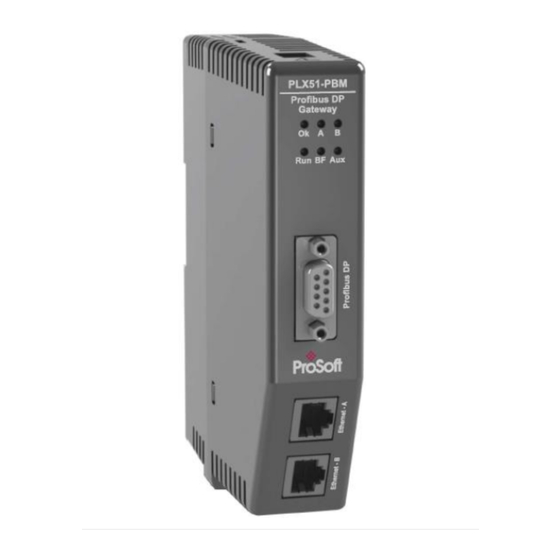
- Page 1 PLX51-PBM PROFIBUS DPV0/DPV1 Master or Slave to EtherNet/IP™ or Modbus ® Gateway June 23, 2021 USER MANUAL...
-
Page 2: Your Feedback Please
Neither ProSoft Technology nor any of its affiliates or subsidiaries shall be responsible or liable for misuse of the information contained herein. Information in this document including illustrations, specifications and dimensions may contain technical inaccuracies or typographical errors. -
Page 3: Table Of Contents
User Manual Contents Your Feedback Please ......................2 Content Disclaimer ........................ 2 Agency Approvals and Certifications ..................2 Preface Introduction to the PLX51-PBM ..............6 Features ....................... 7 1.2.1 PROFIBUS Master ..................8 1.2.2 PROFIBUS Slave ..................8 Architecture ....................9 Additional Information ................ - Page 4 Diagnostics LEDs ......................155 Module Status Monitoring ................ 157 8.2.1 PLX51-PBM Status Window ..............158 8.2.2 PLX51-PBM Master Mode Status ............159 8.2.3 PLX51-PBM Slave Mode Status .............. 167 8.2.4 PROFIBUS Slave Status ................. 173 PROFIBUS Packet Capture ..............180 Modbus Packet Capture ................
- Page 5 DPV1 Extended Status Codes (Master Only) – DPV1 Error ....193 11.3 11.3.1 DPV1 Read/Write Error ................193 11.3.2 DPV1 Abort ....................195 Support, Service & Warranty 12.1 Contacting Technical Support ..............196 12.2 Warranty Information ................196 ProSoft Technology, Inc. Page 5 of 196...
-
Page 6: Preface
This manual describes the installation, operation, and diagnostics of the ProSoft PLX51-PBM PROFIBUS DPV0/DPV1 Master/Slave module. The PLX51-PBM allows the user to interface PROFIBUS DP to EtherNet/IP or Modbus (RTU232, RTU485, TCP/IP). The PLX51-PBM can either operate as a PROFIBUS DPV0/DPV1 Master or multiple PROFIBUS DPV0/DPV1 Slaves. -
Page 7: Features
The PLX51-PBM will allow the user to interface PROFIBUS DPV0/DPV1 to either EtherNet/IP or Modbus. The PLX51-PBM can be set to operate as either a PROFIBUS DP Master or Slave. The PLX51-PBM, when configured as a Master can exchange up to 2 kilobytes of PROFIBUS device and status data (72 bytes are reserved for master status, and 8 bytes for each configured slave). -
Page 8: Profibus Master
The latter ensures alignment with the 16-bit data structure. The PLX51-PBM also provides DPV1 communication allowing the user to exchange DPV1 Class 1 and Class 2 data with each slave device. The PLX51-PBM Gateway DTM can be used to configure and parameterize each slave device using Device Type Manager (DTM) technology. -
Page 9: Architecture
The figures below provide an example of the typical network setup for a PROFIBUS Master architecture using either an EtherNet/IP or Modbus Interface. Figure 1.3 – PLX51-PBM PROFIBUS Master to EtherNet/IP architecture Figure 1.4 – PLX51-PBM PROFIBUS Master to Modbus (TCP/RTU232/RTU485) architecture ProSoft Technology, Inc. Page 9 of 196... - Page 10 The following figures provide an example of the typical network setup for a PROFIBUS Slave(s) architecture using either an EtherNet/IP or Modbus Interface. Figure 1.5 – PLX51-PBM PROFIBUS Slave to EtherNet/IP architecture Figure 1.6 – PLX51-PBM PROFIBUS Slave to Modbus (TCP/IP/RTU232/RTU485) architecture ProSoft Technology, Inc. Page 10 of 196...
-
Page 11: Additional Information
Table 1.2 - Additional Information Link Resource PLX50 Configuration www.prosoft-technology.com Utility Installation PLX51-PBM User Manual www.prosoft-technology.com PLX51-PBM Datasheet Support Technical support is provided via the Web (in the form of user manuals, FAQ, datasheets etc.) to assist with installation, operation, and diagnostics. -
Page 12: Installation
Installation Module Layout The PLX51-PBM has one RS485 PROFIBUS DP port as well as two Ethernet ports at the front of the module. The Ethernet cable must be wired according to industry standards which can be found in the additional information section of this document. - Page 13 PROFIBUS DPV0/DPV1 Master or Slave to EtherNet/IP™ or Modbus® Gateway User Manual The PLX51-PBM has an input voltage range of 10-36Vdc that needs to be applied to the module via the power connector. The power connector also provides an Earth connection for the PLX51-PBM.
- Page 14 This DIP Switch is used to lock the configuration from being overwritten by the PLX50 Configuration Utility. When set the PLX50 Configuration Utility will not be able to download to the PLX51-PBM module. DIP 4 When this DIP Switch is set at bootup it will force the module Ethernet IP address to 192.168.1.100 and network mask 255.255.255.0.
-
Page 15: Module Mounting
DIN rail. Once the module is mounted onto the DIN rail the clip must be pushed upwards to lock the module onto the DIN rail. Figure 2.6 - DIN rail mouting ProSoft Technology, Inc. Page 15 of 196... -
Page 16: Profibus Dp Port (Rs485)
PROFIBUS DP Port (RS485) The PROFIBUS DP port uses a female DB9 connector. This provides connection for the communication conductors, cable shielding and +5Vdc output power. Figure 2.7 – PLX51-PBM PROFIBUS DP (RS485) DB9 connector Table 2.2 – DB 9 Connector layout Signal... -
Page 17: Setup
DHCP utilities available, however it is recommended that the DHCP server in the PLX50 Configuration Utility be used. Within the PLX50 Configuration Utility environment, the DHCP server can be found under the Tools menu. Figure 3.2. - Selecting DHCP Server ProSoft Technology, Inc. Page 17 of 196... - Page 18 IP assignment, thereby disabling future DHCP requests. Once the IP address window has been accepted, the DHCP server will automatically assign the IP address to the module and then read the Identity object Product name from the device. ProSoft Technology, Inc. Page 18 of 196...
- Page 19 Once the DHCP process has been completed, the network settings can be set using the Ethernet Port Configuration via the Target Browser. The Target Browser can be accessed under the Tools menu. Figure 3.6. - Selecting the Target Browser ProSoft Technology, Inc. Page 19 of 196...
- Page 20 Figure 3.8. - Selecting Port Configuration All the relevant Ethernet port configuration parameters can be modified using the Port Configuration window. Figure 3.9. - Port Configuration Alternatively, these parameters can be modified using Rockwell Automation’s RSLinx software. ProSoft Technology, Inc. Page 20 of 196...
-
Page 21: Gsd File Management
Each PROFIBUS device has a GSD file that is required to provide information needed to configure the device for data exchange. The PLX50 Configuration Utility manages the GSD library which is used for adding devices to the PLX51-PBM. The GSD File Management Tool is opened by selecting GSD File Management under the Tool menu in the configuration utility. - Page 22 GSD catalog on one PLX50 Configuration Utility and importing it in another. This is done by selecting either Import or Export under the Catalog menu as shown below: Figure 3.14 – GSD Catalog importing ProSoft Technology, Inc. Page 22 of 196...
-
Page 23: Creating A New Project
A new device can now be added by selecting Add under the Device menu. Figure 3.16 - Adding a new device In the Add New Device window, select the PLX51-PBM and click the Ok button. Figure 3.17 – PLX51-PBM ProSoft Technology, Inc. - Page 24 The device configuration window can be reopened by either double clicking the module in the Project Explorer tree or right-clicking the module and selecting Configuration. Figure 3.18 – PLX51-PBM configuration ProSoft Technology, Inc. Page 24 of 196...
-
Page 25: Plx51-Pbm Parameters
The PLX51-PBM can operate in one of three modes: Quiet This mode allows the user to connect the PLX51-PBM to an active bus and run a DP packet capture. In this mode the PLX51-PBM will not communicate on the DP Bus but rather only listen. - Page 26 Modbus RTU Master – RS485 Modbus TCP/IP Slave Modbus RTU Slave – RS232 Modbus RTU Slave – RS485 EtherNet/IP Explicit Messaging (only when operating as a DP Slave) ProSoft Technology, Inc. Page 26 of 196...
-
Page 27: Modbus
The time (in milliseconds) the module will wait for a Modbus response (Modbus Master only) Enable Modbus Auxiliary When this is enabled the PLX51-PBM will be able to read from, and write to, Mapping multiple Modbus Slaves by using the Modbus Auxiliary Map tab. -
Page 28: Modbus Addressing
1. 3.5.3 Modbus Addressing The Modbus Addressing configuration is shown in the figure below. The PLX51-PBM Modbus Addressing configuration window is opened by either double clicking on the module in the tree or right-clicking the module and selecting Configuration. - Page 29 (PROFIBUS Master mode only) This will allow the user to enable or disable the retrieving of PROFIBUS Alarms from a field device using DPV1 Alarm HR Offset. IMPORTANT: The range of configured Modbus registers for each register type may not exceed 10,000. ProSoft Technology, Inc. Page 29 of 196...
-
Page 30: Profibus - Master Mode
3.5.4 PROFIBUS – Master Mode The PROFIBUS configuration (in Master Mode) is shown in the figure below. The PLX51-PBM PROFIBUS configuration window is opened by either double clicking on the module in the tree or right-clicking the module and selecting Configuration. - Page 31 Max: 16777215 Slot Time (TSL) Slot Time (in tbits) is the maximum time the PLX51-PBM will wait, after the transmission of a request, for the reception of the first byte (Tchar) of an answer. (It allows detecting a timeout.) It can be increased when repeaters are used in the PROFIBUS network topology.
- Page 32 Tsyn= 33 Tsm= 2 + 2* TSET + TQUI IMPORTANT: When the user changes the BAUD Rate all the PROFIBUS timing parameters will change to the default values for that specific BAUD Rate. ProSoft Technology, Inc. Page 32 of 196...
-
Page 33: Profibus - Slave Mode
3.5.5 PROFIBUS – Slave Mode The PROFIBUS configuration (in Slave Mode) is shown in the figure below. The PLX51-PBM PROFIBUS configuration window is opened by either double clicking on the module in the tree or right-clicking the module and selecting Configuration. -
Page 34: Logix
The Logix configuration is shown in the figure below. It is only relevant when the Primary Interface is set to EtherNet/IP. The PLX51-PBM Logix configuration window is opened by either double clicking on the module in the tree or right-clicking the module and selecting Configuration. -
Page 35: Advanced
PROFIBUS DPV0/DPV1 Master or Slave to EtherNet/IP™ or Modbus® Gateway User Manual 3.5.7 Advanced The Advanced configuration is shown in the figure below. The PLX51-PBM Advanced configuration window is opened by either double clicking on the module in the tree or right-clicking the module and selecting Configuration. -
Page 36: Modbus Auxiliary Map
Modbus tab and configured for Modbus Master. This will allow the user to read and/or write any internal PLX51-PBM Modbus Register to any Modbus Slave. Up to 20 Modbus Slaves can be connected and up to 200 mapped items can be configured. -
Page 37: Ethernet/Ip Devices
This tab is enabled when the Primary Interface selected is EtherNet/IP Explicit Messaging. IMPORTANT: EtherNet/IP Explicit Messaging is only allowed when the PLX51-PBM is operating as a Profibus Slave. The EtherNet/IP Devices configuration is shown in the figure below. Up to 5... -
Page 38: Ethernet/Ip Map
The required EtherNet/IP device can then be chosen by selecting it and clicking the Ok button, or by double-clicking on the target module. The amount of time the PLX51-PBM module will wait for a response from the Timeout target EtherNet/IP device. - Page 39 Similar to the Set function above, but the data to be written will be fixed (equal to the Static Value) parameter in this configuration window. This function will typically be used with the single Scan class which means the PLX51-PBM can be setup to write the fixed value only once when the target device communication has been established.
-
Page 40: Module Download
PROFIBUS DPV0/DPV1 Master or Slave to EtherNet/IP™ or Modbus® Gateway User Manual Module Download Once the PLX51-PBM configuration has been completed, it must be downloaded to the module. The configured IP address of the module will be used to connect to the module. -
Page 41: Device Discovery (Online) - Master Mode
User Manual Device Discovery (Online) – Master Mode Once online with the PLX51-PBM in the PLX50 Configuration Utility the user will be able to scan the PROFIBUS network for slave devices. IMPORTANT: If the incorrect PROFIBUS parameters has been configured (e.g. BAUD rate) it will result in the PLX51-PBM not seeing any slave devices on the PROFIBUS network. - Page 42 PROFIBUS DPV0/DPV1 Master or Slave to EtherNet/IP™ or Modbus® Gateway User Manual If a device has been found that is not currently in the PLX51-PBM configured device list the user will be able to add the device from this window by right-clicking on the device and selecting Add Device.
-
Page 43: Device Station Configuration Upload
The DPV0 communication configuration can be uploaded by right clicking on the discovery list and selecting Upload Configuration from All. Figure 3.39 – Selecting to upload the configuration from all Slaves. Figure 3.40 – DPV0 Communication Configuration successfully uploaded. ProSoft Technology, Inc. Page 43 of 196... -
Page 44: Device Station Address Change
IMPORTANT: Generally, the device will need to be in the correct state before it will accept a command to change its station address (i.e. must not be in data exchange state). ProSoft Technology, Inc. Page 44 of 196... -
Page 45: Discovery Report
This report summarizes the following device information found during discovery: Address, Identity Number, Status of configuration, Device name, GSD filename, and Upload Configuration status. Figure 3.43 – Accessing the Discovery Report Figure 3.44 – Discovery Report ProSoft Technology, Inc. Page 45 of 196... -
Page 46: Adding Profibus Dp Devices - Master Mode
Add PROFIBUS Device. Figure 3.45 – Adding a PROFIBUS Field Device The user will need to select the device to be added to the PLX51-PBM. This is done by selecting the device from the GSD File Selector and pressing Ok. -
Page 47: General
The General configuration consists of the following parameters: Description Parameter Instance Name The device instance name which will be used to create the Tag names and UDTs in Logix. Table 3.11 –Device General configuration parameters ProSoft Technology, Inc. Page 47 of 196... -
Page 48: Profibus Configuration
Parameter Node Address This is the station address configured for the added device. This is the address the PLX51-PBM will use to look for and configure the device for Data Exchange. TSDR This parameter is the minimum time that a PROFIBUS-DP slave must wait before it responds. - Page 49 Setup PROFIBUS DPV0/DPV1 Master or Slave to EtherNet/IP™ or Modbus® Gateway User Manual The minimum and default values are defined by the PLX51-PBM Default Watchdog setting in the PLX51-PBM PROFIBUS configuration. Group Membership Specifies which groups the slave belongs to. A slave can be in multiple groups at a time (from 1 through 8).
-
Page 50: Dpv1
By default, the field will be unchecked. Alarm Mode This parameter specifies the maximum number of possible active alarms for the device. ProSoft Technology, Inc. Page 50 of 196... -
Page 51: User Parameters
PROFIBUS DPV0/DPV1 Master or Slave to EtherNet/IP™ or Modbus® Gateway User Manual Alarm Ack uses SAP50 This will force the PLX51-PBM to use Service Access Point (SAP) 50 to acknowledge alarms. Alarm Enables Enables specific alarms for the slave device to report on if active. -
Page 52: Slot Configuration
The module will be added to the Slot configuration. The layout of the slot configuration differs slightly depending on whether Logix or Modbus has been selected as the Primary Interface. Figure 3.54 – Slot configuration – (Logix) ProSoft Technology, Inc. Page 52 of 196... - Page 53 These parameters can be accessed by either clicking on the Configure (…) button or by right-clicking on the Module and selecting the Configure Module option in the context menu. Figure 3.57 – Access Module Specific User Parameters ProSoft Technology, Inc. Page 53 of 196...
- Page 54 Data Points can be removed by either right-clicking on the module and selecting Delete Data Point or by clicking on the “X” button. Figure 3.59 – Adding / Removing Data Points NOTE: Each module must contain at least one Data Point. ProSoft Technology, Inc. Page 54 of 196...
- Page 55 IMPORTANT: It is critical that the total sum of input and output bytes (of all the Data Points) match that required by the slave device. Not adhering to this could cause unexpected results. NOTE: The DP (Byte) Offset for each the Data Point will be automatically calculated. ProSoft Technology, Inc. Page 55 of 196...
- Page 56 Modbus from Here option, after right-clicking on a particular mapped item. Once the assignment process is complete, all the mapped items below, and including, the selected item will be updated. Figure 3.63 – Slot configuration – Selecting Assign Modbus from Here option ProSoft Technology, Inc. Page 56 of 196...
- Page 57 The user can specify their preference using the Register Type and Discrete Type combo box options in the Modbus Reads section. Once the Ok button has been clicked, the Modbus Register Type and Modbus Offset for the selected, and subsequent items, will be updated. ProSoft Technology, Inc. Page 57 of 196...
-
Page 58: Start-Up Parameters
Figure 3.66 – Device Start-up Parameters Example Once the slave device has been successfully parameterized and configured for Data Exchange the PLX51-PBM will update one parameter at a time for each slave device. ProSoft Technology, Inc. Page 58 of 196... -
Page 59: Adding Profibus Dp Devices - Slave Mode
User Manual Adding PROFIBUS DP Devices – Slave Mode The user will need to add each PROFIBUS device to the PLX51-PBM, which can then be configured. This is done by right-clicking on the PROFIBUS Devices item in the tree and selecting Add PROFIBUS Device. -
Page 60: General
Configuration. Figure 3.69 – Device General configuration parameters When the module is emulating the legacy device, the PLX51-PBM General configuration parameters will appear as follows: Figure 3.70 – Device General configuration parameters (legacy device) The General configuration consists of the following parameters: Table 3.16 –Device General configuration parameters... -
Page 61: Profibus Configuration
Configuration. Figure 3.71 – Device PROFIBUS configuration parameters When the module is emulating the legacy device, the PLX51-PBM Profibus Configuration parameters will appear as follows: Figure 3.72 – Device PROFIBUS configuration parameters (legacy device) ProSoft Technology, Inc. - Page 62 This parameter will reformat the input and output Profibus DPV0 communication data. Below are the reformat options if the normal data format is AA BB CC DD: None BB AA DD CC BB AA CC DD AA BB ProSoft Technology, Inc. Page 62 of 196...
-
Page 63: Dpv1
Configuration. Figure 3.73 – Device DPV1 configuration parameters When the module is emulating the legacy device, the PLX51-PBM DPV1 configuration parameters will appear as follows: Figure 3.74 – Device DPV1 configuration parameters (legacy device) ProSoft Technology, Inc. -
Page 64: User Parameters
The DPV1 configuration consists of the following parameters: Table 3.18 – Device DPV1 configuration parameters Description Parameter Enable DPV1 Enables DPV1 capabilities for the PLX51-PBM in Slave Mode. Note: DPV1 capabilities are not available when the module is emulating the legacy device. Base 1ms... -
Page 65: Slot Configuration
To add a module, select the Add Module button. The module selection form will appear listing all the available modules from the GSD file. Figure 3.77 – Module Selection for the PLX51-PBM slave device selected ProSoft Technology, Inc. Page 65 of 196... - Page 66 DP Master: The Module Description filter can be used in conjunction with the wildcard character (“*”) to easily locate the required module. Once the required module has been selected press the Ok button. ProSoft Technology, Inc. Page 66 of 196...
- Page 67 Figure 3.80 – Slot configuration – (Explicit EtherNet/IP) When the module is emulating the legacy device, the slot configuration for Logix, Modbus, and Explicit EtherNet/IP will appear as follows: Figure 3.81 – Slot configuration – (Logix) (legacy device) ProSoft Technology, Inc. Page 67 of 196...
- Page 68 PLX51-PBM Setup PROFIBUS DPV0/DPV1 Master or Slave to EtherNet/IP™ or Modbus® Gateway User Manual Figure 3.82 – Slot configuration – (Modbus) (legacy device) Figure 3.83 – Slot configuration – (Explicit EtherNet/IP) (legacy device) ProSoft Technology, Inc. Page 68 of 196...
- Page 69 NOTE: Each module must contain at least one Data Point. After adding a new Data Point, the following should be configured: Description Data Point Type (Input, Output, None) Data Type Byte Length Figure 3.86 – Configuring Data Points ProSoft Technology, Inc. Page 69 of 196...
- Page 70 IMPORTANT: It is important that the Data Point Descriptions do not contain any illegal characters and are not duplicated within a device. Failing to do so will create errors when generating and importing the mapping L5X into Studio 5000. Figure 3.87 – Slot configuration – Logix Example ProSoft Technology, Inc. Page 70 of 196...
- Page 71 Modbus from Here option, after right-clicking on a particular mapped item. Once the assignment process is complete, all the mapped items below, and including, the selected item will be updated. Figure 3.89 – Slot configuration – Selecting Assign Modbus from Here option ProSoft Technology, Inc. Page 71 of 196...
- Page 72 IMPORTANT: It is important that the Data Point Register Type and Data Table Offset does not result in multiple Data Points overlapping. Such conflicts will cause unexpected results. IMPORTANT: The range of configured Data Table Offsets for each register type may not exceed 10,000. ProSoft Technology, Inc. Page 72 of 196...
-
Page 73: Dpv1 Objects
Read/Write Tagname The Logix Tagname where the data will be read / written. (Logix Only) Modbus Address The Modbus Holding Register Address where the data will be read / written. (Modbus Only) ProSoft Technology, Inc. Page 73 of 196... - Page 74 Browser. The Tag Browser can be launched by clicking on the Browse button (…) adjacent to the Tagname. NOTE: The list of Logix tags will not be available if the Logix controller path has not been correctly configured. Figure 3.94 – Device DPV1 Objects Tag Browsing ProSoft Technology, Inc. Page 74 of 196...
-
Page 75: Dpv1 Alarms
The Modbus Holding Register Address from where the alarm data will be read. (Modbus Only) Note: The DP Master connected to the PLX51-PBM (in slave mode) will be able to configure either of the following alarms: Diagnostic Alarm, Process Alarm, Pull Plug Alarm, Status Alarm, Update Alarm, Manufacturer Specific Alarm. -
Page 76: Logix Configuration
PROFIBUS DPV0/DPV1 Master or Slave to EtherNet/IP™ or Modbus® Gateway User Manual 3.10 Logix Configuration The PLX51-PBM can be easily integrated with Allen-Bradley Logix family of controllers. Integration with the Logix family in Studio5000 makes use of the EDS Add-On-Profile (AOP) or a Generic Module Profile. - Page 77 PROFIBUS DPV0/DPV1 Master or Slave to EtherNet/IP™ or Modbus® Gateway User Manual The module selection dialog will open. To find the module more easily, use the Vendor filter to select only the ProSoft Technology modules as shown in the figure below. Figure 3.99 – Selecting the module Locate and select the PLX51-PBM module and select the Create option.
- Page 78 The Module Defined Data Types will automatically be created during the instantiation process. These data types provide meaningful structures to the module data. An excerpt of the Input Image is shown in the following figure. Figure 3.102 – Module Defined Data Type ProSoft Technology, Inc. Page 78 of 196...
-
Page 79: Generic Module Profile (Logix Pre-V21)
Figure 3.105 - Add a Generic Ethernet Module in RSLogix 5000 The user must enter the IP address of the PLX51-PBM module that will be used. The assembly instance and size must also be added for the input, output, and configuration in the connection parameters section. - Page 80 PROFIBUS DPV0/DPV1 Master or Slave to EtherNet/IP™ or Modbus® Gateway User Manual The required connection parameters for the PLX51-PBM module are shown below: Table 3.22 - RSLogix class 1 connection parameters for the PLX51-PBM module Assembly Instance Size Connection Parameter...
- Page 81 Figure 3.107 - Connection module properties in RSLogix 5000 Once the module has been added to the RSLogix 5000 I/O tree the Logix controller will be ready to connect to the PLX51-PBM with a Class 1 connection. Figure 3.108 – RSLogix 5000 I/O module tree ProSoft Technology, Inc.
-
Page 82: Multi-Connection
Logix controller and the PLX51-PBM. IMPORTANT: This only applies when the user has implemented the PLX51-PBM into Logix using an EDS AOP. When using a Generic Module Profile in Logix (pre-Logix v21) the user will only be able to use 1 Logix Connection. -
Page 83: Logix Mapping
3.11 Logix Mapping The PLX50 Configuration Utility will generate the required UDTs and Routines (based on the PLX51-PBM configuration) to map the required PROFIBUS Slave input and output data. The user will need to generate the required Logix and UDTs by right-clicking on the module in the PLX50 Configuration Utility and selecting the Generate Logix L5X option. - Page 84 Multiple UDT (User-Defined Data Types) Multiple Controller Tags Since the imported mapping routine is not a Main Routine, it will need to be called from the current Main Routine. Figure 3.114 – Calling the mapping routine ProSoft Technology, Inc. Page 84 of 196...
- Page 85 A number of PLX51 specific (UDT) tags are created. The Master Control tag is used to set the PROFIBUS Mode and to Enable the individual Slave Devices. Figure 3.116 – Master Control tag ProSoft Technology, Inc. Page 85 of 196...
- Page 86 Input Data – As specified in the Input Data Points in the Slot configuration Output Control – Used to trigger alarms Output Data – As specified in the Output Data Points in the Slot configuration Figure 3.118 – Slave Device-Specific tag ProSoft Technology, Inc. Page 86 of 196...
-
Page 87: Importing The Add-On Instruction (Aoi)
A custom Add-On Instruction (AOI) is offered and recommended for use in the performance and monitoring of Class 3 messaging (connected or unconnected) with the PLX51-PBM. The AOI offered implements custom UDT’s, controller tags, and logic that instantiates the Ethernet/IP CIP messages to perform the following acyclic messaging services: ... - Page 88 Navigate to the location where the .L5X Add-On Instruction is saved. Select Open. Figure 3.102 – AOI File Selection The Import Configuration dialog box opens. It displays the controller tags to be created. Figure 3.103 – Controller Tags Imported ProSoft Technology, Inc. Page 88 of 196...
- Page 89 Logix project. 3.104 – Final Name of Module Click OK to perform the import. When complete, the Add-On Instruction rung appears in the routine. 3.105 – Add-On Instruction Rung ProSoft Technology, Inc. Page 89 of 196...
- Page 90 Path parameter. Click the module within ROWSE the I/O Configuration list, then click OK. 3.107 – Message Path Browser 10 Click OK in the Message Configuration window. Repeat for every CIP message provided within the AOI. ProSoft Technology, Inc. Page 90 of 196...
- Page 91 11 Navigate to the Controller Organizer window. Double click on the Controller Tags folder. 3.108 – Controller Tags Folder 12 The PLX51-PBM controller tags have been imported along with the Add-On Instruction. The PLX51PBM.CONTROL UDT contains the tags that control all of the acyclic messaging functions.
-
Page 92: Class 3 Messaging
3.12.1 Class 3 Messaging To perform Class 3 messaging with the AOI, you must first ensure that the PLX51-PBM is in the OPERATIONAL state and exchanging data with its configured nodes. NOTE: The slave device must support DPV1 messaging. The DPV1 Enable bit must be set in the user parameters of the slave device in the PLX50 Configuration Utility. - Page 93 Confirm the message was successfully sent by monitoring the MSGStatus tag. Figure 3.112 – DPV1 Class 1 Read Message Status The slave’s response to the acyclic message function is shown in the Response tags. Figure 3.113 – DPV1 Class 1 Read Response ProSoft Technology, Inc. Page 93 of 196...
-
Page 94: Dpv1 Class 2 Initialize
3.12.2 DPV1 Class 2 Initialize To perform a DPV1 Class 2 Read/Write, a DPV1 Class 2 Initialize message must first be sent to the DPV1 Slave to begin the communication connection. The PLX51-PBM Add-On Instruction (AOI) handles the source/destination address information of the Initialization request. - Page 95 The Destination Address Length (Dest_Addr_Len) to 2. The Ethernet/IP CIP Message Request length (MSGDPV1CLASS2INIT.REQ_LEN) to 40. Figure 3.115 – Implemented AOI Logic for Source Type = 1 and Destination Type = 0 ProSoft Technology, Inc. Page 95 of 196...
- Page 96 The Source Address Length (Source_Addr_Len) and the Destination Address Length (Dest_Addr_Len) both to 18. The Ethernet/IP CIP Message Request length (MSGDPV1CLASS2INIT.REQ_LEN) to 56. Figure 3.117 – Implemented AOI Logic for Source/Destination Type = 1 ProSoft Technology, Inc. Page 96 of 196...
-
Page 97: Sd Card
PROFIBUS DPV0/DPV1 Master or Slave to EtherNet/IP™ or Modbus® Gateway User Manual SD Card The PLX51-PBM supports an SD Card (see below) which can be used for disaster recovery. The SD Card can be pre-loaded with the required firmware and/or application configuration. -
Page 98: Firmware
IMPORTANT: The filename of the firmware file must not be changed. The specific module will use only the firmware that is valid (e.g. the PLX51-PBM will only use the PBM firmware file). IMPORTANT: If more than one firmware file, with different firmware revisions, of the same product is on the SD Card it can cause the module to constantly firmware upgrade the module. -
Page 99: Configuration
SD Card. Once the file has been created the user can copy this file into the root directory of the SD Card. Figure 4.4 – Configuration Export for SD Card ProSoft Technology, Inc. Page 99 of 196... - Page 100 IMPORTANT: The filename of the configuration file must not be changed. The specific module will use only the configuration that is valid (e.g. the PLX51-PBM will only use the PBM configuration file). IMPORTANT: If more than one configuration file, with different configuration signatures, of the same product is on the SD Card then only the last configuration will be used.
-
Page 101: Plx50Cu Upload
PC. IMPORTANT: All other configuration files in the SD Card root directory will be deleted when the upload is done. Figure 4.6 – Save Configuration to SD Card ProSoft Technology, Inc. Page 101 of 196... -
Page 102: Operation
User Manual Operation Logix Operation When the PLX51-PBM has been configured for Logix communication (by setting the Primary Interface to EtherNet/IP) it will exchange data with a Logix controller (e.g. ControlLogix or CompactLogix) by adding the PLX51-PBM module under an Ethernet bridge in the IO tree and establishing a Class 1 connection. - Page 103 PLX51-PBM, the module will configure and exchange process data with each slave device. NOTE: In CLEAR mode the PLX51-PBM will not send any output data to any slave device. 1 – PROFIBUS fieldbus state is CLEAR.
- Page 104 ‘0’ the device does not have any diagnostics pending. Bit 0 – Node 0 has diagnostics pending Bit 1 – Node 1 has diagnostics pending Bit 126 – Node 126 has diagnostics pending ProSoft Technology, Inc. Page 104 of 196...
- Page 105 PROFIBUS DPV0/DPV1 Master or Slave to EtherNet/IP™ or Modbus® Gateway User Manual Master Control The user will need to set the PROFIBUS Operating mode from the PLX51-PBM Logix output assembly in the Logix controller. Figure 5.2 – Master Control tags Table 5.2 –...
- Page 106 DisabledByOutputAssembly This bit indicates if the device has not been enabled for data exchange in the PLX51-PBM device enable control bits. 1 – Device has not been enabled for data exchange 0 – Device has been enabled for data exchange DeviceError This bit indicates an error with the device.
- Page 107 0 – The mapping for the output data is correct 1 – There is a mapping mismatch in the output data SlaveClearOpMode When the PLX51-PBM is in Slave Mode; this will indicate that the respective slave is in fieldbus CLEAR mode (received from the DP Master on the network).
- Page 108 DPV1 Explicit Messaging The PLX51-PBM supports DPV1 Class 1 (MS1) and Class 2 (MS2) messaging which can be used to read / write parameters in a slave device. The PLX51-PBM DPV1 communication is achieved by using EtherNet/IP unconnected messaging (UCMM) or Class 3 connected messaging.
- Page 109 Description Data Type Parameter Timeout Long The amount of time (in milliseconds) the PLX51-PBM waits for a DPV1 response before timing out and responding to the EtherNet/IP request with a Timeout Status. Slave Address Byte The station number of the PROFIBUS device.
- Page 110 Description Parameter Type Timeout Long The amount of time (in milliseconds) the PLX51-PBM waits for a DPV1 response before timing out and responding to the EtherNet/IP request with a Timeout Status. Slave Address Byte The station number of the PROFIBUS device.
- Page 111 Reason Code indicates the reason for the abort request. Refer to the PROFIBUS – DP Extensions to EN 50170 (DPV1) for more information regarding this parameter. Response Data: Table 5.16 – DPV1 Class 2 Abort Response Data Type Description Parameter None ProSoft Technology, Inc. Page 111 of 196...
- Page 112 Description Data Type Parameter Timeout Long The amount of time (in milliseconds) the PLX51-PBM waits for a DPV1 response before timing out and responding to the EtherNet/IP request with a Timeout Status. Connection Reference Byte Connection Reference Received from the DPV1 Class 2 Initialize Response.
- Page 113 Description Data Type Parameter Timeout Long The amount of time (in milliseconds) the PLX51-PBM waits for a DPV1 response before timing out and responding to the EtherNet/IP request with a Timeout Status. Connection Reference Byte Connection Reference Received from the DPV1 Class 2 Initialize Response.
- Page 114 The PLX51-PBM will notify the user of pending diagnostics as shown below. Master UDT In the Status part of the PLX51-PBM tags (see Logix Mapping section) there is a tag FieldDeviceDiagPending. This is an array of Boolean tags each of which represents a node on the network.
- Page 115 Mode Read the slave device diagnostics that has been buffered in the PLX51-PBM. Read the slave device diagnostics that has been buffered in the PLX51-PBM and clear the Diagnostics Pending indication. Force the PLX51-PBM to send a PROFIBUS Diagnostic Request to the specific slave device and return the diagnostics data received.
- Page 116 Table 5.30 – Global Control Request Data Type Description Parameter Timeout Long The amount of time (in milliseconds) the PLX51-PBM waits for a response before timing out and responding to the EtherNet/IP request with a Timeout Status. Control Byte The Global Control action:...
- Page 117 User Manual Alarming The PLX51-PBM will flag to the user when a new alarm has been received. When a new alarm has been flagged by the PLX51-PBM the user can extract the alarm from the PLX51-PBM by using EtherNet/IP unconnected messaging (UCMM) or Class 3 connected messaging.
- Page 118 Data Type Description Parameter Timeout Long The amount of time (in milliseconds) the PLX51-PBM waits for a DPV1 response before timing out and responding to the EtherNet/IP request with a Timeout Status. Slave Address Byte The station number of the PROFIBUS device.
-
Page 119: Profibus Dp - Slave
1 – PLX51-PBM has been successfully configured. 0 – PLX51-PBM is not configured. Owned Indicates if the PLX51-PBM is owned by a Logix Controller with a connection count similar to what has been configured in PLX50CU. 1 – PLX51-PBM is connected. - Page 120 PROFIBUS DPV0/DPV1 Master or Slave to EtherNet/IP™ or Modbus® Gateway User Manual 1 – The PLX51-PBM is in Slave Mode. 0 – The PLX51-PBM is not in Slave Mode. ConfigCRC The signature of the configuration currently executing on the module.
- Page 121 User Manual General Control The PLX51-PBM in Slave mode will operate similar to when in Master mode, but each configured Slave will be enabled by setting the correct enable bit in either the Logix output assembly. Once the respective bit has been set in the DeviceEnable BOOL array the PLX51-PBM will become “alive”...
- Page 122 The DPV0 data is exchanged with Logix using the Class 1 EtherNet/IP connection. The device-specific tag contains all the input and output data fields as well as important control and status information. Figure 5.6 – PLX51-PBM Slave Device-Specific tag Table 5.39 – Device Input tags Description...
- Page 123 0 – The mapping for the output data is correct. 1 – There is a mapping mismatch in the output data. SlaveClearOpMode When the PLX51-PBM is in Slave Mode; this will indicate that the respective slave is in fieldbus CLEAR mode (received from the DP Master on the network).
- Page 124 When the PROFIBUS Master sends a DPV1 read/write command for the configured slot and index, the PLX51-PBM will access the configured Logix tag to provide the required data. The data that will be written or read will be extracted from the Logix SINT array configured in the DPV1 objects of the device configuration window.
- Page 125 Figure 5.8 – PLX51-PBM Slave Alarm Trigger Once the alarm has been triggered the PLX51-PBM will read the alarm data from the configured Logix tag and add it to the PROFIBUS diagnostics (which will then be read by the PROFIBUS Master).
- Page 126 3 - One incident disappeared, others remain Refer to the PROFIBUS Specification EN Alarm data Alarm Length 50170 for information regarding the diagnostics. An example of the Alarm Data is shown below: Figure 5.10 –DPV1 Alarm Data Example ProSoft Technology, Inc. Page 126 of 196...
- Page 127 1 – Fault occurred and slot it not ok Alarm Specifier (Bit 0 to 1) 2 – Fault disappeared, and slot is ok 3 – One fault disappeared, and slot is not ok ProSoft Technology, Inc. Page 127 of 196...
-
Page 128: Modbus Operation
NOTE: When configured as a Modbus Slave the Modbus Master device will need to read and write all required data from the configured Modbus address ranges. When configured as a Modbus Master the PLX51-PBM will automatically update the required Modbus registers in the configured remote target. 5.2.1 PROFIBUS DP - Master Once the PLX51-PBM and Modbus device have been correctly configured, the PLX51-PBM will start exchanging data with PROFIBUS slave devices. - Page 129 Table 5.45 – Modbus Communication Status Description HR Offset Modbus Communication Status when operating as a Modbus Slave Bit 0 – PLX51-PBM Modbus Slave Communication Status 1 – Modbus Communication Ok 0 – Modbus Communication Failed Modbus Communication Status when operating as a Modbus Master Bit 0 –...
- Page 130 Once the transaction is complete the response part of the Holding Registers will be updated. NOTE: The user will need to toggle the trigger Holding Register from 0 to 1 before the transaction will begin. ProSoft Technology, Inc. Page 130 of 196...
- Page 131 This is the status of the DPV1 data exchange. See appendix Status for the definitions of the returned status. Reserved Data Size The size of the data to follow. Data The response data ProSoft Technology, Inc. Page 131 of 196...
- Page 132 Slave Address Target PROFIBUS Slave node address 0 – Read Diagnostic Buffer stored in the PLX51-PBM 1 – Read Diagnostic Buffer stored in the PLX51-PBM and Mode Clear the Diagnostics Pending bit Table 5.49 – Modbus DPV0 Diagnostic Response Message Holding Register Format...
- Page 133 Alarm Request Register Offset Bit 0 – Trigger Message Send Trigger The time in Milliseconds if no response has been received Timeout before the transaction times out Slave Address Target PROFIBUS Slave node address ProSoft Technology, Inc. Page 133 of 196...
- Page 134 The Modbus Auxiliary Map can be used to read or write Modbus data from the local PLX51-PBM to a remote Modbus Slave. This will be enabled when Enable Modbus Auxiliary Mapping has been enabled in the Modbus tab and configured for Modbus Master.
-
Page 135: Profibus Dp - Slave
User Manual 5.2.2 PROFIBUS DP - Slave The PLX51-PBM in Slave mode will operate similar to when in Master mode, but each configured Slave will be enabled by setting the correct enable bit in the Device Control Register. Once the respective bit has been set in the Device Control Register the PLX51-PBM Slave will become “alive”... - Page 136 Table 5.54 – Modbus Communication Status Description HR Offset Modbus Communication Status when operating as a Modbus Slave Bit 0 – PLX51-PBM Modbus Slave Communication Status 1 – Modbus Communication Ok 0 – Modbus Communication Failed Modbus Communication Status when operating as a Modbus Master Bit 0 –...
- Page 137 PLX51-PBM will use the data located at the configured Modbus Address. NOTE: If the PLX51-PBM has been setup as a Modbus Master then the data will be read or written to the specific Modbus HR address in the target device when the DPV1 Message request is received on the PROFIBUS network.
- Page 138 Modbus Holding address to provide the required data for the specific alarm. NOTE: The PLX51-PBM can only allow one alarm to be triggered at a time. To trigger an alarm notification for the PROFIBUS Master the user will need to toggle...
- Page 139 1 – Incident appeared 2 – Incident disappeared and slot is ok 3 - One incident disappeared, others remain Refer to the PROFIBUS Specification EN Alarm data Alarm Length 50170 for information regarding the diagnostics. ProSoft Technology, Inc. Page 139 of 196...
-
Page 140: Ethernet/Ip Explicit Messaging Operation
DP Slaves. Each EtherNet/IP device configured can also provide communication status which can be mapped to DPV0 data to inform the DP Master that the PLX51-PBM (in slave mode) has lost communication with a specific EtherNet/IP device. The user will need to enter the location in the Data Table where the communication status for the device can be found (as shown below). -
Page 141: Explicit Messaging Utility
PROFIBUS DPV0/DPV1 Master or Slave to EtherNet/IP™ or Modbus® Gateway User Manual Explicit Messaging Utility For PLX51-PBM Master mode only, the PLX50 Configuration Utility provides a utility to initiate explicit messages to the PROFIBUS devices. The messaging options include the following: ... - Page 142 PLX51-PBM Operation PROFIBUS DPV0/DPV1 Master or Slave to EtherNet/IP™ or Modbus® Gateway User Manual Figure 5.20 – Explicit Messaging Utility ProSoft Technology, Inc. Page 142 of 196...
-
Page 143: Firmware Upgrade
PROFIBUS DPV0/DPV1 Master or Slave to EtherNet/IP™ or Modbus® Gateway User Manual Firmware Upgrade The PLX51-PBM allows the user to upgrade the module firmware in the field. If the firmware needs to be updated the user will need to use the PLX50 Configuration Utility to update it. - Page 144 Once the module is done upgrading the firmware the Device Flash tool will provide the user with the details of the updated module. Figure 5.24 – PLX51-PBM successfully updated. IMPORTANT: The PLX51-PBM firmware is digitally signed so the user will only be able to flash the PLX51-PBM with authorized firmware. ProSoft Technology, Inc.
-
Page 145: Migrating Legacy Pcb Projects
Before importing a PCB application, ensure that all the necessary GSD files have first been registered in the PLX50 Configuration Utility’s GSD Manager. The PCB import requires a PLX51-PBM project with no existing slave devices configured. Open the ProSoft Configuration Builder (PCB) software and open the existing PROFIBUS project. - Page 146 Export Master Config button will then be enabled. Figure 6.3 – PCB Export Master Configuration The generated export (XML) file can then be saved. Figure 6.4 – PCB – Save Export XML File ProSoft Technology, Inc. Page 146 of 196...
- Page 147 Migrating Legacy PCB Projects PROFIBUS DPV0/DPV1 Master or Slave to EtherNet/IP™ or Modbus® Gateway User Manual In the PLX50 Configuration Utility, right-click on the PLX51-PBM module and select the Import Legacy PCB Configuration option. Figure 6.5 – Import Legacy PCB Configuration After the import is complete, an Import Report summary will be shown, and may indicate any issues encountered during the import process.
-
Page 148: Device Type Manager (Dtm)
The PLX51-PBM supports FDT / DTM technology, allowing the user to configure any slave device using its DTM (Device Type Manager) in any standard FDT Frame (Field Device Tool). To use a device DTM with the PLX51-PBM, the ProSoft PLX51 DTM pack will first need to be installed. -
Page 149: Configuration
FDT frame. Typically, one selects the DTM Catalogue or Device Catalogue and select Refresh or rebuild. After the catalogue has been updated, the PLX51-PBM device can then be added to a new project. This involves selecting the Add Device function and then selecting the PLX51-PBM DTM. - Page 150 After instantiating the PLX51-PBM DTM, select the Parameter option. Figure 7.4 – Select Parameter option The PLX51-PBM DTM’s configuration allows the CIP Path to the PLX51-PBM to be configured. This is typically just the IP address of the PLX51-PBM. Figure 7.5 – PLX51-PBM CIP Path The path can either be entered manually or the Browse button can be used to open the Target Browser, and then the PLX51-PBM can be selected.
- Page 151 PROFIBUS DPV0/DPV1 Master or Slave to EtherNet/IP™ or Modbus® Gateway User Manual Once the PLX51-PBM DTM has been configured, the child Device DTMs can be added by right-clicking on the PLX51-PBM DTM and selecting Add Device. The user can then select the matching device DTM.
-
Page 152: Operation
After the FDT project has been configured, the DTMs can be place online by selecting the Online or Connect option. Figure 7.9 – DTM Connect Once the PLX51-PBM DTM is online (connected) a number of diagnostic pages can be opened by selecting the Measure Value. Figure 7.10 – Measured Value ProSoft Technology, Inc. - Page 153 Device Type Manager (DTM) PROFIBUS DPV0/DPV1 Master or Slave to EtherNet/IP™ or Modbus® Gateway User Manual The General page provides basic status information for the PLX51-PBM module, including LED status and CPU status etc. Figure 7.11 – PLX51-PBM DTM - General Status Page The Live List page shows the state of the devices on the PROFIBUS network.
- Page 154 Device Type Manager (DTM) PROFIBUS DPV0/DPV1 Master or Slave to EtherNet/IP™ or Modbus® Gateway User Manual Slave Device DTM under the PLX51-PBM DTM can also be brought online by selecting the Online or Connect option. Figure 7.13 – Slave Device DTM Connect Depending on the device DTM, a number of online parameters, diagnostics and measure variables can be displayed.
-
Page 155: Diagnostics
LEDs The module provides six LEDs for diagnostics purposes as shown below. A description of each LED is given in the table below. Figure 8.1 - PLX51-PBM LEDs Table 8.1 - Module LED operation Description The module LED will provide information regarding the system-level operation of the module. - Page 156 EtherNet/IP, Modbus RTU, or Modbus TCP). Thus, every time a valid packet is received from the Primary Interface the LED will toggle green. The LED will toggle red if a corrupted packet was received (e.g. failed checksum when using RS232 or RS485). ProSoft Technology, Inc. Page 156 of 196...
-
Page 157: Module Status Monitoring
PLX50 Configuration Utility or using the web server in the module. To view the module’s status in the PLX50 Configuration Utility environment, the PLX51-PBM must be online. If the module is not already Online (following a recent configuration download), then right-click on the module and select the Go Online option. -
Page 158: Plx51-Pbm Status Window
PROFIBUS DPV0/DPV1 Master or Slave to EtherNet/IP™ or Modbus® Gateway User Manual 8.2.1 PLX51-PBM Status Window The Status monitoring window of the PLX51-PBM can be opened by either double- clicking on the Status item in the Project Explorer tree, or by right-clicking on the module and selecting Status. -
Page 159: Plx51-Pbm Master Mode Status
This is the mode of operation of the module. The following states can be returned: Quiet: This mode allows the user to connect the PLX51-PBM to an active bus and run a DP packet capture. In this mode the PLX51-PBM will not communicate on the DP Bus but rather only listen. - Page 160 Diagnostics PROFIBUS DPV0/DPV1 Master or Slave to EtherNet/IP™ or Modbus® Gateway User Manual NOTE: In CLEAR mode the PLX51-PBM will not send any output data to any slave device. Master Node The PROFIBUS Node address of the local PLX51-PBM when in Master mode.
- Page 161 PROFIBUS DPV0/DPV1 Master or Slave to EtherNet/IP™ or Modbus® Gateway User Manual General Statistics The General Statistics (PLX51-PBM Master mode only) tab displays the following general parameters: Figure 8.5 – PLX51-PBM (Master Mode) Status monitoring – General Statistics Table 8.3 - Parameters displayed in the Status Monitoring – General Statistics Tab...
- Page 162 The number of times the PLX51-PBM has determined that there are no other DP Masters on the PROFIBUS network. Duplicate Station Detect Count The number of times the PLX51-PBM has detected that there is another station on the network with the same station address as the local PLX51-PBM.
- Page 163 PROFIBUS DPV0/DPV1 Master or Slave to EtherNet/IP™ or Modbus® Gateway User Manual DPV1 Statistics The DPV1 Statistics (PLX51-PBM Master mode only) tab displays the following general parameters: Figure 8.6 – PLX51-PBM (Master Mode) Status monitoring – DPV1 Statistics Table 8.4 - Parameters displayed in the Status Monitoring – DPV1 Statistics Tab...
- Page 164 PLX51-PBM. Live List The Live List tab in the PLX51-PBM (Master mode only) status monitoring provides the user with an overview of all slave devices and DP masters connected to the PROFIBUS network. Each station will be in one of six states that are provided in the Live List page.
- Page 165 PROFIBUS DPV0/DPV1 Master or Slave to EtherNet/IP™ or Modbus® Gateway User Manual Modbus Statistics The Modbus Statistics tab displays the statistics associated with the Modbus communication and mapping. Figure 8.9 – PLX51-PBM Master mode status monitoring – Modbus Statistics Table 8.5 – Modbus statistics Description Statistic Tx Packet Count The number of Modbus packets sent by the module.
- Page 166 Figure 8.10 – PLX51-PBM Master mode status monitoring – Modbus Devices Ethernet Clients The Ethernet Clients tab displays details of the Ethernet and EtherNet/IP clients connected to the PLX51-PBM. Figure 8.11 – PLX51-PBM (Master mode) status monitoring – Ethernet Client Statistics ProSoft Technology, Inc. Page 166 of 196...
-
Page 167: Plx51-Pbm Slave Mode Status
TCP/ARP The TCP/ARP tab displays details of the internal Ethernet ARP and TCP lists of the PLX51-PBM. Figure 8.12 – PLX51-PBM (Master mode) status monitoring – Ethernet TCP / ARP Statistics 8.2.3 PLX51-PBM Slave Mode Status General The General tab displays the following general parameters. For more information, please see page 159. - Page 168 PROFIBUS DPV0/DPV1 Master or Slave to EtherNet/IP™ or Modbus® Gateway User Manual Slave Status The PLX51-PBM Slave mode diagnostics tab displays the following parameters. Figure 8.14 – PLX51-PBM (Slave Mode) Status monitoring Table 8.6 - Parameters displayed in the Status Monitoring – Slave Status Tab...
- Page 169 The Modbus Statistics tab displays the statistics associated with the Modbus communication and mapping. For more information, please see page 165. Figure 8.15 – PLX51-PBM Slave mode status monitoring – Modbus Statistics Modbus Devices The Modbus Devices tab displays the active Modbus Client/Server devices the module is communicating with.
- Page 170 EtherNet/IP target devices when the Primary Interface has been set to EtherNet/IP Explicit Messaging. Figure 8.17 – PLX51-PBM Slave mode status monitoring – EtherNet/IP Explicit Statistics Table 8.7 - Parameters displayed in the Status Monitoring – EtherNet/IP Explicit Statistics Description...
- Page 171 Messaging and the current communication status. Green being online and exchanging data, Red indicating that the target device is offline. Figure 8.18 – PLX51-PBM Slave mode status monitoring – EtherNet/IP Devices Explicit Map This shows all the mapped EtherNet/IP explicit messaged used for Explicit EtherNet/IP Messaging.
- Page 172 Figure 8.20 – PLX51-PBM (Slave mode) status monitoring – Ethernet Client Statistics TCP/ARP The TCP/ARP tab displays details of the internal Ethernet ARP and TCP lists of the PLX51-PBM. Figure 8.21 – PLX51-PBM (Slave mode) status monitoring – Ethernet TCP / ARP Statistics ProSoft Technology, Inc. Page 172 of 196...
-
Page 173: Profibus Slave Status
8.2.4 PROFIBUS Slave Status The Status monitoring window of each PROFIBUS slave device connected to the PLX51-PBM can be opened by right-clicking on the specific slave device in the PLX50 Configuration Utility tree and selecting Status. Figure 8.22 - Selecting slave device online Status The device status window contains multiple tabs to display the current status of the specific slave device. - Page 174 PROFIBUS DPV0/DPV1 Master or Slave to EtherNet/IP™ or Modbus® Gateway User Manual General The General tab (for both PLX51-PBM Master and Slave modes) displays the following general parameters: Figure 8.23 – PLX51-PBM (Master Mode) Device Status - General Figure 8.24 – PLX51-PBM (Slave Mode) Device Status - General ProSoft Technology, Inc.
- Page 175 PLX51-PBM. Disabled (PLC) The slave device has been disabled from DPV0 data exchange from the Logix controller using the PLX51-PBM output assembly. Identity Mismatch The device configured in the PLX50 Configuration Utility and the device online at the specific station address do not match.
- Page 176 PROFIBUS DPV0/DPV1 Master or Slave to EtherNet/IP™ or Modbus® Gateway User Manual Statistics The Statistics tab (for both PLX51-PBM Master and Slave modes) displays the following general parameters: Figure 8.25 – Device Status monitoring (PLX51-PBM Master mode) - Statistics Figure 8.26 – Device Status monitoring (PLX51-PBM Slave mode) – Statistics ProSoft Technology, Inc.
- Page 177 DPV1 Class 2 Abort Tx Count (PLX51-PBM Master mode only) The number of PROFIBUS DPV1 Class 2 Abort requests sent from the PLX51-PBM to the specific device. DPV1 Class 2 Abort Rx Count (PLX51-PBM Master mode only) The number of PROFIBUS DPV1 Class 2 Abort messages received from the specific device.
- Page 178 PROFIBUS DPV1 Class 2 Write responses received from the specific device. Set Slave Addr Tx Count (PLX51-PBM Master mode only) The number of PROFIBUS Set Slave Address requests sent from the PLX51-PBM to the specific device. Set Slave Addr Rx Count...
- Page 179 PROFIBUS DPV0/DPV1 Master or Slave to EtherNet/IP™ or Modbus® Gateway User Manual Standard Diagnostics The Standard Diagnostics (PLX51-PBM Master mode only) tab displays the following general parameters: Figure 8.27 – Device Status monitoring – Standard Diagnostics Table 8.10 - Device Status Monitoring – Standard Diagnostics Tab...
-
Page 180: Profibus Packet Capture
The DP Packet Capture window will open and automatically start capturing all PROFIBUS packets. Figure 8.30 - PROFIBUS packet capture NOTE: The module will capture packets until the user presses Stop or when 10,000 DP packets have been reached. ProSoft Technology, Inc. Page 180 of 196... - Page 181 Previously saved PROFIBUS Packet Capture files can be viewed by selecting the PROFIBUS Packet Capture Viewer option in the tools menu. Figure 8.32 - Selecting the PROFIBUS Packet Capture Viewer ProSoft Technology, Inc. Page 181 of 196...
-
Page 182: Modbus Packet Capture
User Manual Modbus Packet Capture The PLX51-PBM allows you to capture the Modbus traffic for analysis. To invoke the capture of the module, right-click on the PLX51-PBM icon and double-click on the M item in the Project Explorer tree. ODBUS... - Page 183 Dirn. The direction of the packet, either transmitted (Tx) or received (Rx). Node Modbus Slave ID Description Modbus Function Code, Database starting address, Count Data Modbus message construction, in HEX format. ProSoft Technology, Inc. Page 183 of 196...
-
Page 184: Module Event Log
User Manual Module Event Log The PLX51-PBM module logs various diagnostic records to an internal event log. These logs are stored in non-volatile memory and can be displayed using the PLX50 Configuration Utility or via the web interface. To view them in the PLX50 Configuration Utility, select the Event Viewer option in the Project Explorer tree. -
Page 185: Web Server
PROFIBUS DPV0/DPV1 Master or Slave to EtherNet/IP™ or Modbus® Gateway User Manual Web Server The PLX51-PBM provides a web server allowing a user without the PLX50 Configuration Utility, Logix, or Modbus device to view various diagnostics of the module. NOTE: The web server is view only and thus no parameters or configuration can be altered from the web interface. -
Page 186: Technical Specifications
Technical Specifications PROFIBUS DPV0/DPV1 Master or Slave to EtherNet/IP™ or Modbus® Gateway User Manual Technical Specifications Dimensions Below are the enclosure dimensions. All dimensions are in millimetres. Figure 9.1 – PLX51-PBM enclosure dimensions ProSoft Technology, Inc. Page 186 of 196... -
Page 187: Electrical
Specification Connector RJ45 Conductors CAT5 STP/UTP ARP connections Max 40 TCP connections Max 40 CIP connections Max 10 Communication rate 10/100Mbps Duplex mode Full/Half Auto-MDIX support Embedded switch Yes, 2 x Ethernet ports ProSoft Technology, Inc. Page 187 of 196... -
Page 188: Profibus Dp
DPV1 Class 1 Messaging DPV1 Alarming Isolated BAUD Rate supported 9.6 kbps 19.2 kbps 45.45 kbps 93.75 kbps 187.5 kbps 500 kbps 1.5 Mbps 3 Mbps 6 Mbps 12 Mbps Certifications Please visit our website: www.prosoft-technology.com ProSoft Technology, Inc. Page 188 of 196... -
Page 189: Profibus Dp
PROFIBUS DP and PROFIBUS PA networks, even in intrinsically-safe areas. PROFIBUS PA permits data communication and power over the bus using a 2-wire technology according to the international standard IEC 1158- ProSoft Technology, Inc. Page 189 of 196... -
Page 190: Profibus Fms
These parameters and configuration data are checked by the slaves. If both are valid, the master will initiate cyclic I/O data communication with the slave devices. ProSoft Technology, Inc. Page 190 of 196... -
Page 191: Acyclic Communication
Both bus terminations must always be powered. When more than 32 stations are used, repeaters (line amplifiers) must be used to connect the individual bus segments. ProSoft Technology, Inc. Page 191 of 196... -
Page 192: Profibus Dp Cable Description
1200 1200 1000 10.8 PROFIBUS DP Connector Description Table 9.4 – PROFIBUS DP connector DB9 Pin# DB9 Termination with PLX51-PBM DB9 Pin Description Chassis ground Reserved Data+ / B In case of termination connect this pin to Pin 8 (Data - / A) with 220 ohm resistor... -
Page 193: Appendix
11.3.1 DPV1 Read/Write Error DPV1 Extended Status - Byte 1 Table 11.3 – DP Extended Status Response codes (DPV1 Error) – Byte 1 Description Value 0 to 127 Reserved DPV1 129 to 253 Reserved PROFIBUS FMS ProSoft Technology, Inc. Page 193 of 196... - Page 194 Write constrain conflict Resource busy Resource unavailble 4 – 7 Reserved 8 - 15 User specific 13 to 15 User specific NOTE: With a DPV1 Read/Write Error, Extended Status Byte 3 will be manufacturer specific. ProSoft Technology, Inc. Page 194 of 196...
-
Page 195: Dpv1 Abort
Table 11.6 – DP Extended Status Response codes (DPV1 Error) – Byte 2 – Instance/Reason Description Value Bit 6 to 7 Reserved 00 – FDL 01 – MSAC_C2 Bit 4 to 5 10 – User 11 – Reserved Bit 0 to 3 See EN 50170 Part 2 ProSoft Technology, Inc. Page 195 of 196... -
Page 196: Support, Service & Warranty
PROFIBUS DPV0/DPV1 Master or Slave to EtherNet/IP™ or Modbus® Gateway User Manual 12 Support, Service & Warranty 12.1 Contacting Technical Support ProSoft Technology, Inc. is committed to providing the most efficient and effective support possible. Before calling, please gather the following information to assist in expediting this process: ...
Need help?
Do you have a question about the PLX51-PBM and is the answer not in the manual?
Questions and answers