Table of Contents

Related Manuals for Carson SC-550-10


Summary of Contents for Carson SC-550-10
- Page 1 Carson MANUFACTURING COMPANY, INC. SC-550-10 REMOTE SIREN AMPLIFIER / LIGHT CONTROL INSTALLATION AND OPERATING INSTRUCTIONS 5451 N. Rural Street Indianapolis, IN 46220 Phone: (888) 577-6877 Fax: (317) 254-2667 Website: www.carsonsirens.com...
-
Page 2: Table Of Contents
Carson Manufacturing Co., Inc. makes no warranty of any kind with regard to this manual, including, but not lim- ited to, the implied warranties of merchantability and fitness for a particular purpose. -
Page 3: General Description
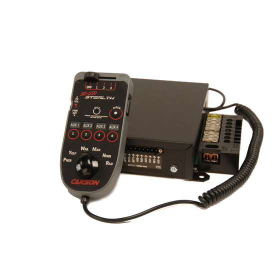
SC-550-10 Installation and Operating Instructions Page 3 GENERAL DESCRIPTION The SC-550 Remote Siren Amplifier with integrated Lighting Control is a premium unit designed for single or dual 100W speaker use. A remote hand control is connected to the amplifier with a thin cable. -
Page 4: Installation
Page 4 SC-550-10 Installation and Operating Instructions INSTALLATION Proper installation of the unit is essential for years of safe, reliable operation. Please read all instruction before installing the unit. Failure to follow these instructions can cause serious dam- age to the unit or vehicle and may void warranties. -
Page 5: Electrical Connections
SC-550-10 Installation and Operating Instructions Page 5 ELECTRICAL CONNECTIONS (2) #22 AWG Auxiliary Siren Input #22 AWG (See next page) Connect to output jack, terminals or Cutout Input #22 AWG (See next page) speaker of radio (2) #18 AWG RADIO (#16 - 2 SPKR) Slide Switch Non-Progressive Output 2 #22 AWG (500mA Max.) - Page 6 Page 6 SC-550-10 Installation and Operating Instructions ELECTRICAL CONNECTIONS Connections are made using pressure terminal connectors. Legends on the unit identify each terminal function. Attach leads by stripping 3/8", inserting into connector and clamp by tightening screw. Make sure the screw is tight and the wire can't be pulled out. Failure to adequately tighten the screw can result in improper operation or burning the connector and wire.
-
Page 7: Mounting
SC-550-10 Installation and Operating Instructions Page 7 L1, L2, L3 Outputs: These outputs are controlled by the slide switch in a progressive fashion. Outputs are fused. S1 to S4 Outputs: These outputs are controlled individually by pushbutton switch 1 to 4. -
Page 8: Operation
Page 8 SC-550-10 Installation and Operating Instructions OPERATION GENERAL This unit is designed for easy operation under the stress associated with high-speed pursuit. Most functions are accessible with one simple motion without repetitive activation of switches or automatic timed switching that can interfere with desired operation. -
Page 9: Light Controls
SC-550-10 Installation and Operating Instructions Page 9 LIGHT CONTROLS A 4-position slide switch provides control of primary lighting functions. It also provides automatic activation of the siren. Four pushbuttons for additional lighting or controlling other devices. The power switch on the hand control must be ON for light controls to function. -
Page 10: Service
Page 10 SC-550-10 Installation and Operating Instructions SERVICE This unit is designed to provide years of reliable service under even the worst conditions. Many times there may appear to be a problem with the unit when the true problem is in the speaker(s), controlled devices, or improper installation. -
Page 11: Parts
Returned Merchandise Authorization number (RMA#) before you ship the product to Carson. Please write the RMA# clearly on the package near the mailing label. Be sure to provide a return address, contact and phone number, along with a brief description of the problem. -
Page 12: Installation Information
Page 12 SC-550-10 Installation and Operating Instructions INSTALLATION INFORMATION MODEL: SC-550 _______________________ OPTIONS SERIAL NO: ___________________________ ______ Two-Tone instead of Phaser PURCHASE DATE: _____________________ ______ Phaser and Two-Tone Disable DEALER: ______________________________ ______ HRC enabled ______________________________________ ______ Horn disabled INSTALLER: ___________________________...
Need help?
Do you have a question about the SC-550-10 and is the answer not in the manual?
Questions and answers