Table of Contents
Advertisement
Quick Links
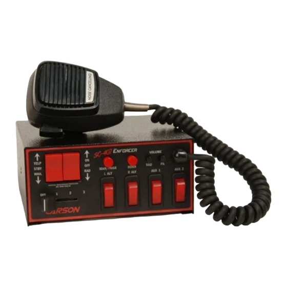
LIGHT CONTROL / SIREN AMPLIFIER
Ver. B has different Auxiliary and Cutout Input Polarity Options
YELP
STBY
WAIL
OFF
1
Carson
INSTALLATION AND OPERATING
Carson is a trademark of Carson Manufacturing Company, Inc.
Sound Hazard - Sound level from siren speaker (>120dBA @ 10 feet) may cause hearing damage.
Do not operate siren without adequate hearing protection for you and anyone in immediate vicinity.
(Ref. OSHA 1910.95 for occupational noise exposure guidelines)
Carson Manufacturing Co., Inc.
5451 North Rural Street
Indianapolis, IN 46220
Phone: (888) 577-6877
www.carsonsirens.com
SC-407 Ver. B
ON
OFF
RAD
MAN/PHSR
L ALY
2
3
INSTRUCTIONS
Fax: (317) 254-2667
SC-407
VOLUME
HORN
RAD
R ALY
PA
AUX 1
AUX 2
Advertisement
Table of Contents

Related Manuals for Carson SC-407 Ver. B


Summary of Contents for Carson SC-407 Ver. B
- Page 1 INSTALLATION AND OPERATING INSTRUCTIONS Carson is a trademark of Carson Manufacturing Company, Inc. Sound Hazard - Sound level from siren speaker (>120dBA @ 10 feet) may cause hearing damage. Do not operate siren without adequate hearing protection for you and anyone in immediate vicinity.
-
Page 2: Table Of Contents
Carson Manufacturing Co., Inc. makes no warranty of any kind with regard to this manual, including, but not lim- ited to, the implied warranties of merchantability and fitness for a particular purpose. -
Page 3: General Description
SC-407-10 Ver. B Installation and Operating Instructions Page 3 of 12 GENERAL DESCRIPTION The SC-407 Light Control/Siren is a premium unit designed for single or dual 100W speaker use and lighting control. The primary siren operating modes are Yelp, Wail, Standby and Radio. A Noise Canceling PA Override and push-button Horn Override are available in all modes except Radio. -
Page 4: Installation
Page 4 of 12 SC-407-10 Ver. B Installation and Operating Instructions INSTALLATION Proper installation of the unit is essential for years of safe, reliable operation. Please read all instruction before installing the unit. Failure to follow these instructions can cause serious dam- age to the unit or vehicle and may void warranties. -
Page 5: Siren Connections
SC-407-10 Ver. B Installation and Operating Instructions Page 5 of 12 Horn Disable - The Horn function can be disabled by cutting the trace on the back of the board at the location designated "cut to disable horn". Automatic Siren Disable - To disable automatic siren operation when Cut to →... -
Page 6: Light Control Connections
Page 6 of 12 SC-407-10 Ver. B Installation and Operating Instructions LIGHT CONTROL CONNECTIONS In addition to these instructions a label located on the bottom of the unit shows the light control switch connections. Fuses / Breakers The lighting control circuits of this unit are not fused. Automotive fuses or circuit breakers must be connected between the power source and the unit properly rated for the circuit requirements. - Page 7 SC-407-10 Ver. B Installation and Operating Instructions Page 7 of 12 Light Control Rocker Switch Connections The following diagram shows proper connection of the rocker switch leads located at the rear. Note: Negative (NEG) connection must also be made on 10-Pin plug for rocker switches to light WARNING: The lighting control circuits of this unit are not fused.
-
Page 8: Operation
Page 8 of 12 SC-407-10 Ver. B Installation and Operating Instructions OPERATION Sound Hazard - Sound level from siren speaker (>120dBA @ 10 feet) may cause hearing damage. Do not operate siren without adequate hearing protection for you and anyone in immediate vicinity. (Ref. -
Page 9: Horn Ring Cycler 2 (Optional)
SC-407-10 Ver. B Installation and Operating Instructions Page 9 of 12 Horn Ring Cycler 2 (Optional) During installation, the auxiliary input may be connected to the horn ring or other switching device, and the HRC2 option programmed. With the Selector Switch set to the STBY position, tap the horn ring to bring the unit out of standby into Wail tone. -
Page 10: Service
Page 10 of 12 SC-407-10 Ver. B Installation and Operating Instructions SERVICE This unit is designed to provide years of reliable service under even the worst conditions. Many times there may appear to be a problem with the unit when the true problem is in the speaker(s) or improper installation. -
Page 11: Parts
SC-407-10 Ver. B Installation and Operating Instructions Page 11 of 12 PARTS The following parts are available from Carson Manufacturing Company, Inc.: Part Description CP3966 Bolt, mounting, 1/4-20 X 3/8” (2 required) CP3571 Bracket, mounting CP4688-10 Connector, 10-Pin Terminal Block Plug... -
Page 12: Return
Returned Merchandise Authorization number (RMA#) before you ship the product to Carson. Please write the RMA# clearly on the package near the mailing label. Be sure to provide a return address, contact and phone number, along with a brief description of the problem.
Need help?
Do you have a question about the SC-407 Ver. B and is the answer not in the manual?
Questions and answers