Table of Contents
Advertisement
Quick Links
REMOTE SIREN
SA SA- - 430
430
INSTALLATION AND OPERATING
INSTRUCTIONS
Website: www.carsonsirens.com
Carson
MANUFACTURING COMPANY, INC.
SA-430
AMPLIFIER
RADIO
RADIO
SIREN
SIREN
HORN
HORN
MAN
MAN
W W AIL
AIL
ON
ON
YELP
YELP
PHASER
PHASER
5451 N. Rural Street
Indianapolis, IN 46220
Phone: (888) 577-6877
Fax: (317) 254-2667
PA
PA
VOL
VOL
Carson
Carson
POWER
POWER
Advertisement
Table of Contents

Related Manuals for Carson SA-430


Summary of Contents for Carson SA-430
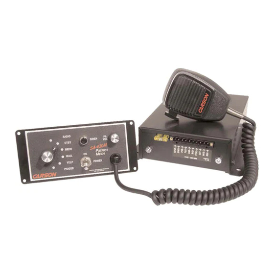
- Page 1 Carson MANUFACTURING COMPANY, INC. SA-430 REMOTE SIREN AMPLIFIER RADIO RADIO SIREN SIREN HORN HORN Carson Carson W W AIL YELP YELP POWER POWER PHASER PHASER SA SA- - 430 INSTALLATION AND OPERATING INSTRUCTIONS 5451 N. Rural Street Indianapolis, IN 46220...
-
Page 2: Table Of Contents
Page 2 SA-430 Installation and Operating Instructions TABLE OF CONTENTS SPECIFICATIONS ........................3 NOTICE............................ 3 GENERAL DESCRIPTION....................... 4 INSTALLATION........................5 SAFETY PRECAUTIONS ..................... 5 UNPACKING ........................5 MOUNTING – Control Head ....................6 ELECTRICAL CONNECTIONS – Control Head ..............6 MOUNTING –... -
Page 3: Specifications
Carson Manufacturing Co., Inc. makes no warranty of any kind with regard to this manual, including, but not limited to, the implied warranties of merchantability and fitness for a particular purpose. -
Page 4: General Description
SA-430 Installation and Operating Instructions GENERAL DESCRIPTION The SA-430 Siren Amplifier is a premium unit designed for single or dual 100W speaker use from a 12 volt DC power source (negative ground). The control head is only 1 inch deep and can be installed in minimum clearance areas. -
Page 5: Installation
SA-430 Installation and Operating Instructions Page 5 INSTALLATION Proper installation of the unit is essential for years of safe, reliable operation. Please read all instruction before installing the unit. Failure to follow these instructions can cause serious damage to the unit or vehicle and may void warranties. -
Page 6: Mounting - Control Head
Page 6 SA-430 Installation and Operating Instructions OPTION SWITCHES Various options can be controlled by turning on or off any of 8 DIP switches exposed in the amplifier. Switch 1 On: Two-Tone - Two-Tone replaces Phaser function. Switches 1 & 2 On: Phaser Disable - The Phaser function is disabled. - Page 7 SA-430 Installation and Operating Instructions Page 7 When connected to the red lead, make sure that the ignition switch controls the power to that connection. This prevents the panel lights from being continuously on. White: Control - Connect white leads from amplifier and control head. The connection may be extended with any size wire.
-
Page 8: Mounting - Amplifier
Page 8 SA-430 Installation and Operating Instructions MOUNTING – Amplifier Select a location for the amplifier in an area such as the driver compartment firewall, under a seat, etc. Mounting the amplifier in the engine compartment or in an area directly exposed to weather is not recommended. -
Page 9: Siren Testing
SA-430 Installation and Operating Instructions Page 9 Cutout Input Connection - The Cutout Input turns off any siren tone output when activated, and ADDED DOOR remains off until a control is activated or changed. SWITCH The adjacent diagram shows two connection... -
Page 10: Operation
Page 10 SA-430 Installation and Operating Instructions OPERATION GENERAL This unit is designed for easy operation under the stress associated with high-speed pursuit. Most siren functions are accessible with one simple motion without repetitive activation of switches or automatic timed switching that can interfere with desired operation. -
Page 11: Radio Volume
SA-430 Installation and Operating Instructions Page 11 RADIO VOLUME The radio repeat volume level is set using an adjustment on the side of the amplifier. Set the Selector Switch to the Radio position and turn on the power. With the radio volume set to normal level, adjust the siren radio repeat control to the desired level. -
Page 12: Service
Page 12 SA-430 Installation and Operating Instructions SERVICE This unit is designed to provide years of reliable service under even the worst conditions. Many times there may appear to be a problem with the unit when the true problem is in the speaker(s) or improper installation. -
Page 13: Parts
Department to obtain a Returned Merchandise Authorization number (RMA#) before you ship the product to Carson. Please write the RMA# clearly on the package near the mailing label. Be sure to provide a return address, contact and phone number, along with a brief description of the problem. -
Page 14: Limited Waranty
During this warranty period the obligation of Carson Manufacturing is limited to repairing or replacing, as Carson Manufacturing may elect, any part or parts of such product which after examination by Carson Manufacturing is determined to be defective in material and/or workmanship. -
Page 15: Control Head Installation Template
SA-430 Installation and Operating Instructions Page 15 CONTROL HEAD INSTALLATION TEMPLATE 03/22/02 CP4854B...
Need help?
Do you have a question about the SA-430 and is the answer not in the manual?
Questions and answers