Carson SC-1002 Installation And Operating Instructions Manual
Siren amplifier with light control
Hide thumbs
Also See for SC-1002:
- Installation and operating instructions manual (12 pages) ,
- Installation and operating instructions manual (16 pages)
Table of Contents
Advertisement
SC-1002 / 1012 / 1022-10
SIREN AMPLIFIER W/ LIGHT CONTROL
M
A
N
A
U
T
O
MAN
S
W
T
A
B
I
Y
L
AUTO
REMOTE PANEL
INSTALLATION AND OPERATING
Carson is a trademark of Carson Manufacturing Company, Inc.
Sound Hazard - Sound level from siren speaker (>120dBA @ 10 feet) may cause hearing damage.
Do not operate siren without adequate hearing protection for you and anyone in immediate vicinity.
(Ref. OSHA 1910.95 for occupational noise exposure guidelines)
Carson Manufacturing Co., Inc.
5451 North Rural Street
Indianapolis, IN 46220
Phone: (888) 577-6877
www.carsonsirens.com
MECH
WAIL
YELP
SC-1012
MECH
PHSR
LT1
YELP
HORN
OUTPUT
POWER
INSTRUCTIONS
Fax: (317) 254-2667
OUTPUT
PHSR
HORN
SC-1002
LT2
HAND
CONTROL
SC-1000
LT1
LT2
SC-1022
MAN
HORN
MECH
WAIL
YELP
PHSR
LT1
LT2
Advertisement
Table of Contents

Related Manuals for Carson SC-1002


Summary of Contents for Carson SC-1002
- Page 1 INSTALLATION AND OPERATING INSTRUCTIONS Carson is a trademark of Carson Manufacturing Company, Inc. Sound Hazard - Sound level from siren speaker (>120dBA @ 10 feet) may cause hearing damage. Do not operate siren without adequate hearing protection for you and anyone in immediate vicinity.
-
Page 2: Table Of Contents
Carson Manufacturing Co., Inc. makes no warranty of any kind with regard to this manual, including, but not limited to, the implied warranties of merchantability and fitness for a particular purpose. -
Page 3: General Description
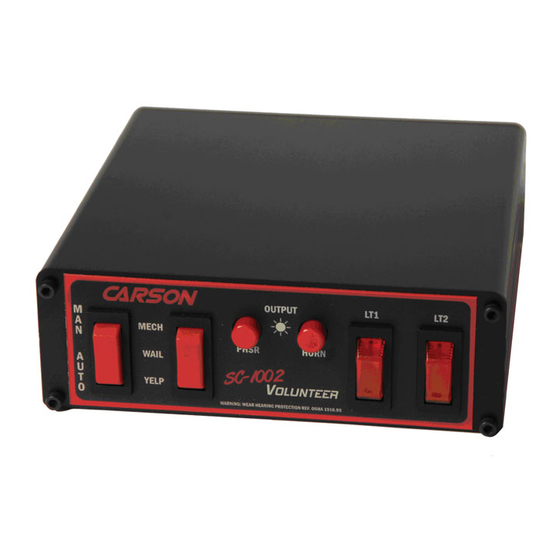
GENERAL DESCRIPTION The SC-1000 Series Siren Amplifier with Light Control is designed for single 100W speaker use. The SC-1002 and SC-1012 are a console unit and remote unit respectively. The SC-1022 is a remote hand held unit with pushbutton controls. -
Page 4: Installation
Page 4 of 16 SC-1002 / 1012 / 1022-10 14 Installation Instructions INSTALLATION Proper installation of the unit is essential for years of safe, reliable operation. Please read all instruction before installing the unit. Failure to follow these instructions can cause serious dam- age to the unit or vehicle and may void warranties. -
Page 5: Option Switches
SC-1002 / 1012 / 1022-10 14 Installation Instructions Page 5 of 16 OPTION SWITCHES An internal 8-position DIP switch on the circuit board may be changed to select various options. Accessing Option Switches - the DIP switch is located just behind the front panel of the ampli- fier. -
Page 6: Mounting
Page 6 of 16 SC-1002 / 1012 / 1022-10 14 Installation Instructions MOUNTING (Main unit) The mounting bracket supplied can be installed above or below the unit. Mounting bolts slide into channels Lockwashers on each side of the case. Lockwashers should be used between the case and bracket as well as be- tween the bracket and nut. -
Page 7: Electrical Connections
The required current is low (15mA typ.). Note: The unit may also be configured to power up without this connection on SC-1002 / 1012. See Instant ON under OPTION SWITCHES section. - Page 8 Page 8 of 16 SC-1002 / 1012 / 1022-10 14 Installation Instructions ELECTRICAL CONNECTIONS CONTINUED (ALL MODELS) +VDC +VDC MOMENTARY For Aux Input Connection FOOT Added SWITCH HORN HORN SPDT HORN If just a splice is made to Switch RING...
- Page 9 SC-1002 / 1012 / 1022-10 14 Installation Instructions Page 9 of 16 ELECTRICAL CONNECTIONS CONTINUED (SC-1012 only) Front of Unit REMOTE PANEL Plug into unit first for terminal identification 10-P Terminal Block Plug (CP4688-10) Plug installed this orientation Remote Panel wired to terminal block plug...
- Page 10 Page 10 of 16 SC-1002 / 1012 / 1022-10 14 Installation Instructions ELECTRICAL CONNECTIONS CONTINUED (SC-1022 only) Front of Unit HAND CONTROL Plug hand control into unit SC-1022 HORN MECH WAIL YELP PHSR Note: Cable may be extended with ED1753 Hand Control Cable Extension Kit.
-
Page 11: Operation (Sc-1002 / 1012 Model)
The unit is enabled (turned on) by applying positive voltage to the orange enable lead. On the SC-1002, backlight turns on. On the SC-1012 remote amplifier, POWER light comes on. This is normally controlled with the ignition switch on the vehicle. See INSTALLATION section. -
Page 12: Light Controls
Page 12 of 16 SC-1002 / 1012 / 1022-10 14 Installation Instructions OPERATION (SC-1002 and SC-1012 Models continued) LIGHT CONTROLS LT1 and LT2 LIGHTED ROCKER SWITCHES When turned on the rocker switch will light up and activate the corresponding light output. -
Page 13: Operation (Sc-1022 Model)
SC-1002 / 1012 / 1022-10 14 Installation Instructions Page 13 of 16 OPERATION (continued) SC-1022 Model Sound Hazard - Sound level from siren speaker (>120dBA @ 10 feet) may cause hearing damage. Do not operate siren without adequate hearing protection for you and anyone in immediate vicinity. -
Page 14: Service
Page 14 of 16 SC-1002 / 1012 / 1022-10 14 Installation Instructions SERVICE This unit is designed to provide years of reliable service under even the worst conditions. Many times there may appear to be a problem with the unit when the true problem is in the speaker, controlled devices, or improper installation. -
Page 15: Parts And Accessories
CP4990-250 Fuse, 25 Amp Mini Automotive (Lite) CP4748-2 Switch, Red Rocker ON - OFF - ON (Mech - Wail - Yelp) (SC-1002 / 1012) CP4751-2 Switch, Momentary Red Rocker Switch, (ON) - OFF - (ON) (Phsr - Horn) (SC-1012) CP4995-2... -
Page 16: Returns
Returned Merchandise Authorization number (RMA#) before you ship the product to Carson. Please write the RMA# clearly on the package near the mailing label. Be sure to provide a return address, contact and phone number, along with a brief description of the problem.
Need help?
Do you have a question about the SC-1002 and is the answer not in the manual?
Questions and answers