Advertisement
Quick Links
Advertisement

Subscribe to Our Youtube Channel
Related Manuals for SportsArt Fitness E880


Summary of Contents for SportsArt Fitness E880
- Page 1 E880 Elliptical Trainer Repair Manual SPORTS ART INDUSTRIAL CO., LTD.
- Page 2 1-1-1. Unit Illustration 1-1-2. Component Placement Illustration-Front 1-1-3. Component Placement Illustration-Back 1-1-4. E880 Electronic Component Placement Illustration – Display Board (Front) 1-1-5. E880 Electronic Component Placement Illustration – Display Board (Back) 1-1-6. E880 Electronic Component Placement Illustration -TFT LCD- Display Back 1-1-7.
- Page 3 5. Cable Connection Illustrations 5-1-1. E880 Display Board Cable Connection Block Diagram 5-1-2. E880 Display Component Illustration 5-1-3. E880 Display Board Indicator LED Placement and Explanation 5-1-4. E880 Display Board Cable Connector Placement 5-2-1. E880 TFT LCD Cable Connection Illustration 5-2-2.
- Page 4 E880 Repair Manual Table of Contents 【 】 6. Error Message 6-1. ERROR-8-1 6-2. ERR7 6-3. No Start Up 6-4. Soft Key Malfunction 6-5. Telemetry Heart Rate Malfunction 6-6.HTR Heart Rate Malfunction 6-7. Resistance is too Light or too Heavy 6-8.Stride Length Cannot be Adjusted...
- Page 5 E880 Repair Manual Table of Contents 【 】 7-8. Stride Motor Voltage Test at Drive Board 7-9. Electro-Magnet Voltage Test at Drive Board 7-10. Transformer Voltage Test at Drive Board 7-11. Optic Sensor Voltage Test at Drive Board 7-12. Key Board Key Switch Test 7-13.
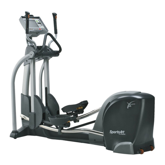
- Page 6 1.E880 Elliptical Trainer Unit Picture 1-1-1...
- Page 7 2. E880 Components – (1) Display Area Components Display Stride Remote Key Level Remote Key HTR Contact (right) HTR Contact (Left) Stride Support Assembly 1-1-2...
- Page 8 2. E880 Components-(2) Back Area Components Batteries Drive Board Electro- magnet Optic Sensor 1-1-3...
- Page 9 3.E880 Components – Display Board (Front) 1-1-4...
- Page 10 3.E880 Components – Display Board (Back) 1-1-5...
- Page 11 3.E880 Components – TFT LCD Display Board (Back) 1-1-6...
- Page 12 4.E880 Components – Drive Board 1-1-7...
- Page 13 5.E880 Components - Others Part Name Optic Sensor Part Name HTR Board Part Name HRC Board Fan Board Fan Board 1-1-8...
- Page 14 5. Components - Others Part Name LCD Screen Part Name Membrane Keys Part Name Key Board Part Name AV Terminal Board 1-01-09...
-
Page 15: Stride Length
1.E880 Specification Chart Specifica tion Details Notes Power 110 VAC / 220 VAC 10.2” TF T LCD Display 1.HRC W indow: 65%, 80%, Actual heartrate Main Wi ndow 2.Calorie s, Distance, Time, Strides/MIN, 3.Cal/HR , Stride Length, Watts, Total Strides 4. - Page 16 2. E880 Display Functions TFT screen shows various workout feedback Setting Window Shows setting values and workout goals 2-1-2...
- Page 17 3. Indicator Functions Workout Goal Indicators QuickStart Indicator Lit indicates active Lit indicates activation of Quick workout goal Start mode Workout Program Indicator Lit indicates entry into one of the following workout programs: Manual, Random, Plateau, Interval, Fat Burn,Vari-Stride, WT Loss, Cardio, Custom HR 2-1-3...
- Page 18 4. Key Functions Quick Start Key Press to enter Quick Start mode. Workout Goal Keys Press to set workout goal. Setting Value Window and Numerical Keys Fan Key Press to control fan speed. Workout Program Keys Press to enter Manual, Random, Plateau, Volume Adjust Interval, Fat Burn,...
- Page 19 E880 Display Operation 1. Start Up Function: Start and operate the unit. Operation: (1) Display shows “SPORTSART – E880”. After entering the start up screen 9 seconds, “SELECT PROGRAM OR QUICKSTART” appears. Press the QUICK START key to immediately start exercising or press the PROGRAM key to enter user settings.
- Page 20 2.Workout Level Keys Function: Set resistance level. Operation: (1) Press the LEVEL <▲> key. The Workout Level window shows increasing resistance LEVEL values. (2) Press the LEVEL <▼> key. The Workout Level window shows decreasing resistance LEVEL values. (3)Workout Level range: 1~20. 3.Stride Length Key Function Function: Set the stride length.
- Page 21 6.CLEAR Key Function Function: Clear feedback window values. Operation: After entering a value, you can clear it out to zero. 7.Program Function Function: Activate a workout program. Operation: (1) Press any workout PROGRAM key. The corresponding indicator LED lights. (2) Workout programs include MANUAL, RANDOM, PLATEAU, INTERVAL, FAT BURN, VARI-STRIDE, WT LOSS, CARDIO, CUSTOM HR.
- Page 22 11. CH+, CH – Key Function Function: Change TV channels. Operation: Press to change TV channels up or down. 12. Basic Settings Function: (1) Determine KM/MILE setting and see total distance, time, display, and drive board versions. Operation: (1) Press and hold the <ENTER> key for three seconds to enter basic setting mode. “UNIT - MILE”...
- Page 23 13. Lubrication Mode Setting Function: (1) Activate lubrication mode. Operation: (1) When “SELECT PROGRAM OR QUICKSTART” scrolls across the display,simultaneously press and hold <CALORIES>+<ENTER> for three seconds to enter lubrication mode. (2) After entering lubrication mode, the stride motors automatically adjust to the lubrication position. “OIL”...
- Page 24 1. E880 Display Cable Connection Block Diagram Key Board TFT LCD Board Soft Keys C-SAFE Board Display Board Telemetry Receiver Board Fan Board Board HTR Handlebars (Left, Right) Drive Board 4-1-1...
- Page 25 1. E880 TFT LCD Board Cable Connection Block Diagram TFT LCD Overlay CARDIO Board Inverter Board AV Board Display Board TFT LCD Drive Board TV Terminals Key Board 4-1-2...
- Page 26 2.E880 Drive Board Cable Connection Block Diagram Display Board Electro- Power On/Off Magnet Cord Switch FUSE Drive Board Optic Sensor Transformer Left Right Left Right Stride Stride Motor Motor 4-1-3...
- Page 27 1. E880 Display Board Cable Connection Block Diagram Key Board TFT LCD Board Soft Keys C-SAFE Board Display Board Telemetry Receiver Board Fan Board HTR Board HTR Handlebars (Left,Right) Drive Board 5-1-1...
- Page 28 2. E880 Components – Display Board (Back) 5-1-2...
- Page 29 3. E880 Display Board LED Indicators COMM Indicator Flashing indicates normal communication with the drive board. POWER Indicator Lit indicates reception of 5 VDC power supply from the drive board. 5-1-3...
- Page 30 4. E880 Display Cable Connections CON5 CON9 CON4 CON3 To CSAFE Board To 13-PIN soft keys To HTR board To HRC board CON8 To 8-PIN soft keys CON6 CON1 CON11 CON10 CON7 To drive board To handle keys To TFT board...
- Page 31 1. E880 TFT LCD Cable Connection Block Diagram TFT LCD Overlay CARDIO Board Inverter Board AV Board Display Board TFT LCD Drive Board TV Terminals Key Board 5-2-1...
- Page 32 2. E880 Components – TFT LCD Display Board (Back) TFT-LCD Board PCB INVERTER TFT LCD Display board HRC Board Key Board 5-2-2...
- Page 33 3. E880 TFT LCD Cable Connections FCON1,2: To TFT LCD CON8: To display board CON6 JP2 TV signal entry connector CON3: To INVERTER board To TFT LCD backlit source CON4: To display board CON6 CON1: To CARDIO board J3: To AV board...
- Page 34 1.E880 Drive Board Cable Connection Block Diagram Display Board Electro- Power On/Off Magnet Cord Switch FUSE Drive Board Optic Sensor Transformer Left Right Left Right Stride Stride Motor Motor 5-3-1...
- Page 35 2. E880 Components – Drive Board 5-3-2...
- Page 36 3. E880 Drive Board Indicator Placement and Explanation LED5 MOTOR LED (GREEN) Lit indicates drive board is sending voltage for stride motor upward movement. LED11 CLK LED (RED) Flashing indicates incoming optic sensor signal. LED4 Display VBB Power LED (GREEN)
- Page 37 3. E880 Drive Board Indicator Placement and Explanation-1 LED10 INCL_L_DN LED (GREEN) Lit indicates drive board is supplying power for STRIDE down operation. LED9 INCL_L_UP LED (RED) Lit indicates drive board is supplying power for STRIDE up LED1 VR2_ERR LED (RED) operation.
- Page 38 4. E880 Drive Board Cable Connector Placement and Definitions To electro-magnet and optic sensor To transformer To stride motors To display board To on/off switch 5-3-5...
- Page 39 E880 Error Message: ERROR-8-1 1. Definition: (1) Communication error between the display board CPU and the drive board program IC. 2. Block Diagram Display Board LED_COM LED2 SIGNAL_ERR Drive Board 6-1-1...
- Page 40 3. Operation Order Part Explanation Drive Board 1. The drive board processes information. 16 –PIN Cable 1. Signals travel the cable. 1. After start up, the display CPU reads communication signals. Display Board 2. When there is an error, “ERROR-8-1” appears. 4.
- Page 41 E880 Error Message: ERR 7 1. Definition: (1) Display CPU detects a stride signal value error. (2) The stride motor VR1, VR2 voltage exceeds the range of 0.5 to 4.5 VDC. 2. Block Diagram D isp la y B o a rd...
- Page 42 3. Operation Order Part Explanation 1. As the STRIDE motor operates up or down, VR1, VR2 voltage Stride Motor increases or decreases. 1. 22 VDC from the drive board travels via cable to the stride 10-PIN Cable motor. 2. The VR1,VR2 voltage travels to the drive board. 1.
- Page 43 4. Troubleshooting Order Part Troubleshooting 1. When VR1_ERR on the drive board lights, inspect the left VR. When VR2_ERR on the drive board lights, inspect the right VR. Stride VR 2. Test VR1 or VR2 voltage. Normal range: 0.6-4.45 VDC. 3.
- Page 44 E880 Error Message: Unit Will Not Turn On 1. Circumstance of Malfunction: Turn on unit power. Display does not beep. The display does not light. 2. Block Diagram Display Board Transformer 10-PIN Drive Board 6-6-1...
- Page 45 3. Operation Orde Part Explanatio an or er 1. The transformer provides power to the drive board. 10-P IN able 1. Transformer voltage travels to the drive board. Driv Bo rd 1. The dr ve board supplies voltage for all display functions. 1.
- Page 46 E880 Error Message: Soft Key Malfunction 1. Circumstance of Malfunction: (1) After turning on unit, the display operates as if keys were pressed, even though none have been pressed. (2) Press keys. There is no reaction. 2. Block Diagram 8-PIN...
- Page 47 3. Operation Order Part Explanation 1. W yo r press a soft key, the key circuit has continuity, So Keys creating signal. 1. TIME, DIST, CAL, POWER ON signals travel to the display 8-PIN Cab board. 1. Numbe r, ENTER and PROGRAM signals travel to the 13-P IN able display.
- Page 48 E880 Error Message: Telemetry Heart Rate Malfunction 1. Circumstance of Malfunction: (1) there is no heart rate value on the display. (2) The heart rate value differs too much from actual heart rate. 2. Block Diagram Telemetry Heart Display Rate Receiver...
-
Page 49: Troubleshooting
3. Operation Order Part Explanation The tele m try heart rate transmitter detects the human heart rate and Tele try T ransmitter transmits a signal to the telemetry heart rate receiver board. Telemetry R eceiver 1. The tel etry receiver board receives the transmitter signal. Board 1. - Page 50 E880 Error Message: HTR Malfunction. 1. Circumstance of Malfunction: (1) Place both hands on the HTR heart rate contacts. The display does not show a heart rate value. (2) Do not place hands on the HTR contacts. The display shows a heart rate value.
- Page 51 3. Operation Order Operatio 1. H TR c ontact on the handlebar detects pulse. dleb 1. From one 2-pin cable on each side, the HTR signals travel to the 5-pin cable. 1. From t he 2-pin cable on each side, the HTR signal travels the 5-pin ca le to the display board.
- Page 52 4. Troubleshooting Order Troubles hooting Clean HTR handlebar contacts. HTR Han dlebars 2. Test H TR cables. 2 IN Ca 1. Ins t the cables and their connections. 5 IN Ca 1. Ins t the cables and their connections. 1. Ins t the HTR board 4-PIN connections.
- Page 53 E880 Error Message: No Resistance or Resistance is Too High 1. Circumstance of Malfunction: (1) Turn on unit. Exercise. Press LEVEL ▲/▼ keys. Resistance does not change or there is no resistance. (2) Turn on unit. Resistance is so high the unit cannot be operated.
- Page 54 3. Operation Orde Explanati 1. D uring use, the electro-magnet attracts the flywheel, Elect ro- agnet creating r esistance. 2-PIN Ca ble 1. Drive oard voltage travels this cable to the electro-magnet. 1. As the flywheel rotates, the optic sensor generates a CLK Optic Sen sor signal.
- Page 55 4. Troubleshooting Orde Troubles hooting 1. In spec t whether there is resistance voltage while exercising. 2. Inspec t whether the electro-magnet has an electrical short Elec agnet or ope 3. Replac e the electro-magnet as a test. ble 1. Inspect the cable and its connections. 1.
- Page 56 E880 Error Message: Stride Length Will Not Change 1. Circumstance of Malfunction: 1. Press the Stride▲/▼ key. The display Stride Length window values change, but the stride length does not change. 2. Block Diagram D isp la y B o a rd...
- Page 57 3. Operation Orde Part Explanation 1. S trid e motor movement adjusts stride length. Stride Motor 2. Stri de motor movement moves the VR, which changes the VR (Lef ight) output voltage. 1. 22 V DC voltage travels to the stride motors. Cable 2.
- Page 58 4. Troubleshooting Order Troubleshooting 1. In ct the cables and their connections. Stride M otor 2. Inspe ct whether when you press the stride key, the drive board ht) emits v ltage to the stride motor. 3. Repl ce the stride motor as a test. PI Cable 1.
- Page 59 E880 Error Message: No Step Count 1. Circumstance of Malfunction: Exercise on the product. The STRIDES/MIN window on the display does not show any step count. 2. Block Diagram Display Board Optic Sensor 3-PIN Drive Board LED11_CL 6-9-1...
- Page 60 3. Operation Orde Part Explanatio 1. Th e dr ive board supplies all VBB power supply to the display board. Drive Boa 2. The dri ve board receives the optic sensor signal. 1. When someone exercises on the unit, the CLK signal is Optic en transmitte d to the drive board.
- Page 61 4. Troubleshooting Orde Troublesh ooting 1. Ins pect drive board CN5, CN6 cable connections. 2. Inspect drive board U4 IC connections. Replace as a test. Drive Boa 3. Replac e the drive board as a test. 1. Inspect whether the CLK signal when someone exercises. sor 2.
-
Page 62: Tft Lcd Board
E880 Error Message: No TV or DVD Reception on the TFT LCD 1. Circumstance of Malfunction: Turn on unit. Display turns on, but there is no TV or DVD reception. 2. Block Diagram 2-PIN TFT LCD Board FCON FCON TV Connection... - Page 63 3. Operation Order Part Explanation 1. TFT LCD driver board receives display signals. TFT LCD 2. TFT LCD driver board receives TV and AV board image Board signals. 3. Provides power supply to INVERTER board. 30-PIN Cable 1. Digital signals travel to the TFT LCD overlay. TV Connector 1.
- Page 64 4. Troubleshooting Order Part Troubleshooting 1. Inspect cable connections. TFT LCD 2. Inspect U8 program IC connections. Replace as a test. Driver Board 3. Replace the TFT LCD driver board as a test. 30-PIN Cable 1. Inspect the cable and its connections. 1.
- Page 65 E880 Error Message: TFT LCD shows an image but there’s no sound. 1. Circumstance of Malfunction: (1) Turn on unit. There is a TV or DVD image but no sound. 2. Block Diagram TFT LCD Driver Board CARDIO Board 3-PIN...
- Page 66 3. Operation Order Part Explanation 1. TFT LCD driver board accepts the TV and AV board image TFT LCD signals. Driver Board 2. And it provides sound to the CARDIO board. 3-PIN Cable 1 The signal travels from the driver board to the CARDIO board. 1.
- Page 67 E880 Error Message: TFT LCD Key Malfunction 1. Circumstance of Malfunction: (1) Turn on unit. TFT LCD keys do not operate. 2. Block Diagram CON4 Display Board CON6 5-PIN CON8 CON10 TFT LCD Driver Board CON1 Key Board 6-11-1...
- Page 68 3. Operation Order Part Explanation TFT LCD 1. TFT Driver Board receives display data. Driver Board 2. Adjust various TFT control signals. 5-PIN Cable 1. Signals travel to the TFT LCD driver board. 1. Display board receives key board key signals. Display Board 2.
- Page 69 E880 Display Board VCC Power Test 1. Diagram COMM Indicator POWER Indicator 7-1-1...
- Page 70 2. Test Procedure (1) Turn on unit power. Display POWER indicator lights. COMM indicator flashes. (2) Set voltmeter to the 20 VDC setting. Place probes as shown. (3) Normal reading: 5 VDC±0.2 VDC. (4) Display board beeps once, and display LEDs light. 7-1-2...
- Page 71 E880 Display Board VBB Voltage Test 1. Diagram COMM POWER 7-2-1...
- Page 72 2. Test Procedure (1) Turn on unit power. Display board POWER indicator lights. The COMM indicator flashes. (2)Put voltmeter to the 20 VDC setting. Place probes as shown. (3) Normal reading: 12±0.3 VDC. Diagram Normal reading 3. Troubleshooting If the display POWER indicator lights and there is not 12±0.3 VDC, inspect the following: (1) Is the data cable connected properly at the drive and display boards? (2) Is the data cable broken? (3) Replace Q6 IRF9540 or D1 SB860 on the drive board as a test.
- Page 73 E880 Display Board V Fan Voltage Test 1. Diagram POWER 2. Test Procedure (1) Turn on unit power. Display POWER indicator lights (2) Press the QUICK START key to operate the unit. Press the FAN key to toggle through (3) Put voltmeter to the 20 VDC setting. Place probes as shown below. Normal reading:12Vdc...
- Page 74 2. Test Procedure (1) Turn on unit power. Display board POWER indicator lights. (2) Press the QUICK START key to operate the unit. Press the FAN key to toggle through (3)Put voltmeter to the 20 VDC setting. Place probes as shown. Normal reading: 12±0.3 VDC. 3.
- Page 75 E880 Drive Board DC30_O Voltage Test 1. Diagram LED8 MOTOR P3 +30V hoop P6 GND hoop LED2 SIGNAL_ERR LED8 PWR 7-4-1...
- Page 76 2. Test Procedure (1) Put voltmeter to the 200 VDC setting. Place probes separately on P3 +30v and P6 GND hoops. (2) Normal reading: 30~32 VDC. Red probe on P3 hoop Black probe on P6 hoop Normal reading 7-4-2...
- Page 77 E880 Drive Board DC22_O Voltage Test 1. Diagram P2 +22V hoop LED4 PWR P1 GND hoop 7-5-1...
- Page 78 2. Test Procedure (1) Put voltmeter to the 200 VDC setting. Place probes separately on P2 +22V and P1 GND hoops. (2) Normal reading: 22~23 VDC. Red probe on P2hoop Black probe on P1hoop Normal reading 7-5-2...
- Page 79 E880 Drive Board VBB Voltage Test 1. Diagram P5 12V hoop P4 GND hoop LED4 VBB(12V) 7-6-1...
- Page 80 2. Test Procedure (1) Put voltmeter to the 200 VDC setting. Place probes separately on P5 VBB and P1 GND hoops. (2) Normal reading: 12~13 VDC. Red probe on P5 hoop Black probe on P1hoop Normal reading 7-6-2...
- Page 81 E880 Drive Board VCC Voltage Test 1. Diagram P6 GND hoop P9 VCC hoop LED8 VCC 7-7-1...
- Page 82 2. Test Procedure (1) Put the voltmeter at the 20 VDC setting. Place proves separately on the P9 VCC and P6 GND test hoops on the drive board. (2) Normal reading: 5±0.1 VDC. Red probe on VCC test hoop Black probe on GND test hoop Normal reading 3.
- Page 83 E880 Drive Board Stride Motor Voltage Test 1. Diagram LED14 MOTOR P4 GND 端 P4 +22V 端 7-8-1...
- Page 84 2. Test Procedure (1) Put voltmeter to the 200 VDC setting. Place meter probes separately on the p4 +22v and P6 GND hoops on the drive board. (2) Normal reading: 22~24VDC. (3) If the drive board is not emitting any voltage, the stride motor will not operate. Red probe on P4 hoop;...
- Page 85 E880 Electro-Magnet Voltage Test at the Drive Board 1. Diagram LED5 MOTOR P4 GND Hoop Electro-Magnet Voltage LED8 VCC Hoop 7-9-1...
- Page 86 2. Test Procedure (1) Put voltmeter to the 20 VDC setting. Place probes on the drive board P8 and P6 GND hoops. (2) Exercise on the unit. Normal readings are shown in the chart below. (3) If the drive board does not provide voltage to the electro-magnet, there will be no resistance. Put the red probe on P8;...
- Page 87 E880 Drive Transformer Test 1. Diagram CON3 Transformer Connections CON2Power Connections Drive Board 7-10-1...
- Page 88 2.Test Procedure 1. Inspect transformer wire connections at the drive board CON3 connector. 2. Set multi-meter to the AC 200V setting. 3. Turn on unit power. Place multi-meter probes on the connector for the transformer’s two red wires (or two blue wires on a 220V unit) as shown. 4.
- Page 89 E880 Optic Sensor Voltage Test 1. Test Configuration Fig. 1. Distance between optic sensor & reflective tape Fig. 2. Probe positions Reflective Sticker Infrared Sensor 3-7 mm Black Yellow Optic sensor board 711-1...
- Page 90 2. Test Procedure (1) Optic sensor to reflective sticker distance test Make sure that the infrared optic sensor is within 3-7 mm from the reflective sticker, as shown in Fig. 1. (2) Optic sensor signal test Put voltmeter to the 20 VDC setting. Place probes separately on optic sensor wire connectors. Exercise on the unit.
- Page 91 Keypad Test 7-12-1...
- Page 92 Test Procedure 1. Put the voltmeter to the 200 ohm setting. Place probes separately on key switch points A and B. 2. Do not press any keys. Voltmeter shows no reaction: OL (open line). 3. Press a key. Voltmeter shows 0 ohm. Circumstance of Malfunction 1.
- Page 93 HTR Cable (5-pin to HTR Left and Right Contacts) Test Fig. 1: Place black probe as indicated Fig. 2: Place red probe as indicated on HTR contacts A-->Right HTR Contact B-->Left HTR Contact (Note: There are three wires on the HTR board 5-pin cable.) 7-13-1...
- Page 94 2. Test Procedure (1) Do not turn on unit power. Remove display cover to access the HTR board 5-pin cable. (2) Put voltmeter to the 200 ohm setting. Place probes as shown in Fig. 1 and 2. Test HTR cable and ground for electrical shorts and opens. (3) Test as shown below.
- Page 95 E880 Telemetry Heart Rate Receiver Board Test Actual Heart Rate Telemetry Strap 7-14-1...
- Page 96 2. Test Procedure (1) Put the telemetry heart rate strap in place. (2) Press the QUICK START key and start exercising. Exercise with the telemetry strap within two feet from the display. (3) Within five seconds, the display shows the heart rate value. If no heart rate value appears, refer to troubleshooting.
- Page 97 E880 HTR Board Test 1. HTR Board Indicator LED Placement and Definitions LED3 LED4 LED2 LED1 2. Indicator Definitions Color Name Explanation LED1 Telemetry Indicator Flashing indicates incoming telemetry heart rate signal. LED2 Orange HTR Contact Lit indicates hands are holding HTR contacts.
- Page 98 2. Test Procedure The following indicates normal heart rate operation. 1. Do not hold onto the HTR handlebar. HTR board indicators do not light. 2. Hold onto the HTR handlebar with both hands. The HTR board LED2 indicator lights. 3. LED3 indicator flashes, indicating an incoming HTR handlebar signal. 4.
- Page 99 E880 Electro-Magnet Electrical Short Test 1. Diagram Fig. 1: Test Configuration Fig. 2: Electrical Short Test Wire-to-Cover Electrical Short Test 7-16-1...
- Page 100 2. Test Procedure (1) Electrical open test: Put voltmeter to the 200 Ω setting. Place probes as shown in Fig. 1. Normal test results are shown below. Note: a reading of just under 20Ω indicates the electro-magnet is OK. (2) Electrical short test: Put voltmeter to the 20 MΩ setting. Place probes as shown in Fig. 2. Normal test results are shown below.
- Page 101 2. Test Procedure (1) Open Test: Set voltmeter to the 200Ω setting. Test like colored wires. See test configuration 1. (2) Short Test: Set voltmeter to the 20MΩ setting. Test different colored wires. See test configuration 2. Normal Test Reading Open <20Ω...
- Page 102 E880 Rear Cover Removal Procedure Remove screw soft covers. 2. Remove left/right side small covers. 3. Remove 9 screws. 4. Remove rear cover. 8-1-1...
- Page 103 E880 Rear Cover Removal Procedure 1. Remove screw soft covers. 2. Lift to remove L/R side small covers. . Remove screws from both sides. 4. Remove screw from back. 8-1-2...
- Page 104 E880 Rear Cover Removal Procedure 5. While lifting the cover from the front about 6. This shows the completed procedure. 45 degrees, push toward the back. 8-1-3...
- Page 105 E870/E880 Drive Belt Tension Adjustment Adjustment Circumstances: After replacing a flywheel or after a long period of use, the drive belt may be too loose, requiring adjustment. Step 1. Use an 8 mm Allen wrench to screw the adjustment nut clockwise.
- Page 106 E870/E880 Drive Pulley Adjustment Procedure 1. Use an 8mm allen wrench to screw in the adjustment screw. 2. Measure spring top/bottom distance. Adjust to Turn clockwise to tighten. 56 mm length. 約 56mm Notes: 1. After replacing a flywheel, first adjust spring top/bottom distance to 56mm. Inspect whether the belt still slips.
Need help?
Do you have a question about the E880 and is the answer not in the manual?
Questions and answers