Table of Contents
Advertisement
Quick Links
E835 OWNER'S MANUAL CONTENTS
1. INTRODUCTION .............................................................................................................. 2
2. SAFETY PRECAUTIONS ................................................................................................. 3
3. WARNING LABLE POSITION .......................................................................................... 5
4. LIST OF PARTS ............................................................................................................... 6
5. ASSEMBLE THE PRODUCT ............................................................................................8
STEP 1 Install the Frame ..................................................................................................... 8
STEP 2 Install the Glide Rail ................................................................................................ 13
STEP 3 Install the Pedestal Covers ..................................................................................... 14
STEP 4 Install the Foot Pedals ........................................................................................... 15
STEP 5 Level the Product .................................................................................................... 17
STEP 6 Install the Ground Wire ........................................................................................... 18
STEP 7 Unit Inspection ........................................................................................................ 19
STEP 8 Beware of Moving Parts .......................................................................................... 20
6. UNDERSTAND THE E835 DISPLAY ................................................................................ 21
DISPLAY Overview ...............................................................................................................21
DISPLAY Specifications ...................................................................................................... 22
DISPLAY Windows ............................................................................................................... 22
DISPLAY Keys ..................................................................................................................... 22
7. OPERATE THE PRODUCT .............................................................................................. 24
OPERATION Safety Operating Area .................................................................................... 24
OPERATION Safety Get On/Off ........................................................................................... 25
OPERATION Proper Workout Position ................................................................................. 26
OPERATION Adjust Stride Length and Resistance Level .................................................... 27
OPERATION Quick Start ......................................................................................................28
OPERATION Start a Workout Program ................................................................................ 29
OPERATION Display ........................................................................................................... 31
OPERATION Cool Down ...................................................................................................... 32
OPERATION Workout Programs .......................................................................................... 33
OPERATION User Information and User Preference Setting.................................................... 36
8. ABOUT HEART RATE DETECTION ................................................................................ 38
HEART RATE Telemetry ...................................................................................................... 38
HEART RATE Contact ......................................................................................................... 38
9. GUIDELINES FOR EXERCISE ........................................................................................ 40
10. MAINTENANCE ............................................................................................................. 41
MAINTENANCE Safety Precautions .................................................................................... 41
MAINTENANCE Messages .................................................................................................. 41
MAINTENANCE Lubrication Procedure ............................................................................... 42
MAINTENANCE Schedule ................................................................................................... 43
MAINTENANCE Task List (Elliptical Trainers) ...................................................................... 44
MAINTENANCE One-Year Maintenance Log ....................................................................... 45
11. ACCESSORIES ............................................................................................................. 46
ACCESSORIES Standard............... .................................................................................... 46
ACCESSORIES Options ..................................................................................................... 47
12. APPENDIXES ................................................................................................................ 48
APPENDIXES Specifications ............................................................................................... 48
APPENDIXES Electronics Block Diagram ............................................................................ 49
*We reserve the right to revise this manual at any time without notice.
Advertisement
Table of Contents

Subscribe to Our Youtube Channel
Related Manuals for SportsArt Fitness E835


Summary of Contents for SportsArt Fitness E835
-
Page 1: Table Of Contents
STEP 6 Install the Ground Wire ................... 18 STEP 7 Unit Inspection ......................19 STEP 8 Beware of Moving Parts ..................20 6. UNDERSTAND THE E835 DISPLAY ................21 DISPLAY Overview .......................21 DISPLAY Specifications ...................... 22 DISPLAY Windows ....................... 22 DISPLAY Keys ........................ -
Page 2: Introduction
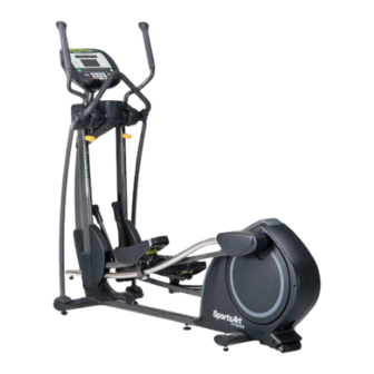
Congratulations on your purchase of one of the finest exercise products on the market today, the SportsArt E835 Elliptical trainer. Constructed of high quality materials and designed for years of reliable usage, this product was made to become an integral part of your commercial fitness venue. -
Page 3: Safety Precautions
2. SAFETY PRECAUTIONS Your SportsArt elliptical trainer was designed and built for optimum safety. However certain precautions apply whenever you use your elliptical trainer. Please read the entire manual before assembly and operation. Also, please note the following safety precautions: ●... - Page 4 2. SAFETY PRECAUTIONS (CONT.) Caution If you feel any pain or abnormal sensation, STOP YOUR WORKOUT and consult your physician immediately. Work within your recommended exer-cise level. DO NOT work to exhaustion. Before beginning any exercise program, you should consult with your doc-tor. It is recommended that you undergo a complete physical examination.
-
Page 5: Warning Lable Position
3. WARNING LABEL POSITION If you are a French speaking person in North America, please place the following label contained in the owner’s manual on the console as shown. Customers outside of North America will not receive this French warning label. (Note: If there are any other warning labels contained in the owner’s manual, please place them on the clearly displayed location on the console as well.) -
Page 6: List Of Parts
4. LIST OF PARTS Assembly Parts Name Qty. Name Qty. Main frame Support tube, left Stationary handlebar Support tube, right Pedestal covers, left A10 Foot pedals Stationary handlebar cover, left A11 Hardware kit Stationary handlebar cover, A12 Glide rail covers right Right roller cover A13 French Sticker (For USA) - Page 7 4. LIST OF PARTS (CONT.) Components in the Hardware Kit Name Qty. Specification Notes Mushroom top inner hex screw M10*P1.5*L20 Serrated washer D20*d10.2*t2.0 Secondary guide roller bolt D9.96*L54 Self-lubricating bushing Secondary guide roller D23*L45 Stride adjustment linkage cover Hex nut M10*P1.5 Stopper Ø30-30...
-
Page 8: Assemble The Product
5. ASSEMBLE THE PRODUCT Follow instructions below to assemble this product. Note that in this manual the words “left” and “right” are used to refer to the product and its parts. As such, these designations correspond to the “left” and “right” sides of a person in position to exercise on this product. Also, for brevity, the word “screws”... - Page 9 STEP 1 Install the Frame (CONT.) (e) A: Once slip the glide rail into (Part A) and then place the pedal carriage lightly on the glide rail support (Part B). Connect the guide roller on the bottom of the glide rail. (Please note the direction to insert the screw is from outside to inside) B: Unsecure the bolts (32) (33) from the left/right roller covers (A6) (A7) and then put the left/ right roller covers (A6) (A7) place and secure them (32) (33) as shown below.
- Page 10 STEP 1 Install the Frame (CONT.) (f) Put the stride linkage in place and use the bolt (34) and washer to secure it onto the stride support assembly and then press the stride adjustment linkage covers (12) into place as shown below.
- Page 11 STEP 1 Install the Frame (CONT.) (g) Secure stopper (13) on the front, bottom of both glide rails and then remove the unit from the lower box.
- Page 12 STEP 1 Install the Frame (CONT.) (h) (1) Loosely secure bolts (35) (36) A and B on both support tube (A8) (A9). At this point, do not tighten these bolts. (2) With hardware (37) shown in illustration I, secure the stationary handlebar (A2) at both sides and then tighten bolts (35) (36) at area A and B.
-
Page 13: Step 2 Install The Glide Rail
STEP 2 Install the Glide Rail Follow instructions (a) through (c) to install the glide rail. (a) Move part (A) of the glide rail to the upper left part of the flywheel within the 90-degree indication. Hook the part B onto the glide rail. (b) Turn part B clockwise as shown to a nearly horizontal position of the glide rail covers (A12). -
Page 14: Step 3 Install The Pedestal Covers
STEP 3 Install the Pedestal Covers Hold the pedestal covers in place. Use the screw driver provided to tighten screws (15) into the pedestal covers (A3). -
Page 15: Step 4 Install The Foot Pedals
STEP 4 Install the Foot Pedals Follow steps (a) through (b) to secure the support tubes. (a) There are rubber pads (A) on the foot pedals (A10). Fold the rubber pad (A) up to access screws. Secure the foot pedals (A10) onto the plate of main frame with screws (38) as shown. - Page 16 STEP 4 Install the Foot Pedals (Details) Follow instructions (a) through (c) to install the details of the foot pedals. (a) Make sure the middle nibs on the foot pedals (A10) are firmly placed into the middle holes on the foot pedals (A10). Pull the nibs through the foot pedals (A10) until they fit snugly in place. (b) Secure the front screws (shown as m1) on the foot pedals (A10).
-
Page 17: Step 5 Level The Product
STEP 5 Level the Product Please apply force to the end of the machine to check if the leveling knob is stable on the ground. If not, adjust the levelers as follows: (a) Loosen the leveling knob. (b) Rotate the leveling knob downward to the ground to make it steady. (c) Tighten the leveling knob. -
Page 18: Step 6 Install The Ground Wire
STEP 6 Install the Ground Wire Note: A ground wire and the following instructions are required by European safety standards. The ground wire is not required by North American safety standards. To avoid electric shock and current leakage, this product has an exterior ground wire. For your safety, connect this ground wire to the unit and to the building ground. -
Page 19: Step 7 Unit Inspection
STEP 7 Unit Inspection After completing the assembly, please follow instructions (a) through (b) below to inspect the unit. (a) Before plugging the power cord, make sure the unit is steady and on a level surface. If the unit is not steady, make adjustments according to the instructions “Level the product” of this manual. -
Page 20: Step 8 Beware Of Moving Parts
STEP 8 Beware of Moving Parts This product has moving parts that could be a danger to people and animals. During use, do not insert hands or other objects into the stride adjustment slot, the opening in the rear cover, or other areas in which such action might present a hazard. -
Page 21: Understand The E835 Display
6. UNDERSTAND E835 LED DISPLAY DISPLAY Overview The E835 elliptical trainer is designed for user convenience. With better feedback about your workout, you get better results. The following explains the display key and window functions. Please read this manual, understand the display functions, and thereby get optimum enjoyment and benefit from this product. -
Page 22: Display Specifications
6. UNDERSTAND E835 LED DISPLAY(CONT.) DISPLAY Specifications ● Workout level (resistance level): 1 - 40 ● Time: 0:00 - 300:00 ● Distance: 0.00 - 9999 km or mile ● Calories: 0.0 - 9999 kcal ● Heart Rate range: 35 -255bpm ●... - Page 23 6. UNDERSTAND E835 LED DISPLAY(CONT.) GLUTE – This workout program is designed to train the gluteal muscle group. There are 3 programs to select from. FIT TEST – Press this key to enter a FIT TEST program and start the fitness test.
-
Page 24: Operate The Product
7. OPERATE THE PRODUCT OPERATION Safe Operating Area (a) Safety clearance required as shown below. Do not allow people to be near this area when operating. (b) Noise emission under load is higher than without load. -
Page 25: Operation Safety Get On/Off
OPERATION Safely Get On/Off (a) Place your feet on floor and then hold the handles to steady self while stepping on the pedals as shown below. (b) Wait until pedals come to a complete stop and then hold onto handles for stability while carefully stepping off the elliptical. -
Page 26: Operation Proper Workout Position
OPERATION Proper Workout Position (a) Proper workout position for user is shown below. (b) Over exercising or improper workout form may result in serious injury. (c) User can hold onto handles for stability when getting on or getting off from the right/left side of the elliptical. -
Page 27: Operation Adjust Stride Length And Resistance Level
OPERATION Adjust Stride Length and Resistance Level Resistance level(1~40) and stride length (457mm~647mm) (18”~25.5”) can be adjusted as desired.When the stride length adjustment handle is in position, make sure that the front end of handle (indicated as A) goes through the bar. Resistance level can be made via keys on the display as shown. -
Page 28: Operation Quick Start
OPERATION Quick Start There are two ways to start operating this product, either through the QUICK START mode or through a workout program/goal. Time, distance and calories will count up. If a workout time limit is activated, time will count down, but distance and calories will count up continuously. In QUICK START mode, resistance begins at level 1;... -
Page 29: Operation Start A Workout Program
OPERATION Start a Workout Program To obtain more accurate calorie counts and target heart rates, operate the product via a workout program as follows: 1. Press a workout program key (MANUAL, INTERVAL, PLATEAU, RANDOM, GLUTE, FIT TEST, CUSTOM HR, CARDIO/WEIGHT LOSS) to select a workout program. - Page 30 OPERATION Start a Workout Program(CONT.) 4. The weight setting range is from 50 to 400 lb. (20 to 180 kg), with a default setting of 165 lb. (75 kg). Use +/- keys to adjust the setting. Press the ENTER or QUICK START key to confirm your setting and start exercising. Follow prompts to begin your workout.
-
Page 31: Operation Display
OPERATION Display 1. If the feedback window is at lower row, press RESISTANCE +/- key to adjust the resistance, the display will temporary switch to top row to show the adjustment. In 4 seconds, it will return to lower row. 2. -
Page 32: Operation Cool Down
OPERATION Cool Down Once the workout goal (time, distance, or calorie expenditure) has been obtained, the product will enter a two-minute cool down period. The display will count down from two to zero. When the countdown reaches zero, the cool down period will end. The message “REVIEW SUMMARY”... -
Page 33: Operation Workout Programs
OPERATION Workout Programs The following explains features of the workout programs. MANUAL This program allows you to manually control resistance. In manual mode, simply press RESISTANCE +/- keys to control resistance. INTERVAL There are three interval programs: INTERVAL1:1, INTERVAL1:2, INTERVAL 2:2. Each interval program includes two segments, a work segment and a rest segment. - Page 34 OPERATION Workout Programs(CONT.) FIT TEST The FIT TEST program is designed for physical fitness assessments. The program is set with a time limit; therefore it is not restricted by the program time limit setting at the engineering mode. After you press the FIT TEST key, the display will show “STARTING TEST” to begin this program.
- Page 35 OPERATION Workout Programs(CONT.) CARDIO/WEIGHT LOSS/CUSTOM HR In these heart rate control programs, the resistance level will automatically change to keep the exerciser’s pulse at the optimum rate for achieving his or her fitness goals. Target heart rates are calculated based on a standard “maximum” heart rate for the exerciser’s age.
-
Page 36: Operation User Information And User Preference Setting
OPERATION User Information and User Preference Setting User preference settings allow you to change default settings and review some historical data of this product. To access user preference settings, press the CHANGE DISPLAY key for 2 seconds during Banner page. Exit User Information/User Preference Settings and Change Display You may press and hold STOP key can be pressed to end the setting and return to Banner page. - Page 37 OPERATION User Information and User Preference Setting(CONT.) ● Language setting: the display will show the current country selected, such as “US”. Note: After 4 seconds, it will display “XX MILE H>H” or “XX KM H>H” (XX represents the country code). Press +/- keys to change the country. Press the ENTER key to confirm the selection.
-
Page 38: About Heart Rate Detection
8. ABOUT HEART RATE DETECTION Heart rate detection functions are selected at the time of purchase. Not every product has every type of heart rate detection. The following explains factors that influence the performance of two of the most common types of heart rate detection devices. - Page 39 8. ABOUT HEART RATE DETECTION(CONT.) Heart rate devices built into this product are not medical devices. Heart rate values are for reference only. Do not use them for medical diagnostic or treatment work. CAUTION: Heart rate detection and transmission devices have been known to interfere with the operation of pacemakers, possibly endangering human life.
-
Page 40: Guidelines For Exercise
9. GUIDELINES FOR EXERCISE HOW HARD SHOULD I EXERCISE? Studies show that to benefit from aerobic exercise, people need to maintain a certain heart rate during their workouts. Your heart rate training zone depends on your age and fitness level. The darkened area in the chart to the right represents the recommended heart rate training zone for people of various ages. -
Page 41: Maintenance
10. MAINTENANCE Maintenance topics are presented below in the following order: error messages, lubrication of the shoulder area, lubrication of the stride area, glide rail cleaning, maintenance schedule, task list, one-year maintenance log, and electronics block diagram. MAINTENANCE Safety Precautions ●... -
Page 42: Maintenance Lubrication Procedure
MAINTENANCE Lubrication Procedure Please follow instructions (a) through (d) to lubricate the product. (a) Remove the cap that covers the lubrication hole. (b) Use an automobile grease gun to apply red lithium bearing grease into the nozzle on the product. (c) After applying lubricant, detach and remove the grease gun. -
Page 43: Maintenance Schedule
MAINTENANCE Schedule If there is a need for maintenance of components, please visit the SportsArt website. cleaning requirements 1.directive 93/42/CEE 2.directive biocide 98/8/CEE The disinfectant has to be in compliance with Medical Device Directive 93/42/EEC (MDD) and Biocidal Products Directive 98/8/EC (BPD). It is suited for sensitive synthetic surfaces such as synthetic leather, polycarbonate (PC), acrylic glass and polysulfone, and for the keyboards and control panels. -
Page 44: Maintenance Task List (Elliptical Trainers)
MAINTENANCE Task List (Elliptical Trainers) Like cars, fitness products require maintenance. Regular maintenance extends product life, and failure to maintain products can void the manufacturer’s warranty. Copy the maintenance log sheet, and record maintenance work for each fitness product. Daily tasks 1. -
Page 45: Maintenance One-Year Maintenance Log
MAINTENANCE One-Year Maintenance Log Facility: ____________________________ Supervisor: ____________________________ Product model number: _______________ Serial number: _________________________ Start date: __________________________ End date: _____________________________ Week 1-7 Week 8-14 Week 15-21 Week 22-28 Daily Tasks Completed Week 29-35 Week 36-42 Week 43-49 Week 50-52 Daily Tasks Completed Weekly Tasks... -
Page 46: Accessories
11. ACCESSORIES There are accessories attached to this console; some are standard and some are optional. The following explains the details of each accessory and its function. ACCESSORIES Standard USB CHARGER The USB charger will provide 5V 500mA voltage for the smart phone or other devices charging. However it is not compatible with tablet PC, such as iPad. -
Page 47: Accessories Options
ACCESSORIES Options 1. External Mount TV Bracket... -
Page 48: Appendixes
12. APPENDIXES APPENDIXES Specifications Model E835 L : 2010 mm (79”) Dimensions W : 620 mm (24”) H : 1730 mm (68”) Overall Weight 123 kg (271 lbs) Maximum User 180 kg (400 lbs) Weight DC 12V Power Requirement 4.0 Ah... -
Page 49: Appendixes Electronics Block Diagram
APPENDIXES Electronics Block Diagram... - Page 50 Your Authorized Distributor...
Need help?
Do you have a question about the E835 and is the answer not in the manual?
Questions and answers
Hello how do i use the glute workout so it will remain on level 3 It keeps going back to glute 1 even after i select 3 and press enter thankk you
You cannot directly set the glute workout to remain on level 3. The GLUTE program includes three preset programs (GLUTE 1, GLUTE 2, GLUTE 3), and you can select one by pressing the GLUTE button until the desired program appears, then press ENTER to select it. The resistance level may change automatically during the workout based on the preset program design.
This answer is automatically generated