Table of Contents
Advertisement
Quick Links
E876 - 16 OWNER'S MANUAL CONTENTS
1. INTRODUCTION ............................................................................
2. SAFETY PRECAUTIONS ..............................................................
3. WARNING LABLE POSITION .......................................................
4. LIST OF PARTS ............................................................................
5. ASSEMBLE THE PRODUCT ..........................................................
STEP 1 Install the Main Frame ..........................................................
STEP 2 Install the Moving Parts ........................................................
STEP 3 Install the Support Tubes ....................................................... 12
STEP 4 Install the Stationary Handlebar .............................................. 13
STEP 5 Install the Console ..............................................................
STEP 6 Install the Pedals ..................................................................
STEP 7 Install the Pedestal Covers .................................................... 16
STEP 8 Move the Product into Place .................................................. 17
STEP 9 Level the Product ................................................................... 18
STEP 10 Power Cord Assembly ......................................................... 19
STEP 11 TV and Network Function .................................................... 20
STEP 12 Beware of Moving Parts .....................................................
STEP 13 Essential Functions Guide .................................................
STEP 14 Power Supply Protection(Circuit Breaker) ............................ 23
6. UNDERSTAND THE SENZA CONSOLE ......................................
DISPLAY Overview ...........................................................................
DISPLAY Console Panel ...................................................................
DISPLAY Specifications ..................................................................... 25
7. OPERATE THE PRODUCT ...........................................................
OPERATION Safe Operating Area ...................................................
OPERATION Safely Get On/Off ........................................................
OPERATION Proper Workout Position ............................................... 28
OPERATION Start Screen ................................................................
OPERATION Start your (GO) Workout ................................................ 30
OPERATION Workout Selection ........................................................ 31
OPERATION Workout Programs .......................................................
OPERATION During Exercise ...........................................................
OPERATION Workout Status ............................................................. 33
OPERATION Select Entertainment ..................................................... 34
OPERATION View Entertainment ....................................................... 35
OPERATION Workout Summary ........................................................ 36
OPERATION Idle Mode ..................................................................... 36
OPERATION Energy Smart Function ................................................. 36
OPERATION Precautions .................................................................
OPERATION SA WELL+ .................................................................... 37
3
4
6
7
9
9
10
14
15
21
22
24
24
24
26
26
27
29
32
32
36
Advertisement
Table of Contents

Subscribe to Our Youtube Channel
Related Manuals for SportsArt Fitness E876


Summary of Contents for SportsArt Fitness E876
-
Page 1: Table Of Contents
E876 - 16 OWNER’S MANUAL CONTENTS 1. INTRODUCTION ................2. SAFETY PRECAUTIONS .............. 3. WARNING LABLE POSITION ............4. LIST OF PARTS ................5. ASSEMBLE THE PRODUCT ............STEP 1 Install the Main Frame ............STEP 2 Install the Moving Parts ............ - Page 2 E876 - 16 OWNER’S MANUAL CONTENTS 8. ABOUT HEART RATE DETECTION ..........HEART RATE Telemetry ..............HEART RATE Contact ..............9. GUIDELINES FOR EXERCISE ............. 10. MAINTENANCE ................MAINTENANCE Safety Precautions ..........40 MAINTENANCE Error Messages ............41 MAINTENANCE Lubrication ............... 41 MAINTENANCE Lubrication Procedure ..........
-
Page 3: Introduction
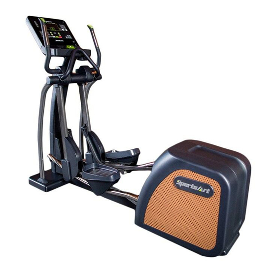
1. INTRODUCTION Congratulations on the purchase of a high quality SportsArt product, the E876 16” Senza Console Elliptical trainer. Constructed of high quality materials and designed for years of reliable performance, this product was made for full commercial use. Before this product is assembled or operated, we recommend that you familiarize yourself with this manual. -
Page 4: Safety Precautions
2. SAFETY PRECAUTIONS Your SportsArt elliptical trainer was designed and built for optimum safety. However certain precautions apply whenever you use your elliptical trainer. Please read the entire manual before assembly and operation. Also, please note the following safety precautions: ●... - Page 5 2. SAFETY PRECAUTIONS (CONTINUED) ● This elliptical trainer is not intended for use by persons (including children 12 or younger) with reduced physical, sensory or mental capabilities, or lack of experience and knowledge, unless they have been given supervision or instruction concerning use of this elliptical trainer by a person responsible for their safety.
-
Page 6: Warning Lable Position
3. WARNING LABLE POSITION If you are in a Non-English speaking country, you can attach the warning label to the console panel as shown, otherwise, you can also stick it on a place where is clear and obvious. (please use the French version label in French-Speaking areas in North America, and the label will not be included in the other regions.) Note: Depending on the model, the appearance of the console is different,... -
Page 7: List Of Parts
4. LIST OF PARTS Assembly Parts Name Qty. No. Name Qty. A1 Main frame Left joint cover A2 Right pedal A10 Right joint cover A11 Pedestal cover B A3 Left pedal A4 Left support tube A12 Pedestal cover E A5 Right support tube A13 Stationary handlebar A6 Console A14 Power cord... - Page 8 4. LIST OF PARTS (CONTINUED) TOOLS KIT Name Qty. Specification Notes Inner hex screw M10*P1.5*L25 Spring washer Washer D21*d10.5*t1.5 Stride adjustment linkage cover Hex nut M10*P1.5 Stopper Ø30-30 Secondary roller bolt D9.96*L67 Self-lubricating bushing Secondary roller D58*t23 L-shaped Allen wrench L-shaped Allen wrench T-shaped Allen Wrench M6*L108...
-
Page 9: Assemble The Product
5. ASSEMBLE THE PRODUCT STEP 1 Install the Main Frame (a) Unfold the main frame (A1) and make it stand. (b) Secure screws (10) to the main frame. -
Page 10: Step 2 Install The Moving Parts
STEP 2 Install the Moving Parts Follow instructions (a) through (f) to install the moving parts. (a) Remove screws (21) from the pedal arm attached to the main frame (A1). (b) Slip the glide rail into (area A), then gently place the pedal carriage on the glide rail support. - Page 11 STEP 2 Install the Moving Parts (Continued) (d) Separate the roller covers (A7). Snap them together into place on the product. Then secure them with screws (21). (e) On the left side of the product, remove the screw (22) from the stride adjustment linkage.
-
Page 12: Step 3 Install The Support Tubes
STEP 3 Install the Support Tubes Follow steps (a) through (b) to install the support tubes. (a) Remove support tube screws (23) (24) from the main frame (A1). (b) Insert left and right support tubes (A4,A5) into the axle area and base, and loosely secure them into place with screws (23) (24) -
Page 13: Step 4 Install The Stationary Handlebar
STEP 4 Install the Stationary Handlebar Follow instructions (a) through (c) to install the stationary handlebar and secure the support tubes. (a) Remove screws (25) from the stationary handlebar (A13). Insert the stationary handlebar (A13) into place on the support tubes, and secure them with screw (25). -
Page 14: Step 5 Install The Console
STEP 5 Install the Console Follow instructions (a) through (c) to install the console. (a) Remove screws (27), then pull the pedestal cover (28) upward and remove (b) Connect the cables of the console to the pedestal, and then secure the console into place with screw (29). -
Page 15: Step 6 Install The Pedals
STEP 6 Install the Pedals Follow instructions (a) through (d) to install the pedals. (a) Vertically split the right pedal (A2) with upper and lower halves, and then remove the non-slip pads on it. Repeat the same step with the left pedal. (b) Install the lower half of the right pedal (A2) at a tilt angle as shown below, and then press it into place. -
Page 16: Step 7 Install The Pedestal Covers
STEP 7 Install the Pedestal Covers Follow instructions (a) through (b) to install the pedestal covers. (a) Insert the pedestal cover (28) to the console at a tilt angle as shown in figure (a), and then place the pedestal cover onto the mount by a downward push. -
Page 17: Step 8 Move The Product Into Place
STEP 8 Move the Product into Place There are two techniques for moving this product. (a) One person: Grip the front base of the product and lift upward, then push the product into location for use. Be careful to avoid pinching fingers when setting the product down. -
Page 18: Step 9 Level The Product
STEP 9 Level the Product For the user’s safety and the proper functioning of the product, this elliptical trainer must sit level on a flat floor. If necessary, adjust the levelers by following instructions (a) through (c) below. (a) Loosen the leveler nut. (b) Rotate the leveler foot downward so it firmly touches the floor. -
Page 19: Step 10 Power Cord Assembly
STEP 10 Power Cord Assembly (1) Please remove the pre-installed screws (33) from the machine prior to assembly. (2) Push the plug cover of the power cord toward and against the plug. (3) Plug in the power cord (A14) and secure it with the screws (33). The picture below is for your reference. -
Page 20: Step 11 Tv And Network Function
STEP 11 TV and Network Function (a) NETWORK: Connect to the Ethernet with the external network signal. (b) AV PORT: To support external DVD PLAYER or other multimedia players using AV output signal. (c) To support MYE Wireless TV Audio_Channel Receiver, and the other equipment that conform to the CSAFE specification. -
Page 21: Step 12 Beware Of Moving Parts
STEP 12 Beware of Moving Parts This product has moving parts that could be a danger to people and animals. During use, do not put hands or other objects into the stride adjustment slot, the rear cover opening, or other areas in which such action might present a hazard. -
Page 22: Step 13 Essential Functions Guide
STEP 13 Essential Functions Guide LENGTH: Adjust the distance between two successive placements of the same foot. RESISTANCE: Adjust the weight or force you need to place on the pedals to push them. -
Page 23: Step 14 Power Supply Protection(Circuit Breaker)
STEP 14 Power Supply Protection(Circuit Breaker) When current is overloaded, the Circuit Breaker will work to protect the machine from damage. In the following picture (a) you will find a round button(D), which is the device of circuit breaker, it will pop up when current is overloaded, please turn off the machine in this situation. -
Page 24: Understand The Senza Console
6. UNDERSTAND THE SENZA CONSOLE DISPLAY Overview E876 Series 16” Senza Console is designed to help users obtain their fitness goals in a simple and convenient way. Before using the elliptical trainer, please familiarize yourself with the functions of this display console to obtain opti-mum benefits and enjoyment from this product. -
Page 25: Display Specifications
DISPLAY Specifications Parameter Spec. SPEED 0.1 mph (kph) RESISTANCE 1-40 STRIDE LENGTH 450 - 730mm or 17” - 29” CAL/HR 0-9999 K-CAL TIME 0:00-600:00 DISTANCE 0.00-9999 Mile/KM CALORIES 0-9999 K-CAL 5-150 HEART RATE 35-220 bpm TOTAL STRIDES 0 - 9999... -
Page 26: Operate The Product
7. OPERATE THE PRODUCT OPERATION Safe Operating Area (a) Safety clearance required as shown below. Do not allow people to be near this area when operating. (b) Noise emission under load is higher than without load. 600mm(23.6") -
Page 27: Operation Safely Get On/Off
OPERATION Safely Get On/Off (a) Place your feet on floor and then hold the handles to steady self while stepping on the pedals as shown below. (b) Wait until pedals come to a complete stop and then hold onto handles for stability while carefully stepping off the elliptical. -
Page 28: Operation Proper Workout Position
OPERATION Proper Workout Position (a) Proper workout position for user is shown below. (b) Over exercising or improper workout form may result in serious injury. (c) User can hold onto handles for stability when getting on or getting off from the right/left side of the elliptical. (d) This product is intended for exercise arms and legs. -
Page 29: Operation Start Screen
OPERATION Start Screen Touch screen design is simple and clear. The screen layout helps users focus on exercise. It provides many workout modes that can help you achieve your fitness goal. The following sections introduce information concerning touch screen operation, the available types of workout, and how to start the workouts. -
Page 30: Operation Start Your (Go) Workout
OPERATION Start your (GO) Workout By using the (GO) workout, exercise is started in the manual workout mode. The default user age is 35 and default weight is 75 kg (165 lbs). You can proceed by using these default settings or change the settings. How to start the (GO) workout: 1. -
Page 31: Operation Workout Selection
OPERATION Workout Selection Tap on the Select icon to access “SELECT WORKOUT”. 1. If you are pedaling, the workout will start right after a 3 second countdown timer. 2. If you are not pedaling, you can pick the option that you want. Select workouts on the screen: By swiping with your fingers, you can move between the workout options on the screen. -
Page 32: Operation Workout Programs
OPERATION Workout Programs Workout program details are explained below. QuicK START A workout mode option based on time, distance and calories that allows user to start a workout immediately. PLATEAU Various workout mode options are provided to achieve workout goal. INTERVAL (1:1, 1:2, 2:2) Interval Training is alternating periods of high intensity aerobic exercise and low intensity aerobic exercise. -
Page 33: Operation Workout Status
OPERATION Workout Status During the workout, you can select the “VIEW Dashboard” page below the screen to check the exercise status of your workout process. There are a total of 9 status windows for various information views, and you can modify the information display format in the status windows by touching the▼symbol below the status windows. -
Page 34: Operation Select Entertainment
OPERATION Workout Status (Continued) Drop down Menu items Symbol Default Other Options Total Distance Distance Remaining Calories/Min Calories Calories/Hour Mets Average SPM OPERATION Select Entertainment You can select the “Select Entertainment” page below the screen, and the available multimedia features will be displayed. The features include TV, Internet, SENZA Journeys, Bluetooth Audio, IPTV and AVIN, etc.: the small central window will display the selected multimedia screen immediately. -
Page 35: Operation View Entertainment
OPERATION View Entertainment The console displays the media window in maximum frame size. If you want to check your workout status, simply tap the taskbar at the bottom of the screen. That way, you can evaluate your training status and adjust the workload accordingly. -
Page 36: Operation Workout Summary
OPERATION Workout Summary At the end of a workout or when you press the stop button, the workout summary screen will appear. The screen shows your current workout status. OPERATION Idle Mode When the elliptical trainer stops running with no other activity for 2 minutes, the machine will enter the idle mode and the display will randomly show the standby picture. -
Page 37: Operation Sa Well
OPERATION SA WELL+ Tap SA WELL+ to enter SA WELL+ Login page. First time user must create an user account with SA WELL+ App. After sign up, user information will be saved into the account. Login to your SA Well+ account to track your workouts and will also allow you to download a created custom workout to machine. -
Page 38: About Heart Rate Detection
8. ABOUT HEART RATE DETECTION Heart rate detection functions are selected at the time of purchase. Not every product has every type of heart rate detection. The following explains factors that influence the performance of two of the most common types of heart rate detection devices. -
Page 39: Guidelines For Exercise
● Low systolic blood pressure makes it difficult to detect heart rate. ● Dry, course palms impede heart rate detection. For best results, moisten your palms. But do not apply hand lotion immediately prior to your workout, be- cause hand lotion can gum up the contact pads. Heart rate devices built into this product are not medical devices. -
Page 40: Maintenance
At the end of your workout, gradually decrease your workload. Then exercise lightly to cool down. HOW OFTEN SHOULD I EXERCISE? Research indicates that to achieve the greatest benefit, people should exercise three to five times per week. It is important to allow sufficient time, at least 24 hours, for your body to recover after exercise. -
Page 41: Maintenance Error Messages
the unit to fail and void the warranty. We will not be responsible for any safety issue that arises due to the misuse of accessories or parts. At the same time, we will terminate the warranty terms of this equipment. ●... -
Page 42: Maintenance Lubrication Procedure
MAINTENANCE Lubrication Procedure (a) Push in at point A, and slide upward to remove the lubrication cover. (b) Press the stride up key to adjust the stride to its longest point. Note the grease fitting at area B. (c) Use an automobile grease gun with red lithium grease. Apply the grease to the nozzle on the product. -
Page 43: Maintenance Cleaning The Glide Rails
MAINTENANCE Cleaning the Glide Rails Follow the steps below to clean left and right glide rails on a daily basis: (a) Use a clean, lint-free cloth to wipe dust and debris off the glide rails. (b) Test operate the product to determine where dirt might remain on the glide rails. -
Page 44: Maintenance Schedule
MAINTENANCE Schedule Area Week Month Quarter Year Notes Exterior Clean. ● Inspect and secure loose Screws ● parts Wipe away dirt and Glide rail ● debris. -
Page 45: Accessories
Rollers Apply silicone lubricant.. ● Stride motor Apply bearing grease ● Lubricate with original Cushion ● 66A lubricant. 11. ACCESSORIES ACCESSORIES Standard USB CHARGER The USB charger will provide 5V and 1.5A voltage for charging of smart phone or other devices. However it is compatible only with some tablets, such as iPad. -
Page 46: Accessories Option
Compatible with CSAFE (Communications Specification for Fitness Equip ment) Protocol. To support MYE Wireless TV Audio_Channel Receiver, and the other equipment that conform to the CSAFE specification. ACCESSORIES Option SA WELL+ Member System This is designed specially by SportsArt to assist the user in managing their workout history. -
Page 47: Accessories Mye Wireless Tv Audio_Channel Receivers
2. Use USB Flash Drive to store the workout data. 3. Manage user information and workout data Visit “www.gosportsart.com” for more information about this feature. Name of Function button USB port This port is used for optional data transferring. When a smart phone is connected wirelessly to Bluetooth/WIFI the unit, press this button to disconnect. -
Page 48: Appendixes
● ● ● ● ● ● ● ● ● ● ● ● ● ● ● ● ● ● ● ● ● ● ● ● ● ● ● ● ● ● ● ● MYE Wireless TV Audio channel Transmitters Earphone MYE Wireless TV Audio channel Receivers 12. APPENDIXES APPENDIX Specifications Model E876 16’’... -
Page 49: Appendixes Electronics Block Diagram
L : 2222 mm (87.5”) Dimensions W : 670 mm (26.4”) H : 1750 mm (69”) Overall Weight 186 kg (410 lbs) Maximum User 150 kg (330 lbs) Weight 100 – 120 V / 60 Hz (USA) Power Requirement 220 – 240 V / 50 Hz (EUROPE) Circuit Breaker 110 V : 2A Current Rating... -
Page 50: Appendixes Exploded Diagrams
SA WELL Option SA WELL+ Connection SA WELL Board HTR Board Display Board Control Board USB Board RFID Board WIFI Board TV Board USB Board EUP Board Bluetooth Board NFC Board Headphone Board HRC Board Rocker Board STRIDE LEVEL Contact HTR plates Stepper Motor Model no. - Page 51 APPENDIX Exploded Diagrams (Continued)
- Page 52 APPENDIX Exploded Diagrams (Continued)
-
Page 53: Appendixes Disassembly
APPENDIX Disassembly (a) Main Frame... - Page 54 (b)Lift Motor Assembly (c)Front Base Cover...
Need help?
Do you have a question about the E876 and is the answer not in the manual?
Questions and answers