Table of Contents
Advertisement
Quick Links
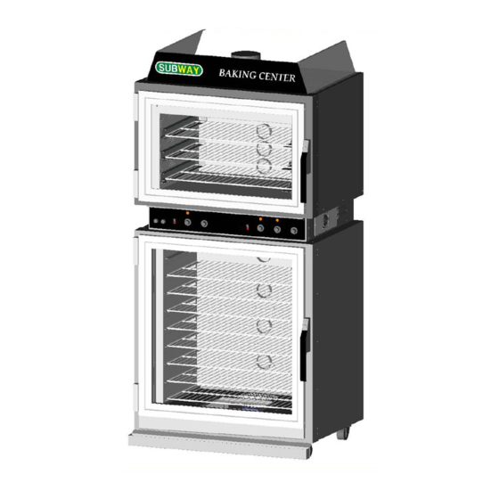
AHPO / EPO
PROOFER OVEN
MODELS
AHPO-6/18
EPO-3/9
Please read this manual completely before attempting to install,
This document is prepared for trained Duke service technicians. It is not to be used by anyone not properly qualified
to perform these procedures.
This Service Manual is not all encompassing. If you have not been trained on servicing this product, be sure to
read the manual completely before attempting servicing. Be sure all necessary tools, test equipment, and skills are
available. Those procedures for which you do not have the proper skills and test equipment must be performed only
by a qualified Duke trained service technician.
This manual is Copyright © 2009 Duke Manufacturing Co. All rights reserved.
Reproduction without written permission is prohibited. Duke is a registered
operate or service this equipment
trademark of the Duke Manufacturing Co.
Duke Manufacturing Co.
2305 N. Broadway
St. Louis, MO 63102
Phone: 314-231-1130
Toll Free: 1-800-735-3853
Fax: 314-231-5074
www.dukemfg.com
Service Manual
BA KI NG CE NT ER
P/N 512981B
Advertisement
Table of Contents

Related Manuals for Duke AHPO-6


Summary of Contents for Duke AHPO-6
- Page 1 Those procedures for which you do not have the proper skills and test equipment must be performed only by a qualified Duke trained service technician. This manual is Copyright © 2009 Duke Manufacturing Co. All rights reserved. Reproduction without written permission is prohibited. Duke is a registered trademark of the Duke Manufacturing Co.
-
Page 2: Important Warning And Safety Information
Service Manual for AHPO / EPO Proofer Oven IMPORTANT WARNING AND SAFETY INFORMATION IMPORTANT FOR YOUR SAFETY READ THIS MANUAL THOROUGHLY BEFORE OPERATING, INSTALLING OR PERFORMING MAINTENANCE ON THE EQUIPMENT. Failure to follow instructions in this manual can cause property damage, injury or death. -
Page 3: Table Of Contents
Service Manual for AHPO / EPO Proofer Oven TABLE OF CONTENTS INTRODUCTION ............................4 INSTALLATION ............................. 4 OPERATION ............................4 CLEANING ............................4 TOOLS ................................ 4 STANDARD ............................4 SPECIFICATIONS ............................5 REMOVAL AND REPLACEMENT OF COMPONENTS ................6 ELECTRICAL LOCKOUT/TAGOUT PROCEDURE ................6 COVERS AND PANELS ........................ -
Page 4: Introduction
Service Manual for AHPO / EPO Proofer Oven TOOLS INTRODUCTION STANDARD INSTALLATION • Standard set of hand tools. For detailed installation instructions, refer to the Owner’s Manual (502821A). • VOM with AC current tester. (Any quality VOM or DVM with a sensitivity of at least 20,000 Ohms per Volt can be used.) OPERATION •... -
Page 5: Specifications
Service Manual for AHPO / EPO Proofer Oven SPECIFICATIONS U.S. Patent. Other US and Foreign Patents Pending Model AHPO or EPO Shipping Weight: Carton Box 625 lbs / 284 kg Shipping Weight: Wooden Crate 760 lbs / 345 kg Volts Phase Watts Amps... -
Page 6: Removal And Replacement Of Components
Service Manual for AHPO / EPO Proofer Oven REMOVAL AND REPLACEMENT OF COMPONENTS ELECTRICAL LOCKOUT/TAGOUT Most service can be accomplished without moving the PROCEDURE unit from its mounted position. However, if the unit is moved during service, then these securing devices must be reinstalled for continued protection against tip-over Before performing any service that and to meet other compliance regulations. -
Page 7: Oven Fan Cage And Wire Harness Cover
Service Manual for AHPO / EPO Proofer Oven 2. Remove the Center Panel to gain access to Light Fixtures Proofer Floor Panel and wiring harness. Disconnect the electrical power to The Center Panel side screws must be removed the unit and follow lockout / tagout procedures. when removing either of the side panels. -
Page 8: Oven Ceiling Panel
Service Manual for AHPO / EPO Proofer Oven Figure 5. Oven Components with Ceiling Panel Removed Control Panel Figure 6. Components on Left Side of Control Panel Disconnect the electrical power to the unit and follow lockout / tagout procedures. It is not necessary to move the unit to gain access to the Control Panel. -
Page 9: Ac Power Access Panel
Service Manual for AHPO / EPO Proofer Oven Figure 8. AC Access and Connect Block with Panel Removed Figure 10. Possible Wiring Block Configurations The AC Power Access Panel is located on the right side of the unit next to the Control Cooling Fan. If the service procedure requires the removal of any covers or the Control Panel, then verify that there is no voltage present Remove the two screws securing the panel to the unit to gain... -
Page 10: Control Panel Cooling Fan
Service Manual for AHPO / EPO Proofer Oven Disconnect the electrical power to the unit and follow lockout / tagout procedures. Earlier This fan is mounted to a ventilated metal panel to the right models of the Operator’s Control Panel and on the right hand side of the unit. -
Page 11: Buzzer
Service Manual for AHPO / EPO Proofer Oven Also, observe fan for proper rotation. Breaker and push it out through the front of the Access Panel. 5. Reverse this procedure to install a new Proofer Lights BUZZER Circuit Breaker. Use these procedures when installing a new Proofer Lights Disconnect the electrical power to Circuit Breaker Kit to a unit with halogen lights: the unit and follow lockout / tagout procedures. -
Page 12: Oven Power Switch
Service Manual for AHPO / EPO Proofer Oven front of the control panel. Oven 3. Tag and disconnect the Oven Power Switch wires. Thermostat Oven Power Switch Figure 16. Location of Oven Thermostat 6. Remove the Thermostat Bulb from its wire form support in the top of the oven. -
Page 13: Proofer Power Switch
Service Manual for AHPO / EPO Proofer Oven Oven Proofer Timer Power Switch Figure 19. Location of Proofer Power Switch Figure 18. Location of Oven Timer 4. Reverse the procedure to install a new Proofer Power Switch. 5. Reverse this procedure to install new Oven Timer. PROOFER THERMOSTAT PROOFER POWER SWITCH Disconnect the electrical power to... -
Page 14: Proofer Humidity Control
Service Manual for AHPO / EPO Proofer Oven Proofer Thermostat Proofer Bulb Humidity Control Figure 22. Location of Proofer Humidity Control Figure 21. Proofer Thermostat Bulb Reverse this procedure to install a new Proofer Humidity Control. It may be necessary to remove the right side Rack Panel from the inside of the Proofer to pull the PROOFER TIMER Thermostat Bulb out. -
Page 15: Proofer Heat Elements
Service Manual for AHPO / EPO Proofer Oven Disconnect the electrical power to the unit and follow lockout / tagout procedures. There are two Heat Elements, one on the left rear and one on the right rear of the Proofer section. It is not necessary to replace both elements if only one has failed. -
Page 16: Proofer Circulation Fan
Service Manual for AHPO / EPO Proofer Oven PROOFER CIRCULATION FAN Right Side Heat Element Disconnect the electrical power to Humidity the unit and follow lockout / tagout procedures. Element The Proofer Circulation Fan is located in the floor of the Proofer. -
Page 17: Oven Heat Elements
Service Manual for AHPO / EPO Proofer Oven the unit and follow lockout / tagout procedures. 5. Tag and disconnect the Element wires. 6. Using an Ohmmeter, check the Element for continuity. There are two Oven Heat Elements, one on each side of oven. The Elements are behind the Oven Ceiling Panel. -
Page 18: Oven Hi-Limit Thermostat
Service Manual for AHPO / EPO Proofer Oven 7. Remove the four bolts securing the Oven Circulation Gasket Fan to the top of the Oven. Groove 8. Lift the Fan Motor out of the unit from the top. 9. Reverse these procedures to install a new Oven Circulation Fan. -
Page 19: Adjustments
1. With the door closed, remove the hinge covers and loosen Refer to Duke Manufacturing Co. publication 512994 for (don’t remove) the six screws that hold the hinges to further information. -
Page 20: Air Wash Door Adjustment
Service Manual for AHPO / EPO Proofer Oven Gasket is slightly Gasket compressed is slightly compressed Figure 37. Proper Hinge Side Adjustment Figure 38. Proper Door Handle Side Adjustment 4. Adjust the door position by moving the door frame to seal any gap between the gasket and the oven front near 5. -
Page 21: Stainless Steel Care
Service Manual for AHPO / EPO Proofer Oven CAUTION: Never use any metal tools. Scrapers, files, wire brushes or scouring pads (except for stainless steel scouring pads) will mar the surface. GENERAL CLEANING CAUTION: Never use steel wool, which will leave behind particles that rust. -
Page 22: Troubleshooting
Service Manual for AHPO / EPO Proofer Oven TROUBLESHOOTING SYMPTOM CAUSE REMEDY Oven and Proofer not working No power to unit Check plug for proper connection. If OK, check circuit breaker. Oven/Proofer Lights not working Oven Power Switch not turned on Turn Oven Power Switch on Proofer Power Switch not turned on Turn Proofer Power Switch on... -
Page 23: Electrical Schematic
Service Manual for AHPO / EPO Proofer Oven ELECTRICAL SCHEMATIC WIRING DIAGRAM AHPO-6/18 & EPO 3/9 (50/60 Hz) COOLING FAN PROOFER CIRCUIT BREAKER SWITCH DOOR SWITCH OPEN POSITION BLACK OVEN CIRCUIT BREAKER SWITCH OVEN BROWN HUMIDITY THERMOSTAT PROOFER INDICATOR TIMER... - Page 24 Service Manual for AHPO / EPO Proofer Oven Duke Manufacturing Co. 2305 N. Broadway St. Louis, MO 63102 Phone: 314-231-1130 Toll Free: 1-800-735-3853 Fax: 314-231-5074 www.dukemfg.com...
Need help?
Do you have a question about the AHPO-6 and is the answer not in the manual?
Questions and answers