Table of Contents
Advertisement
Quick Links
E874 LCD OWNER'S MANUAL CONTENTS
1. INTRODUCTION ............................................................................
2. SAFETY PRECAUTIONS ..............................................................
3. WARNING LABEL POSITION .......................................................
4. LIST OF PARTS ............................................................................
5. ASSEMBLE THE PRODUCT .......................................................... 11
STEP 0 Preparation: Battery Instructions ..........................................
STEP 1 Install the Main Frame .......................................................... 12
STEP 2 Install the Console ...............................................................
STEP 3 Install the Outer Link Pedal Arm Covers ................................. 16
STEP 4 Install the Front Base Cover................................................... 17
STEP 5 Install the Pedals ................................................................... 18
STEP 6 Precautions When Installing the Pedals ................................ 19
STEP 7 Move the Elliptical Trainer in Place ........................................ 20
STEP 8 Level the Product ................................................................... 21
STEP 9 Ground Wire Installation Instructions ......................................
6. UNDERSTAND THE E874 LCD DISPLAY ......................................
DISPLAY Overview ...........................................................................
DISPLAY Console Panel ...................................................................
DISPLAY Windows Display ................................................................ 24
DISPLAY Specifications ..................................................................... 24
DISPLAY Button Functions ................................................................ 25
7. OPERATE THE PRODUCT ...........................................................
OPERATION Safe Operating Area ...................................................
OPERATION Beware of Moving Parts ...............................................
OPERATION Essential Functions Guide ...........................................
OPERATION Safely Get On/Off ........................................................
OPERATION Proper Workout Position ............................................... 31
OPERATION Start Screen ................................................................
OPERATION User Setting Procedure ...............................................
OPERATION Workout Programs .......................................................
OPERATION During Exercise ...........................................................
OPERATION Cool Down ...................................................................
OPERATION Stop Exercise ..............................................................
OPERATION Workout Summary .......................................................
OPERATION Idle Mode ..................................................................... 39
OPERATION Auto Power Off Function ..............................................
OPERATION User Parameter Setting ...............................................
8. ABOUT HEART RATE DETECTION .............................................
HEART RATE Telemetry ...................................................................
HEART RATE Contact ......................................................................
3
4
7
8
11
15
22
23
23
23
27
27
28
29
30
32
32
35
38
38
38
38
39
40
42
42
42
Advertisement
Table of Contents

Related Manuals for SportsArt Fitness ECO-NATURAL Elite E874


Summary of Contents for SportsArt Fitness ECO-NATURAL Elite E874
-
Page 1: Table Of Contents
E874 LCD OWNER’S MANUAL CONTENTS 1. INTRODUCTION ................2. SAFETY PRECAUTIONS .............. 3. WARNING LABEL POSITION ............4. LIST OF PARTS ................5. ASSEMBLE THE PRODUCT ............11 STEP 0 Preparation: Battery Instructions .......... STEP 1 Install the Main Frame ............12 STEP 2 Install the Console ............... - Page 2 E874 OWNER’S MANUAL CONTENTS 9. GUIDELINES FOR EXERCISE ............. 10. MAINTENANCE ................MAINTENANCE Safety Precautions ..........44 MAINTENANCE Error Messages ............45 MAINTENANCE Messages ..............46 MAINTENANCE Lubrication ............... 46 MAINTENANCE Lubrication Procedure ..........47 MAINTENANCE Cleaning the Glide Rails .......... 48 MAINTENANCE Schedule ..............
-
Page 3: Introduction
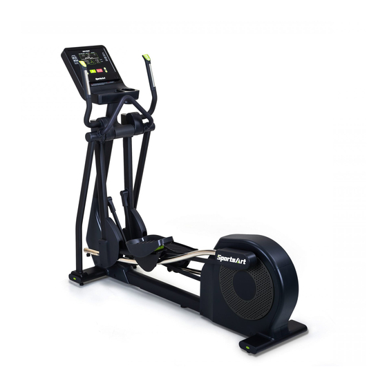
1. INTRODUCTION Congratulations on the purchase of a high quality SportsArt product, the E874 Elliptical trainer. Constructed of high quality materials and designed for years of reliable performance, this product was made for full commercial use. Before this product is assembled or operated, we recommend that you familiarize yourself with this manual. -
Page 4: Safety Precautions
2. SAFETY PRECAUTIONS This product was designed and built for optimum safety. However certain precautions apply during the use of this product. Please note the following safety precautions: ● To reduce the risk of personal injury, read and understand all the instructions before using this product. - Page 5 2. SAFETY PRECAUTIONS (CONT.) ● CAUTION : The heart rate system is for reference only, if you feel any pain or any abnormal feeling, please stop Exercise and consult your doctor immediately. ● Consult your physician before starting a workout or training program. It is recommended that you undergo a complete physical examination.
- Page 6 2. SAFETY PRECAUTIONS (CONT.) MARKINGS CAUTION: ● Read instruction manual before using. ● Do not let children on or near the product. WARRING: ● Heart rate monitoring system may be inaccurate. ● Over exercise may result in serious injury or death. ●...
-
Page 7: Warning Label Position
3. WARNING LABEL POSITION If you are in French-speaking areas in North America, display the warning label on console panel as shown below, or in an obvious location that is visible to the user. NOTE: The label is available exclusively in French-speaking areas in North America. -
Page 8: List Of Parts
4. LIST OF PARTS Assembly Parts Name Qty. No. Name Qty. A1 Main frame Front base cover A2 Stationary handlebar Left support tube A3 Console Right support tube A4 Left/right joint covers A10 Foot pedals A5 Left pedestal cover A11 Pedal bottom covers Outer link pedal arm A6 Right pedestal cover covers... - Page 9 4. LIST OF PARTS (CONTINUED) HARDWARE KIT Name Qty. Specification Notes Inner hex screw M10*P1.5*L20 Toothed lock washer D20*d10.2*t2.0 Secondary roller axle D9.96*L54 self-lubricating bushing Secondary roller Stride adjustment linkage cover Hex nut M10*P1.5 Stopper Ø30-30 Round shaped screw cap Mushroom top philips screw M4*L16 Round shaped screw cap...
- Page 10 4. LIST OF PARTS (CONTINUED) Pre-Installed Hardware Name Specification Notes Hex socket flat head cap screw M10*P1.5*L20 5/16”*L2-1/4” Inner hex screw Half tooth Flat washer D20*d8*t2.0 Mushroom top inner hex screw M8*P1.25*L15 Flat washer D17*d8.3*t2 Inner hex screw M6*P1.0*L15 Handlebar washer D20*d7*t2 Mushroom top inner hex screw M6*P1.0*L15...
-
Page 11: Assemble The Product
5. ASSEMBLE THE PRODUCT STEP 0 Preparation: Battery Instructions Before start using the elliptical trainer, remove the protective cover (a) and turn the battery switch on. 0-1 The unit can generate its own power. The battery provides backup power in case of insufficient power which may cause the unit fail to work. 0-2 After finishing assembly, be sure to turn on the battery switch. -
Page 12: Step 1 Install The Main Frame
STEP 1 Install the Main Frame (1) Remove all packaging material and place the main frame on the carton base. (2) Lift the console mast into upright position, and then tighten the following screws in sequence: screw (33) in (area D), screw (10) in (area A), and screws (10) in (area B,C). - Page 13 STEP 1 Install the Main Frame (Cont.) (5-1) (a) Slip the glide rail into the pedal carriage and lower swing arm. (b) Install the secondary roller (11) to the bottom of glide rail. (NOTE: Insert the axle toward inner side from outer side) (5-2) Insert the axle shaft into housing on the pedal arm, then tighten screw (34) to secure the assembly, and put the stride adjustment linkage cov- er (12) on.
- Page 14 STEP 1 Install the Main Frame (Cont.) (6-1) Insert left and right support tubes (A8)(A9) into the axle area and base, and loosely secure them into place with screws (35) (36) (6-2) Install the stationary handlebar (A2) to the left/right support tube and using screw (37) to secure the assembly.
-
Page 15: Step 2 Install The Console
STEP 2 Install the Console (1) Remove the following parts from the console(A3): anti-slip pad (51), screws (52)(53), and bottle holder (54). (2) Secure the console (A3) to the main frame (A1) with pre-installed screw (39). (3) Remove the rear cover (55), and then connect the cables of the main frame (A1) to the cables of the console (A3). -
Page 16: Step 3 Install The Outer Link Pedal Arm Covers
STEP 3 Install the Outer Link Pedal Arm Covers (1) Rotate the pedal arm to the position shown in the figure below, then put on cover B and rotate it 270 degrees clockwise. (2) Snap cover B and cover C together, and rotate the pedal arm until (area A) is easily accessed, then tighten screws (16)(17). -
Page 17: Step 4 Install The Front Base Cover
STEP 4 Install the Front Base Cover Secure left/right pedestal cover(A5)(A6) to the main frame using screw (15), then put on the round shaped screw cap (15) and the front base cover (A7). NOTE: Install the ground wire first before putting the front base cover on. -
Page 18: Step 5 Install The Pedals
STEP 5 Install the Pedals (1) Secure the pedal bottom cover (A11) to the main frame using screws (40), and then put on the round shaped screw cap (14). (2) Pull up part A, and then secure the foot pedal (A10) onto its mount on the pedal carriage (A1) using screw (41). -
Page 19: Step 6 Precautions When Installing The Pedals
STEP 6 Precautions When Installing the Pedals (1) Make sure the 2 nibs in (area L) are pushed into the holes on the foot pedal. (2) Tighten screws (m1), then push the 2 nibs in (area M) into the holes on the foot pedal. -
Page 20: Step 7 Move The Elliptical Trainer In Place
STEP 7 Move the Elliptical Trainer in Place Grip and lift the main base of the elliptical trainer, and then move it to the desired location. Be careful not to pinch your fingers when you put down the elliptical trainer. -
Page 21: Step 8 Level The Product
STEP 8 Level the Product (1) If your workout area is uneven, or if the rail assembly is slightly off the floor, loosen the locking nut at the back of the equipment and adjust the leveler until it is evenly balanced in contact with the floor, then tighten up the locking screw. -
Page 22: Step 9 Ground Wire Installation Instructions
STEP 9 Ground Wire Installation Instructions In order to avoid electric shock and current leaking, an additional ground wire is provided enclosed with the product. For safety reasons, be sure to connect the ground wire to the equipment. Assembly Instructions: Remove the pedestal covers (A5)(A6) and the front base cover (A7) first , and then thread the ground wire through the hole in the tube. -
Page 23: Understand The E874 Lcd Display
6. UNDERSTAND E874 LCD DISPLAY DISPLAY Overview In this chapter, you will learn how to use and set up the console of your elliptical trainer. Please read the entire manual prior to using the elliptical trainer to get the best exercise efficiency and enjoy your workout. DISPLAY Console Panel Description... -
Page 24: Display Windows Display
DISPLAY Window Display Description Display the data of your heart rate value. (Displayed when BOTH HANDS hold on the sensor.) Display your steps per minute (SPM). Display the messages or the illustration. Display the total time covered or the remaining time. Display your stride length. -
Page 25: Display Button Functions
DISPLAY Button Function Illustration Description The button has two functions : (1) Skip the user input, program selection, and start train- ing instantly. (2) After the parameter settings are complete, press the key to confirm your selection. Press to stop the workout progrqm Hold down to go back to start screen and reset it to factory settings Press this key to change stride length. - Page 26 DISPLAY Button Function (Cont.) Illustration Description Press this key to select one of an almost endless num- ber of randomly generated workout programs. Each key press, the console will randomly generate a different pro- gram. the notification LED will light on steadily. Press this key to enter FIT TEST mode.
-
Page 27: Operate The Product
7. OPERATE THE PRODUCT OPERATION Safe Operating Area (a) Safety clearance required as shown below. Do not allow people to be near this area when operating. (b) Noise emission under load is higher than without load. 600mm(23.6") -
Page 28: Operation Beware Of Moving Parts
OPERATION Beware of Moving Parts This product has moving parts that could be a danger to people and animals. During use, do not put hands or other objects into the stride adjustment slot, the rear cover opening, or other areas in which such action might present a hazard. -
Page 29: Operation Essential Functions Guide
OPERATION Essential Functions Guide LENGTH: Adjust the distance between two successive placements of the same foot. RESISTANCE: Adjust the weight or force you need to place on the pedals to push them. -
Page 30: Operation Safely Get On/Off
OPERATION Safely Get On/Off (a) Place your feet on floor and then hold the handles to steady self while stepping on the pedals as shown below. (b) Wait until pedals come to a complete stop and then hold onto handles for stability while carefully stepping off the elliptical. -
Page 31: Operation Proper Workout Position
OPERATION Proper Workout Position (a) Proper workout position for user is shown below. (b) Over exercising or improper workout form may result in serious injury. (c) User can hold onto handles for stability when getting on or getting off from the right/left side of the elliptical. (d) This product is intended for exercise arms and legs. -
Page 32: Operation Start Screen
OPERATION Start Screen Step on the pedal to start the machine. After started, you will hear the BEEP sound and see the start screen. OPERATION <GO> Mode GO mode is preset based on user 35 years old and weighs 75 kilograms (165 pounds). - Page 33 OPERATION User Setting Procedure (Continued) Parameter Window Description Setting a TIME workout goal: Select <TIME> as your workout goal, the <TIME> notification LED light will stay on and then proceed to time set- tings. The range is 5 - 300 minutes with the default of 30 minutes.
- Page 34 OPERATION User Setting Procedure (Continued) 3. AGE and WEIGHT Having finished the GOAL settings, proceed to AGE and WEIGHT setting. Refer to the following instructions for details. Parameter Window Description AGE Setting: The range is 10 - 99 years old with the default of 35 years old.
-
Page 35: Operation Workout Programs
OPERATION Workout Programs You can choose the desired program from the PROGRAM menu. The following information provide details about the programs. MANUAL: The general mode. Users can set their desired workout program.The resistance and stride length can be adjusted according to your own preference. - Page 36 OPERATION Workout Programs (Continued) RANDOM: The graphic pattern in RANDOM PROGRAM are generated randomly, and the illustration shows differently each time (1) Press the <RANDOM> key to select the desired graphic pattern. (2) During exercise, you can press the <RANDOM> key to change the graphic pattern.
- Page 37 OPERATION Workout Programs (Continued) WT LOSS , CARDIO: The programs take control of resistance, keeping your heart rate within the target zone. (1) Before entering this mode, press <WT LOSS/CARDIO> key to toggle between WT LOSS and CARDIO. The words “♥ 120” shown on the display represent WT LOSS mode, and the words “♥...
-
Page 38: Operation During Exercise
OPERATION During Exercise During exercise, you can switch to a different program using the same WORKOUT GOAL(TIME/DISTANCE/CALORIES) by pressing a different program key. Please note it is not allowed to switch directly in the situation as below, and the window will display the message ” SWITCHING NOT ALLOWED”. (1) During MANUAL、INTERVAL、PLATEAU、RANDOM、VARI-STRIDE 、CUSTOM HR、WT LOSS、CARDIO program, it cannot be switched to FIT TEST program. -
Page 39: Operation Idle Mode
OPERATION Idle Mode The machine will turn into power saving mode when there is no stepping on the pedal or not been operated to the buttons for 30 seconds, and the window will display “- - - -“ and continue to flash. To restart the machine, please step on the pedal or press any button to return to start screen. -
Page 40: Operation User Parameter Setting
OPERATION User Parameter Setting Hold the <RESISTANCE - > for 3 seconds to enter the user parameter setting procedures; press the <STOP> key at any time to return to the start screen. Please refer to the following setting procedures: (1) Metric System / Imperial Units Setting The window will display KM or MILE, press <LENGTH ▲/▼>... - Page 41 OPERATION User Parameter Setting (Continued) (6) Language Setting The window will show the options of the coutries, press <LENGTH ▲/▼> or <RESISTANCE +/- > key to select your language, then press <GO/ ENTER > to confirm and go to the next step. (7) Time Limit Setting The window will show the message of “TIME LIMIT”, press <LENGTH ▲/▼>...
-
Page 42: About Heart Rate Detection
8. ABOUT HEART RATE DETECTION Heart rate detection functions are selected at the time of purchase. Not every product has every type of heart rate detection. The following explains factors that influence the performance of two of the most common types of heart rate detection devices. -
Page 43: Guidelines For Exercise
9. GUIDELINES FOR EXERCISE HOW HARD SHOULD I EXERCISE? Studies show that to benefit from aerobic exercise, people need to maintain a certain heart rate during their workouts. Your heart rate training zone depends on your age and fitness level. The darkened area in the chart to the right represents the recommended heart rate training zone for people of various ages. -
Page 44: Maintenance
10. MAINTENANCE Maintenance topics are presented below in the following order: error mes- sages, lubrication of the shoulder area, lubrication of the stride area, glide rail cleaning, maintenance schedule, task list, one-year maintenance log, and electronics block diagram. MAINTENANCE Safety Precautions ●... -
Page 45: Maintenance Error Messages
MAINTENANCE Error Messages The window will show the error message when an unusual situation occurs on the machine. (Shown as illustration below, X is for the main code, Y is for the secondary code.) Error Code Description: Main Secondary Error message Note Code X Code Y... -
Page 46: Maintenance Messages
MAINTENANCE Messages SERVICE BATTERY The flashing light signals battery is near depletion (this signal appears when adjusting stride length, with a pedal speed less than 30 SPM),please charge the battery in one of the following ways: a. Charge the battery by pedaling. b. -
Page 47: Maintenance Lubrication Procedure
MAINTENANCE Lubrication Procedure (a) Push in at point A, and slide upward to remove the lubrication cover. (b) Press the stride up key to adjust the stride to its longest point. Note the grease fitting at area B. (c) Use an automobile grease gun with red lithium grease. Apply the grease to the nozzle on the product. -
Page 48: Maintenance Cleaning The Glide Rails
MAINTENANCE Cleaning the Glide Rails Follow the steps below to clean left and right glide rails on a daily basis: (a) Use a clean, lint-free cloth to wipe dust and debris off the glide rails. (b) Test the glide rails to ensure they move easily and smoothly. (c) Repeat steps (a) and (b) two or three times to ensure smooth movement. -
Page 49: Maintenance Schedule
MAINTENANCE Schedule Area Week Month Quarter Year Notes Exterior Cleanliness inspection ● Inspect and secure loose Screws ● parts Wipe away dirt and Glide rail ● debris. Rollers Apply silicone lubricant.. ● Stride motor Apply bearing grease ● Lubricate with original Cushion ●... -
Page 50: Accessories
11. ACCESSORIES ACCESSORIES Standard USB PORT 1. Provides up to 5V, 0.5A of power for charging 2. Let you update all required software drivers for the product. CSAFE PORT Compatible with CSAFE (Communications Specification for Fitness Equip ment) Protocol. *The figure below is for reference purposes only. QR code and NFC tag 1. -
Page 51: Accessories Option
ACCESSORIES Option SA WELL+ Member System This is designed specially by SportsArt to assist the user in managing their workout history. There are three ways to get connected with the member site: 1. Using a smartphone, connect to the unit via Bluetooth/WIFI and use the SA WELL+ App. - Page 52 ACCESSORIES Option (Continued) TV Mount Bracket...
-
Page 53: Appendixes
12. APPENDIXES APPENDIX Specifications Model E874 L : 2085 mm (82”) Dimensions W : 680 mm (26.8”) H : 1765 mm (69.5”) Overall Weight 151 kg (333 lbs) Maximum User 205 kg (450 lbs) Weight Power Requirement Self-generating... -
Page 54: Appendixes Electronics Block Diagram
APPENDIX Electronics Block Diagram HTR Board SA WELL T674 V886 SA WELL+ Key Board Option Key Board Connection key SA WELL Board Control Board USB Board USB Board HRC Board RESISTANCE(Right) LENGTH(Left) Stepper Motor Contact HTR plates Drive Board SG Steel Wheels and +... -
Page 55: Appendixes Exploded Diagrams
APPENDIX Exploded Diagrams Note: We reserve the right to revise the following diagrams at any time without notice to notify any person of such revisions. Please visit our official website www.gosportsart.com for the latest version. -
Page 56: Appendixes Disassembly
APPENDIX Disassembly (a) Main Frame (b) Lift Motor Assembly (c) Front Base Cover... - Page 57 Your Authorized Distributor...
Need help?
Do you have a question about the ECO-NATURAL Elite E874 and is the answer not in the manual?
Questions and answers