
Subscribe to Our Youtube Channel
Related Manuals for Avaya G150


Summary of Contents for Avaya G150
- Page 1 Installation and Configuration of the G150 Media Gateway 03-300395 Issue 1 June 2005...
- Page 2 • System administration documents Warranty • Security documents Avaya Inc. provides a limited warranty on this product. Refer to your • Hardware-/software-based security tools sales agreement to establish the terms of the limited warranty. In • Shared information between you and your peers addition, Avaya’s standard warranty language as well as information...
- Page 3 04DU9-DN 6.0Y RJ48C • A reorder tone is received. Avaya attests that this registered equipment is capable of providing users 04DU9-IKN 6.0Y RJ48C access to interstate providers of operator services through the use of access codes. Modification of this equipment by call aggregators to block 04DU9-ISN 6.0Y...
- Page 4 Contact the state public utility commission, public service E-mail: totalware@gwsmail.com commission or corporation commission for information. For the most current versions of documentation, go to the Avaya support This equipment, if it uses a telephone receiver, is hearing aid compatible. Web site: http://www.avaya.com/support.
-
Page 5: Table Of Contents
G150 Models ........ - Page 6 Functional Ground ....... . . Installing a New G150 System ......
- Page 7 G150 Media Gateway Overview ......G150 WAN Considerations ......
- Page 8 Addressing Messages Sent From Voicemail Pro ....Mailbox Mapping via G150 Manager ..... . .
- Page 9 Telephone Installation ....... . . Connecting and Testing G150 Telephones ....
- Page 10 G150 Configuration Information ......G150 Server Status ....... .
- Page 11 Contents Host ......... State .
- Page 12 Contents 12 Installation and Configuration of the G150 Media Gateway...
-
Page 13: About This Book
About This Book Overview This document provides procedures to install and configure an Avaya G150 Media Gateway controlled by an Avaya S8300, S8500, S8700/S8710, G3si or G3csi Media Server. It also includes information on connecting telephones and adjuncts to the G150. This document is intended for use after a Communication Manager 2.2 has been installed and configured with... -
Page 14: Conventions
About This Book Read Chapter 1: Installing Hardware for the G150 Media Gateway for instructions on installing and cabling the hardware. Read Chapter 5: G150 Media GatewayTelephone Support if you need to install phones or adjuncts. interruptible Power Supply (UPS), Universal Serial Bus (USB) Modems, and other adjuncts. -
Page 15: Terminology
Avaya Communication Manager is the application that provides call control and the Avaya telephony feature set. This application was referred to as MultiVantage Software or as Avaya Call Processing (ACP) in previous releases. The term Multivantage is still used in some CLI commands and in the Web interface. -
Page 16: User Input
Internet, and a copy of Acrobat Reader must be installed on your personal computer. Avaya makes every effort to ensure that the information in this book is complete and accurate. However, information can change after we publish this book. Therefore, the Avaya Web site might also contain new product information and updates to the information in this book. -
Page 17: Downloading This Book
Downloading this book To download the latest version of this book: 1. Access the Avaya web site at http://support.avaya.com. 2. On the left side of the page, click Product Documentation. 3. The system displays the Welcome to Product Documentation page. -
Page 18: Related Resources
The CD, Documentation for Avaya Communication Manager, Media Gateways and Servers, 03-300151, contains a comprehensive library of documents. For a summary of what is new in the June 2004 release of Avaya Communication Manager, see Highlights of Avaya Communication Manager, 555-245-704. -
Page 19: Trademarks
Trademarks All trademarks identified by the ® or ™ are registered trademarks or trademarks, respectively, of Avaya Inc. All other trademarks are the property of their respective owners. Ordering Documentation In addition to this book, other description, installation, maintenance, and administration books, and documentation library CDs, are available. - Page 20 About This Book 20 Installation and Configuration of the G150 Media Gateway...
-
Page 21: Chapter 1: Installing Hardware For The G150 Media Gateway
Planning and implementation personnel have conducted preliminary inspections of the site and of the other equipment to assure that the G150 solution will operate at its full potential. A data network readiness assessment has been completed to assure that the solution will function optimally within the customer's network. -
Page 22: Site Verification
G150 Gateway Capacity The G150 Media Gateway is supported with Avaya Communication Manager release 2.2 on the Media Servers listed in the table below. This table also outlines the gateway capacity for each media server. -
Page 23: Port Capacity
Signaling Group Capacity The Communication Manager switch software supports IP signaling group for each administered G150 gateway as follows: All analog trunks in that gateway that are administered and enabled appear as a group of "virtual" managed 64 Kbps trunk group members. -
Page 24: G150 Models
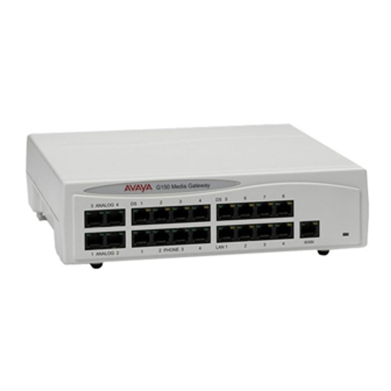
The G150 Media Gateway is supplied in the following models (each model is available in two versions to support either North American or International CO trunks): G150 2T + 4A (4 VoIP): Two Analog Trunks + 4 analog telephones + 4 VoIP compressors. - North America version - SAP code: 700343569... - Page 25 DTE port Audio port (not used) External O/P socket (not used) Figure 1: G150 4T + 4A + DS (16 VoIP) front view Port connections DS Ports: Not currently supported on the G150. Analog Trunk Ports: These ports are used for connection to standard analog trunks (loop start).
-
Page 26: G150 2T + 4A (4 Voip)
WAN Port: This is a 10/100Mbs Ethernet LAN port for connection to an IP routed WAN (e.g. DSL). Within the configuration software application (Manager), this port is referred to as LAN2. Cables G150 is supplied with one red CAT 5E cable. For Port Pinouts and Cables, refer to Appendix A: Technical Data. - Page 27 IP telephones (Avaya 4600 IP series). LAN ports allow information relating to incoming and outgoing telephone calls to be forwarded to PC based applications. They also provide access to the router functionality/configuration of the G150 platform for both data and Voice over IP (VoIP) calls. Within the configuration software application (Manager), these ports are referred to as LAN1.
-
Page 28: Back Panel Of The G150 (All Models)
A: Technical Data. Back Panel of the G150 (all models) All models of the G150 have the same configuration when viewing the back of the control unit. Figure 3: G150 back view Connections External O/P Socket: Not used with the G150. -
Page 29: Wan Interface Cards
BRI and T1/ISDN PRI. The local serving PSTN provider may offer one or the other of these interfaces in the given country of destination for this gateway. The WAN slot in the back panel of the G150 supports voice/data PSTN WAN interface of the following types:... - Page 30 DDI/DID service. G150 WAN Expansion Card The WAN expansion card is fitted to the G150 to provide a single WAN connection (X21, V35 or V24 via a 37-way D-type socket). Line speeds up to and including 2Mbps are supported on the interface.
-
Page 31: Using The Pcmcia Slot For Wireless Access (For Data Applications)
ISDN 2 (NI2) signalling modes. Using the PCMCIA slot for Wireless Access (for data applications) To use the G150 as a wireless access point, the G150 must be fitted with a Wireless LAN card and the Wireless LAN Access Point license key. -
Page 32: Quality Of Service (Qos)
<1%) Quality of Service (QoS) The G150 supports two IP routing queues on each of its WAN ports (Ethernet WAN on the front panel and the optional WAN interface on the back panel). One routing queue is dedicated to Voice Traffic, the second to any other data. Voice traffic and signaling can be independently marked using Differentiated Services. -
Page 33: Typical Configurations
DiffServe Settings for VoIP Calls Chapter 3. Typical Configurations The following sections illustrate two typical scenarios for usage of the ports on the G150. These are configuration examples only and are intended to demonstrate the flexibility of the G150. Sample Small Branch Office Setup... -
Page 34: A Sample Medium Branch Office
Connectivity example for a medium-sized branch office: 2 analog trunks 1 IP WAN connection 2 fax machines 6 IP phones Workgroup switch for data & voice devices Voicemail at company HQ 34 Installation and Configuration of the G150 Media Gateway... - Page 35 3rd party LAN switch with QoS 6 IP phones (each with 1151B1 PoE PSU) Capacity for 10 additional IP phones 8 DS ports for future use. Not currently supported on the G150. Figure 5: Sample of a Medium Branch Office Setup Issue 1 June 2005...
-
Page 36: Preparing For Installation
Installing Hardware for the G150 Media Gateway Preparing for Installation This section reviews the requirements for installing an G150 system. You must meet these requirements for the system to operate safely and in the intended manner. This section covers : Tools &... -
Page 37: Space Requirements
Width : 255mm (10 inches) Depth : 235mm (9.3 inches) Where a G150 is free standing, allow a minimum clearance of 62mm (2.5 inches) either side for cable trunking. Check there is suitable lighting for installation, system programming and future maintenance. -
Page 38: Power Supply Requirements
They may explode. Check with local codes for possible special disposal instructions. Power Supply Requirements G150 should only be connected to a clean power supply or to a UPS with 3-pin connectors including earth. CAUTION: The Lump-in-Line PSUs supplied with each G150 module must only be CAUTION: connected to a 50/60Hz, 100-240V power source. -
Page 39: Functional Ground
1. Use a 3.5mm Jack Plug (not supplied with kit) fitted with a suitable length of #14 AWG (minimum) solid insulated cable. The sleeve must not be green/yellow. 2. Insert this Jack Plug into the Functional Ground Jack Socket (in the back of the G150 Media Gateway). -
Page 40: G150 Shelf/Wall Mounting
G150 Shelf/Wall Mounting below. 6. Connect your PC LAN Port to one of the LAN Ports on the front of an G150 using a LAN Cable. 7. Switch on the ac mains supply. 8. The Manager software (provided on the Administrator CD) can now be installed on the PC. - Page 41 2. Fit the Z-bracket (item 2 below) onto the base of the unit using the M3 Plastite self tapping screw supplied. 3. Slide the G150 unit onto the two screws, locating them into the two retaining slots (item 1 below).
-
Page 42: Installation Of Integral Modules
Installing Hardware for the G150 Media Gateway Installation of Integral Modules A G150 can be fitted with a WAN module, a quad BRI module or a PRI/T1 module. In addition, either or both the optional PCMCIA cards (Memory and/or Wireless LAN) can be fitted. All items... - Page 43 Installing a New G150 System Figure 8: Installing Integral Modules You have now completed the initial hardware installation of the G150 Media Gateway. Issue 1 June 2005...
- Page 44 Installing Hardware for the G150 Media Gateway 44 Installation and Configuration of the G150 Media Gateway...
-
Page 45: Chapter 2: Communication Manager Administration For The Avaya G150 Media Gateway
S8300, S8500, S8700, or S8710 Media Server) must be configured, in accordance with the Communication Manager Remote Office Feature group, to recognize, communicate with, and control the Avaya G150 Media Gateway. Use the following instructions to help you configure and administer the G150 Media Gateway within Communication Manager software. -
Page 46: Administer Customer Options
Instructions Verify that the following fields are administered on the System Parameters Customer Options screen. An Avaya representative must administer these fields or install a license file that enables the options identified by these fields. 1. Type display system-parameters customer-options and press ENTER to display the screen. - Page 47 Maximum Ports Maximum Administered Remote Office Trunks: Total number of trunk group members for all G150 media Gateways supported by this media server (a single B-channel of a T1 or BRI is a trunk group member). Maximum Concurrently Administered Remote Office Stations: Total number of stations (analog) for all G150 Media Gateways supported by this media server.
- Page 48 Communication Manager Administration for the Avaya G150 Media Gateway Figure 11: Optional Features screen (page 4) display system-parameters customer-options Page 4 of OPTIONAL FEATURES Emergency Access to Attendant? y IP Stations? y Enable ‘dadmin’ Login? y Internet Protocol (IP) PNC? y...
- Page 49 Administer customer options Figure 12: Optional Features screen (page 5) display system-parameters customer-options page 5 of x OPTIONAL FEATURES Multinational Locations? Station and Trunk MSP? n Multiple Level Precedence and Preemption? Station as Virtual Extension? n Multiple Locations? y Survivable Remote Processor? n System Management Data Transfer? n Personal Station Access (PSA)? y Posted Messages? n...
-
Page 50: Direct Ip-Ip Audio And Ip Hairpinning
Communication Manager Administration for the Avaya G150 Media Gateway 8. Verify data for the following fields: Product ID: IP_ROMax. Limit: Total number of remote office stations for IP_ROMax. Note: If these values are not large enough, ou may have to request a new RFA license Note: file to increase them. -
Page 51: Administer Ip Boards
3. Set the IP Audio Hairpinning field to y (yes) to enable or n (no) to disable hairpinning system-wide. However, see the following note. Note: For the G150 Media Gateway, IP Audio Hairpinning should be turned off for Note: optimal performance. However, if most gateways in the Communication Manager’s configuration, such as G700 or G350 Media Gateways, support... - Page 52 Communication Manager Administration for the Avaya G150 Media Gateway Figure 15: Circuit Packs screen (page 1) display circuit-packs Page 1 of 5 Circuit Packs Cabinet: 1 Carrier: A Cabinet Layout: five-carrier Carrier Type: port Slot Code SF Mode Name Slot Code SF Mode Name...
- Page 53 2. Complete the following fields: Name: Assign a unique name to the G150 Media Gateway. Note: This name must match exactly the name of the G150 Media Gateway as entered Note: on the System | SO Gateway | Gateway Name configuration in the G150 Manager.
- Page 54 Communication Manager Administration for the Avaya G150 Media Gateway Figure 17: IP Interfaces screen (DEFINITY Servers and S8500, S8700, and S8710 Media Servers) list ip-interface Page 1 of 4 IP INTERFACES ON Type Slot Code Sfx Node Name Subnet Mask...
- Page 55 For an S8300 Media Server only, verify that the Processor (PROCR) is assigned in the Net Rgn (Network Regions) field for optimal support of G150 Media Gateway units. Ideally, the resources are in the same network region as the G150 Media Gateway.
- Page 56 Communication Manager Administration for the Avaya G150 Media Gateway Administer Ethernet data module Note: For an S8300 Media Server, skip this procedure. This procedure does not apply. Note: You need to add an Ethernet data module on the Data Module screen for the C-LAN connection if one is not already present.
-
Page 57: Administer Codecs
Calculating the amount of bandwidth that voice-encoding-over-IP requires is a little more complex. The G150 Media Gateway offers a choice of CODECs from the G.711, G.723 (not recommended), and G.729 family at the point of call registration. The media server selects a particular CODEC at the point of call establishment. - Page 58 Communication Manager Administration for the Avaya G150 Media Gateway Note: The number of bits of payload per packet depends on the packet size, but is Note: independent of the sizes of the individual frames contained in that packet. For example, a packet size of 60 ms could be referring to six 10 ms frames per packet, or three 20 ms frames per packet, or two 30 ms frames per packet, etc.
-
Page 59: Administer Network Regions
Administer network regions 2. Administer a list of audio CODECs, in preference order, that are supported by the G150 Media Gateway. Supported codecs are: G.711MU (G.711 Mu-law) G.711A (G.711 A-law) G.723 (supported, but not recommended) G.729a (the commonly used codec between G150 Media Gateways) 3. -
Page 60: Instructions
Communication Manager Administration for the Avaya G150 Media Gateway Instructions To administer the network region for both the server’s central gateway and the G150 Media Gateway, do the following: 1. Type change ip-network-region <number> and press ENTER to display the IP Network Regions screen. - Page 61 IP Audio Hairpinning: Type y (yes) to enable or n (no) to disable hairpinning between endpoints in the server’s region. Though the G150 Media Gateway performs better without hairpinning, there may be many other gateways or devices in the network region that can benefit from hairpinning.
- Page 62 Communication Manager Administration for the Avaya G150 Media Gateway Figure 23: IP Network Region screen (page 3), example for server change ip-network-region 1 Page 3 of 19 Inter Network Region Connection Management src dst codec direct Dynamic CAC rgn rgn...
- Page 63 RSVP unreserved (BBE) PHB Value: 40 7. On the IP Network Region screen, complete the following fields: Name: Assign a unique name to the network region for the G150 Media Gateway. CODEC Set: Assign the CODEC set for the G150 Media Gateway associated with this Network Region.
- Page 64 Sharing of resources between or among network regions is allowed only if you Note: make an entry specifying the CODEC set to be used. Figure 25: IP Network Region screen (page 3), example for G150 change ip-network-region 3 Page 3 of 19...
-
Page 65: Udp Port Assignments
The G150 Media Gateway uses a single block of UDP ports for audio connections. The default block starts at 49152. For a given G150 station or trunk port, one UDP port is used for RTP and the next consecutive UDP port is used for RTCP. For example, with the default block setting, analog trunk 2 uses 49154 for the RTP/UDP connection and 49155 for the RTCP/UDP connection. - Page 66 Communication Manager Administration for the Avaya G150 Media Gateway Table 8: Port Assignments for Analog Stations (no BRI or PRI WAN card) Trunk/Extn Type RAS UDP Q.931 RTP UDP RTCP Port Port Port UDP Port Analog Station 6001 7001 49160...
-
Page 67: Administer Multiple Locations
Administer multiple locations The Locations screen allows you to assign time zone and daylight saving rule parameters by location. Since a G150 Media Gateway will most likely be remotely located from the media server, establish location parameters for each G150 region. - Page 68 Attd FAC: Type an Attendant FAC for attendant access if the number should be different than the system-wide attendant FAC. Loc. Parms: Type the number of a set of location parameters if the G150 requires unique parameters such as loss parameters.
-
Page 69: Administer Remote Office
Phone: xxx-yyy-zzz _______________________________ 2. Complete the following fields: Node Name: Assign a node name to the Avaya G150 Media Gateway. This name must correspond to the node name used on the IP Node Names screen. Note: This name must also match exactly the name of the G150 Media Gateway as... - Page 70 Communication Manager Administration for the Avaya G150 Media Gateway 3. Press ENTER to effect the changes. 4. Type status remote-office n and press ENTER to verify the addition of the G150 Media Gateway. The system displays the Remote Office Status screen.
-
Page 71: Set Up A Signaling Group And Digital Trunk Group
H.323 trunk or signaling group between the G150 Media Gateway and the media server. Each G150 Media Gateway has its own listening port and signaling group for the digital trunks (T1 or BRI). Set up a new signaling group and trunk group administered for H.323 signaling. - Page 72 Chapter 3. Near-end Listen Port: Type a port number in the 5000-9999 range. Far-end Listen Port: Type 7001. This is the dedicated TCP port in the G150 Media Gateway. For an explanation of the TCP port usage, please refer to...
- Page 73 Set up a signaling group and digital trunk group Direct IP-IP audio connections: Type y to enable IP call shuffling. IP Audio Hairpinning: Type n to disable. This setting prevents hairpinning for calls using this signaling group, even if the server’s system parameters and the network regions have been enabled for hairpinning.
- Page 74 Because this is an H.323 signaling group, the media server cannot tell that this ultimately terminates in a digital trunk (for instance, does not know if this is PRI signaling or in-band signaling). Loss group 17 is the correct loss group for digital trunks on the G150 Media Gateway.
-
Page 75: Set Up A Signaling Group And An Analog Trunk Group
PSTN network, both of the circuit switched channels utilized are part of this one signaling group. Each G150 Media Gateway that uses one or both of its central office loop-start analog trunks has a listen port, a signaling group, and a trunk group that are unique to those analog trunks, and separate from the listen port, signaling group, and trunk group used by the T1 digital trunk. - Page 76 Far-end Node Name: Type the node name assigned to the remote office. Near-end Listen Port: Type a port number in the 5000-9999 range. Far-end Listen Port: Type 7000. This is the dedicated TCP port in the G150 Media Gateway. Note: The far-end port must be 7000.
- Page 77 Because this is an H.323 signaling group, the media server cannot tell that this ultimately terminates in an analog trunk. Loss group 7 is the correct loss group for analog trunks on the G150 Media Gateway. 3. Go to the Group Member Assignments screen to associate the trunk group with the signaling group.
-
Page 78: Administer Loss Plan
Sig Grp: Assign the number of the signaling group that provides the signaling channel for this trunk group. Either two trunks (for the G150 2T + 4A model) or four trunks (for the G150 4T+4A+8DS model) may be designated in this group. -
Page 79: Add Phones To Remote Office Location
G150 Manager. See Extension Numbering within G150 Setting up Users Chapter 3 for details on configuring this information on the G150 Manager interface. Add an analog telephone 1. Type add station <extension number> and press ENTER to display the Station screen. - Page 80 Type: Assign the set type associated with the terminal. Port: Type x. Security Code: Assign a security code/password that is used to validate G150 Media Gateway registration using this extension. The maximum length of the security code/ password is seven digits.
- Page 81 5. In the IP Audio Hairpinning field, type n to disable hairpinning for optimal performance with the G150. This setting prevents hairpinning for calls using this telephone, even if the the server’s system parameters and the network regions have been enabled for hairpinning.
- Page 82 Name: Identify the phone for your records. Security Code: Match the password set up on the G150 Media Gateway administration. Survivable GK Node Name: Type the name of the G150 Media Gateway with which this phone is co-located. Check the IP Node Names screen for names.
-
Page 83: Administer Features And Codes
5. In the IP Audio Hairpinning field, type n to disable hairpinning for optimal performance with the G150. This setting prevents hairpinning for calls using this telephone, even if the the server’s system parameters and the network regions have been enabled for hairpinning. - Page 84 Communication Manager Administration for the Avaya G150 Media Gateway 84 Installation and Configuration of the G150 Media Gateway...
-
Page 85: Chapter 3: Configuring The G150 Media Gateway With Manager
In the event that the connection to Communication Manager becomes unavailable for any reason - WAN, LAN or equipment failure - the G150 attempts to register against an alternative CLAN or Processor CLANs. If no alternative gatekeeper is available, the G150 changes from sub-tending to survivable mode. -
Page 86: G150 Wan Considerations
The G150 is connected to a Media Server running Communication Manager using an IP data connection over a WAN. The WAN can be connected directly to the G150 or by a third party router where data infrastructure already exists or the appropriate WAN interface is not available on the G150 itself. -
Page 87: Quick Reference Install And Configuration
Quick Reference Install and Configuration G150 is a flexible product that can be set up and configured in several ways, depending on network requirements, IP phone usage, etc. However, there are bare minimum installation and configuration steps required to get G150 functional. These steps are: Configure Communication Manager to communicate with the G150. -
Page 88: The Manager Application Software
G150 system. The G150 can be connected in one of two ways; either directly to a PC or as part of a LAN. Both methods use a G150 Cat. 5E patch cable connected between one of the LAN ports on the front of the G150 and the PC/LAN. -
Page 89: Installing The Manager Software
Installing the Manager Software Before any aspects of the G150 can be configured, a configuration software application called Manager must be installed on the PC that is connected to the G150. The Manager software is available from the Administrator CD. -
Page 90: Editing A Configuration
Configuring the G150 Media Gateway with Manager Editing a Configuration Manager displays the G150’s configuration as a series of icons in two panels, as displayed in Figure Figure 39: Manager Configuration Window The left-hand panel contains a Configuration Tree, with icons used to group different types of configuration entries. -
Page 91: Saving A Configuration
Manager. There are two ways to save a configuration, via a system merge or a full reboot of the G150 control unit. Manager tracks the changes made to the configuration so that if all the changes made can be merged, then the option for merging (Merge Config) will automatically be selected and if a reboot is required, When Free will be selected. - Page 92 Immediately - Reboots the Control Unit immediately and will cut off any calls in progress. When Free - Reboots the G150 when the system is free (no calls in progress). The following options are only available with When Free selection:...
-
Page 93: Update Manager Account Information
None - Does not send any configuration to the G150. 3. If you did not enter a system password when you received the configuration, then a password MUST be entered at this point to send the configuration to the G150. 4. Select OK. -
Page 94: Creating Additional Operator Accounts
4. On the Operator tab: Name: Enter the user name in which this operator will log onto Manager. Password/Confirm Password: Enter the password from which this operator will use to log onto Manager. 94 Installation and Configuration of the G150 Media Gateway... -
Page 95: Specify An Ip Address To The G150
G150. The constraint of 10 IP addresses maximum is because each install of a Manager application can remember the IP addresses of only 10 G150 systems at any one time. If the PC has two LAN connections, then it is necessary to set the IP address to the broadcast address of the LAN, eg. - Page 96 Configuring the G150 Media Gateway with Manager Figure 43: Preferences Edit 3. Enter the IP address of the G150 or a more general broadcast address into the IP address field. By default, the IP address of 192.168.42.1 is assigned to the G150. If this default static IP address is not acceptable because of the customer’s network addressing scheme, obtain...
-
Page 97: Change System Password
The file extension used for backup configuration files. 5. Click OK. 6. The newly entered IP address is now specified for the G150. This can be confirmed by the display of the IP address on the Manager’s title bar as show in... - Page 98 Password fields. Enter the new password in to both fields. Password must be at least 4 characters long and the system is case sensitive. Make note of this new password in a safe location. 98 Installation and Configuration of the G150 Media Gateway...
-
Page 99: Configure G150 For The Communication Manager
The Receiving config from dialog box appears displaying the IP address of the G150. Enter the G150 system password. 2. Click System from the Configuration Tree and double click the G150 configuration on the right hand side of the display window. -
Page 100: Gatekeeper Registration
Configuring the G150 Media Gateway with Manager Figure 47: Manager SO Gateway screen 3. Click the SO Gateway tab. In the Gateway Name field, enter the name of your G150 Media Gateway. This name MUST match all of the following fields within the Communication... - Page 101 Communication Manager configuration in the node names | CLANx | ip address field. G150 enters its own IP address as the last one on the list, thus assigning the G150 as the final fallback gatekeeper. To enter a Gatekeeper IP address: 1.
-
Page 102: Ras Udp Port Configuration
Save when ready. If updates of the manually entered Gatekeepers are required, the Manager application must be used. If the Alternate Gatekeeper List is updated, the G150 must be restarted for the updated list to be captured. -
Page 103: Time Settings For Interaction Between G150 And Communication Manager
During this time, no call activity is allowed on the G150. Because of this lack of call activity, the Host Lookup Time should not be set for an extended amount of time. On the other hand,... -
Page 104: Trunk Configuration
Trunk Configuration Incoming Trunk Call with No DID (DDI) Information When an incoming trunk call is received by the G150 with no DDI information, a default Communication Manager extension number is dialed. The default extension number is 1001. This default extension number for all trunks can be configured by doing the following: 1. -
Page 105: Diffserve Settings For Voip Calls
(such as routers) on the network that effect Quality of Service. These settings effect VoIP calls when the G150 is in both subtending and survivable mode. The following table shows the configurable fields on the G150 and their corresponding configuration on Communication... -
Page 106: Analog Trunk Configuration
To configure settings on the analog trunk: 1. Click to receive a configuration form. The Receiving Config from dialog box appears displaying the IP address of the G150. Enter the G150 system password. 106 Installation and Configuration of the G150 Media Gateway... - Page 107 System | SO Gateway tab is used instead. When an incoming trunk call is received by the G150 with no DDI information, a default Communication Manager extension number is dialed. Enter that extension number here.
- Page 108 This direction setting MUST match the associated trunk group’s Direction setting on Communication Manager. Bearer: Default = Any Sets the type of traffic carried by the line (Voice, Data or Any). 108 Installation and Configuration of the G150 Media Gateway...
- Page 109 Modem Enabled: Default = Off (only available on the first Analog trunk) The first analog trunk on G150 can be set to modem operation (V.32 with V42 error correction). This allows the receipt of incoming modem calls for system maintenance operation.
-
Page 110: Quad Bri Trunk Configuration
Control of trunks in sub-tending mode is driven by Communication Manager, with the exception of certain low level BRI trunk parameters, which are configurable via Manager. On this same configuration, the Prefix and Group options apply to the G150 in survivable mode only. To configure the Quad BRI Trunk: 1. - Page 111 Channel dialog box for that particular channel displays the following configuration fields: - Incoming Group & Outgoing Group: Default = 0 *These settings apply to G150 in survivable mode only. A group can contain multiple lines and channels. Short codes and Incoming Call Routes can indicate which group they should use.
- Page 112 ISDN as an "international number" this prefix is added, eg. 441923000000 is converted to 00441923000000. 4. The Clock Quality configuration field within the Advanced tab applies to the G150 in both sub-tending and survivable mode. Clock Quality: Default = Network Sets whether the Control Unit takes its clock source from the network, use the network as a fallback source or not as a clock source.
-
Page 113: Pri Trunk Configuration
Trunk Configuration PRI Trunk Configuration G150 only supports T1 PRI trunks, i.e. up to 24 channels. Control of trunks in sub-tending mode is driven by Communication Manager, with the exception of certain low level PRI trunk parameters, which are configurable via Manager. The PRI configuration on Manager is used to configure PRI lines provided by T1 PRI card installed in the G150. - Page 114 Select the PSTN service provider (AT&T, Sprint, WorldCom or Local Telco). Prefix: *Applies to Survivable Mode only; Default = Blank *This setting applies to G150 in survivable mode only. Enter the number to prefix to all incoming numbers for last number redial. This is useful if all users must dial a prefix to access an outside line.
- Page 115 - Click OK on the Edit Channel window. 4. Click OK if any updates have been made. 5. Within the Advanced tab, the following configuration fields apply to the G150 in both sub-tending and survivable mode: Test Number: Used to remember the external telephone number of this line to assist with loop-back testing.
-
Page 116: T1 Trunk (In-Band Signaling) Configuration
T1 trunk parameters, which are configurable via Manager. The T1 configuration on Manager is used to configure T1 lines provided by a T1 PRI card installed in the G150. On this same configuration, the Prefix and Group options apply to the G150 in survivable mode only. - Page 117 The order, 24 to 1 or 1 to 24, in which channels are allocated for outgoing calls. Prefix: Default = Blank *This setting applies to G150 in survivable mode only. Enter the number to prefix to all incoming numbers for callback. This is useful if all users must dial a prefix to access an outside line.
- Page 118 - Click OK on the Edit Channel window. 4. Click OK if any updates have been made. 5. Within the Advanced tab, the following configuration fields apply to the G150 in both sub-tending and survivable mode: Test Number: Used to remember the external telephone number of this line to assist with loop-back testing.
-
Page 119: Dial Plan Administration
In subtending mode, call routing/dial plan are driven by the Communication Manager. In survivable mode, the G150 becomes a gatekeeper and handles calls using its own local call routing/dial plan configuration. The local administration of the G150 provides a simple call routing plan that emulates those of the Communication Manager such that all station extensions and trunk access codes remain the same. -
Page 120: Extension Numbering Within G150
Configuring the G150 Media Gateway with Manager Extension Numbering within G150 By default, G150 creates a hunt group with extension number 200 (survivable mode use only) and then automatically numbers the analog phones from 201 upwards. You must alter the extension numbering of the analog phones to match their numbering on the Communication Manager dial plan. -
Page 121: Setting Up Users
Save when ready. Setting up Users Users on the G150 are recognized by the Communication Manager via H.323 RAS authentication procedures using extension number as an "alias" and using the password as the "encryption key". -
Page 122: Dial Plan Support In Survivable Mode
Manager Administration for the Avaya G150 Media Gateway for information on configuring Communication Manager. Dial Plan Support in Survivable Mode The G150 supports a survivable call routing/dial plan consisting of the following: Extension numbering Group membership Hunt Group mode Call routing... -
Page 123: Create An Incoming Call Route
Dial Plan Administration Create an Incoming Call Route To enable calls to be routed when the G150 goes into survivable mode, Incoming Call Routes must be configured. In survivable mode, DDI/DID is supported for all trunk types (Analog, BRI, PRI and T1). DDI/DID calls matching the numbering plan are routed directly to a numbered extension by the G150 Incoming Call Route configuration on Manager. -
Page 124: Hunt Group
This Hunt Group is configured in Group ring mode (by default); therefore, all incoming calls ring each extension simultaneously. Only this one hunt group is supported with the G150 in survivable mode. In subtending mode, Communication Manager settings determine hunt group operation. - Page 125 Dial Plan Administration Figure 58: Manager Hunt Group Configuration screen The following fields are available for updates: Extension: The extension number to be used by the Hunt Group. An extension number that does not conflict with an existing user’s extension number must be entered. No Answer Time (secs): Default = Blank The number of seconds an extension rings before the call is passed to another extension in the list.
-
Page 126: Snmp Traps
Save when ready. SNMP Traps G150 SNMP traps can be configured via the SNMP tab within the Manager System configuration form. Traps can be sent to two independent IP addresses, for applications where an end-user and maintainer both need to be notified of a fault. - Page 127 The Receiving Config from dialog box appears displaying the IP address of the G150. Enter the G150 system password. 2. Click System from the Configuration Tree and double click the G150 configuration on the right hand side of the display window.
-
Page 128: Connecting G150 To The Network & Communication Manager
Configuration without IP Phones If there are no IP phones connected locally to the G150 or any intentions of using IP phones in the future, LAN1 can be used to connect to the network. Once the necessary configuration on G150 and Communication Manager has been made, configure G150’s connection to the... -
Page 129: Configuration Options With Ip Phones
The G150 has the ability to manage the customer’s IP network through its integral DHCP server. The G150 can be configured to hold a pool of IP addresses for users on the Local Area Network. When a user’s PC is powered up, the G150 system will allocate an IP address for the duration of the user’s logon session. - Page 130 Sample G150 Network Configuration With IP phones plugged into the LAN ports on the front of the G150, the WAN port on the front of the G150 can be used to connect to the Communication Manager and configured via the LAN2 form on Manager.
- Page 131 The LAN segment LAN1 is configured with the IP address range of 192.168.42.x and G150’s address is set to 192.168.42.1. The LAN segment LAN2 is configured with the IP address range of 192.168.43.x, G150’s address is set to 192.168.43.1, and Router A’s address is set to 192.168.43.2.
- Page 132 Site A.) In this case, Router A can be configured to route with a single subnet - 192.168.42.x with subnet mask of 255.255.254.0 in this example. G150 can then split the subnet into two segments using Proxy ARP. An IP route must be configured in G150 for each LAN1 address and must have Proxy ARP enabled.
-
Page 133: Configuring Lan1
The Receiving Config from dialog box appears displaying the IP address of the G150. Enter the G150 system password. 2. Click System from the Configuration Tree and double click the G150 configuration on the right hand side of the display window. - Page 134 IP address MUST match that entered in the IP Node Names | IP Address field for the corresponding G150. If the G150 is acting as a DHCP server on LAN1, then this address will be the DHCP starting address. A static IP Address is recommended. If the default static IP address is not acceptable based on the customer’s addressing scheme, obtain an acceptable...
- Page 135 This is the Subnet mask used on LAN1. Dial In: This option allows the G150 to allocate IP addresses to PPP Dial In users only. It will not allocate IP addresses to local devices on this LAN. If this configuration is selected, please provide the following additional information: - IP Address: Default = 192.168.42.1...
-
Page 136: Configuring Lan2
With LAN1 configured as the DHCP server for devices connected to the LAN ports on the front of the G150, LAN2 can be configured to be a DHCP client or disabled (in which case it requires a static IP address). - Page 137 This is the Subnet mask used on LAN2. Dial In: This option allows the G150 to allocate IP addresses to PPP Dial In users only. It will NOT allocate IP addresses to local devices on this LAN. If this configuration is selected, please provide the following additional information: - IP Address: Default = 192.168.42.1...
-
Page 138: Configuring The Wan Expansion Card For Connection To The Communication Manager
9. Click OK. Editting the WAN port DO NOT create a new WAN Port, this is automatically detected by the G150. If a WAN Port is not displayed, connect the WAN cable, reboot the G150 and receive the configuration. The WAN Port configuration form should now be displayed. - Page 139 2. Click WANPort from the Configuration Tree. Double-click the WAN port to open the configuration window. If a WAN Port is not displayed, connect the WAN cable, reboot the G150 and receive the configuration. The WAN Port configuration form should now be displayed.
-
Page 140: Using Lan1 For Ip Phones And Connection To Communication Manager
Using LAN1 for IP Phones and Connection to Communication Manager If IP phones are used, they must be connected via the LAN ports on the front of the G150. One of these ports can also be used to connect to the network/Communication Manager. These ports are configured via the LAN1 tab on Manager’s System configuration form. - Page 141 G150 is a DHCP Server If G150 is acting as the DHCP server, it will assign its own IP address as the default gateway to all IP stations connected to it. Traffic intended for other subnets will be redirected to the true local router using ICMP redirect.
- Page 142 IP address MUST match that entered in the IP Node Names | IP Address field for the corresponding G150. If the G150 is acting as a DHCP server on LAN1, then this address will be the DHCP starting address. A static IP Address is recommended. If the default static IP address is not acceptable based on the customer’s addressing scheme, obtain an acceptable...
- Page 143 Using an External DHCP Server If another device (other then the G150) is acting as the DHCP server for LAN1, the 176 option needs to be added to that server. Avaya IP phones need the IP address of two H.323 Gatekeepers (Communication Manager and G150) and a TFTP server (for example a PC running Manager).
-
Page 144: Testing An Installation
G150 connected to the Communication Manager (sub-tending mode). Verificaton in Survivable Mode Prior to connecting the G150 to Communication Manager, plug the IP phones into the LAN ports on the front of the G150 and verify the following: Ensure all IP phones register with G150. -
Page 145: Using Shortcodes
TAC and FAC support and provide call barring options. For functioning in survivable mode, the G150 dial plan can be further administered on the gateway via the Manager application using the shortcode table. The short code tables can be configured system-wide, against individual users or against groups of users. -
Page 146: Short Code Characters
Time) before acting on the short code. Important: In the United States, this short code character MUST be used when the line Important: group for the short code contains PRI lines or T1 lines emulating analog lines. 146 Installation and Configuration of the G150 Media Gateway... -
Page 147: Telephone Number Characters
G150 is predefined with default feature access codes and trunk access codes. The system short codes in this table come as default with the G150 configuration when the system locale is set to enu (North America) in Manager’s System configuration form. -
Page 148: System Default Shortcodes For A G150 Set To A Uk Locale
System default shortcodes for a G150 set to a UK locale: The system short codes in this table come as default with the G150 configuration when the system locale is set to eng (United Kingdom) in Manager’s System configuration form. -
Page 149: Shortcode Features
*4000* "MAINTENANCE" RelayOn Connect/disconnect modem to/from first analogue trunk 2 of 2 Shortcode Features The following shortcode features are supported on the G150 in survivable mode: Busy Call Pickup Any Clear Call Dial Dial3K1 Dial56K Dial64K Dial Direct... -
Page 150: Sample Shortcode Setups
The following user short code dials the extension specified (extn. 201 in this example) the moment the user's handset it is picked up. Short Code: ?D Telephone Number: 201 Line Group ID: 0 Feature: DialExtn 150 Installation and Configuration of the G150 Media Gateway... -
Page 151: Modem Control Shortcode
If the system switches from suvivable to sub-tending mode while the modem is Note: switched On, it will remain On until G150 goes into survivable mode again or it is restarted, because short codes are only processed during survivable mode. -
Page 152: Mapping Communication Manager Features To G150
Configuring the G150 Media Gateway with Manager Mapping Communication Manager Features to G150 When configuring the G150, keep in mind that dial plan features configured on the Communication Manager also require provisioning on the G150 if they are to remain available to G150 users when the connection to Communication Manager is lost. - Page 153 Using Shortcodes Table 15: TAC and Short Code Communication Manager TAC Sample G150 Configuration (System Shortcode) *006 to dial out through PRI trunk (line number 2). Note: The 4 analog trunks are viewed as one group by Communication Manager for...
-
Page 154: Remote Access
Route. Remote Access Before leaving the customer’s site, it is a good idea to set up remote access to the G150 system for maintenance purposes. G150 provides Remote Access Server (RAS) functionality, allowing external users to dial into the local area network from modems, terminal adaptors and routers. - Page 155 Additional configuration (Bearer Capability) is available if necessary. 1. Click to receive a configuration form. The Receiving Config from dialog box appears displaying the IP address of the G150. Enter the G150 system password. 2. Click Incoming Call Route from the Configuration Tree. Issue 1 June 2005...
- Page 156 1. Click to receive a configuration form. The Receiving Config from dialog box appears displaying the IP address of the G150. Enter the G150 system password. 2. Click Line from the Configuration Tree. 3. Double-click the first analog line from the list of lines. The Analog Trunk configuration window is displayed.
-
Page 157: Remote Dial-Up Pc Setup
The steps above are sufficient for an incoming digital data connection. However, if the remote user has an IP address that is not in the same domain as the G150, then an IP Route is needed for outgoing return data. -
Page 158: Remote Access On An Analog Line
*4000* short code can be used to connect and disconnect the modem to/from the first analog line. The *4000* short code only works when the G150 is in survivable mode and from within the customer’s site. Thus, when the remote user needs to have the modem connected or disconnected, a call must be made to the customer’s site requesting that the *4000* short code... -
Page 159: Chapter 4: Voicemail For G150 Media Gateway
In sub-tending mode, all voicemail functionality is driven by the Communication Manager. In survivable mode, G150 can operate with Voicemail Pro to take messages on behalf of users and groups. When connection to an active Gatekeeper is established, Voicemail Pro forwards all messages to Communication Manager’s messaging solution - Modular Messaging 2.0,... -
Page 160: Network Requirements
- If directly connected and the PC card does not operate correctly; its settings may need to be manually set to operate with G150. This should be done according to the PC or network card manufacturer’s instructions. The G150 LAN port is full duplex with 10Mbps/100Mbps auto sensing. - Page 161 Figure 68: Windows InstallShield for Removing Voicemail Pro screen Remove Voicemail Pro by: 1. Open the Windows Control Panel. 2. Select Add/Remove Programs. 3. Select IP Office Voicemail Pro and click Add/Remove. 4. From the options offered select Remove and click Next. 5.
- Page 162 8. Select who should be allowed to use the Voicemail client after installation on the server PC. Selecting Anyone who uses this computer (all users) is recommended. 9. Click Next to continue. The following screen is displayed. 162 Installation and Configuration of the G150 Media Gateway...
- Page 163 Figure 71: Windows InstallShield Setup screen 10. Select ACM Gateway. 11. Click on Next. Figure 72: Windows InstallShield Account Name screen 12. Enter the User name and Password for the user account under which the Voicemail service should log on and run. The Browse button can be used to browse the available PC or network accounts.
- Page 164 Figure 73: Windows InstallShield Program Folder screen 14. Select the program folder into which icons for the Voicemail Pro components should be added. 15. Click Next. Figure 74: Windows InstallShiled File Copying screen 164 Installation and Configuration of the G150 Media Gateway...
- Page 165 16. A summary of the components that will be installed is shown. Check that this list is as expected. Under Speech Supported check that the languages required are shown. English is always listed in addition to the installation language selected. 17.
- Page 166 Voicemail for G150 Media Gateway 22. A screen displays requesting you to select to where the Voicemail Pro should forward messages when the G150 Media Gateway exits survivable mode and the messaging format to use. Message Networking/Interchange: Select this option if the interface to central messaging is via Message Networking or Interchange, ie.
- Page 167 Port Number: Enter the port number for the mail server (usually port 25 for SMTP). Server Requires Authentication: Enter any authentication option for the SMTP email account. If the SMTP mail server has authentication defined, then tick this option and provide the relevant information. Note: This configuration window is also available on the Voicemail Pro PC on the Note:...
-
Page 168: Starting The Voicemail Pro Server
Starting the Voicemail Pro Server The Voicemail Pro service on the server PC needs to be running for Voicemail Pro to communicate with G150. The Voicemail Pro service restarts automatically every time the server PC is restarted. Auto Starting Voicemail Pro Server The Voicemail Pro Service needs to be configured to start automatically whenever the server PC is restarted. - Page 169 5. In the Voicemail IP Address field, enter the IP address of the PC that is running the Voicemail Server. The default is 255.255.255.255. If set as 255.255.255.255, G150 broadcasts on the LAN to see if it can discover the Voicemail Server. If set to a specific IP address, the system connects to the Voicemail Server running on that specific IP address only.
-
Page 170: User Specific Voicemail
4. The Voicemail On tick box is available for configuration. Tick the option. If ticked, G150 (in survivable mode) will take voicemail messages for this user. If unticked, G150 (in survivable mode) will not take voicemail messages for this use. 5. Click OK. -
Page 171: G150 Voicemail With Interchange/Network Messaging
In survivable mode, Voicemail Pro only acts as a simple voicemail cache, acting on behalf of the central messaging system. Then when the G150 reconnects with a gatekeeper, Voicemail Pro forwards its stored messages to the messaging system, either directly into Modular Messaging or via Interchange/Network Messaging. - Page 172 Indicates the start and end G150 extensions, inclusive, to be used for this mapping entry. If the number entered does not match with G150 extensions, the entry will be ignored. The Start Mailbox must be the same or less than the End Mailbox.
-
Page 173: Examples Of Mailbox Mapping Usage
- When unchecked/unenabled, the true CLI will be supplied. If there are no CLI present, the string non-mail-users is used. - When checked/enabled, the G150 will supply the CLI if it is local, i.e. from a locally attached telephone, or else the CLI is supplied from the Replacement CLI field. - Page 174 Table 19: Sample Mailbox Mapping Start Map Length Map To Mailbox ID Mailbox ID 30355540 1 of 2 174 Installation and Configuration of the G150 Media Gateway...
- Page 175 G150 Voicemail with Interchange/Network Messaging Table 19: Sample Mailbox Mapping (continued) Start Map Length Map To Mailbox ID Mailbox ID 3100 3999 3035554 5000 5999 303555 2 of 2 Broken range of extensions and their corresponding messaging format: 200-299 are mapped to 303 555 4000--303 555 4099...
-
Page 176: Upgrading Voicemail Pro
4. From the options offered, select Remove and click Next. 5. Follow any prompts given during the removal process. 6. When the process has been completed, select the option Yes, I want to restart my computer now and click Finish. 176 Installation and Configuration of the G150 Media Gateway... -
Page 177: Chapter 5: G150 Media Gatewaytelephone Support
In survivable mode, G150 acts as a stand-alone sytem where all trunking and telephone functions are provided locally. The G150 becomes a gatekeeper and handles calls using its own local call routing/dial plan configuration. In survivable mode, G150 provides the following... -
Page 178: Ip Telephone Firmware Version
G150, G150 compares the IP phone’s firmware with what it is available from the TFTP server (the Manager PC or the G150 if it is fitted with a local memory storage card); see TFTP Server Application for IP Phones on page 180 for details on setting the TFTP server. -
Page 179: Ip Telephone Registration
G150. Each phone gets assigned an IP Address supplied via DHCP. It is recommended that if IP phones are used, the G150 should also be configured to act as a DHCP server to ensure the phones do not lose connectivity when the system goes into survivable mode. -
Page 180: Tftp Server Application For Ip Phones
64M Compact Flash Memory card. This card should already be inserted into one of the twin PCMCIA slots on the G150 back panel. The Compact Flash Memory card can be written to directly to store files. This can be used with the G150’s inbuilt DHCP server to provide PC-less operation. -
Page 181: Configuring Survivable Warning Message For Ip Phones
8. Click Save. In the Sending Config To dialog box, accept the selected save option and click OK. The G150 will now look on the memory card for any files it needs to download. Configuring Survivable Warning Message for IP Phones When the G150 enters survivable mode and there are IP telephones connected to it, a default message stating "Local PBX Mode"... -
Page 182: Telephone Installation
4. When all relevant fields have been configured, click Save. In the Sending Config To dialog box, accept the selected save option and click OK. The G150 will now look on the memory card for any files it needs to download. -
Page 183: Connecting & Checking Two-Wire Telephones
Connecting & Checking Two-Wire Telephones All two-wire devices (POTS) should be tested according to the manufacturer’s instructions before connecting to the G150 system. Connect the two-wire device and make a test call. Power Fail Telephones and Sockets The power fail sockets must be tested. - Page 184 G150 Media GatewayTelephone Support 184 Installation and Configuration of the G150 Media Gateway...
-
Page 185: Appendix A: Technical Data
Appendix A: Technical Data This appendix provides the technical specifications for the G150 Media Gateway ports and cables. Port Pinouts and Cables All port diagrams are viewed from the front. Note: Throughout this section, TX = from G150; RX = to G150 Note: All cables discussed in this section are for internal use only. -
Page 186: Power Fail And Phone Ports (Rj45)
* Pins 2 and 6 are shorted together and , via a ’ringer’ capacitor, connected to in 5. DS Ports Currently not supported for G150. ISDN Port and Cable - PRI Figure 87: Pin Pin 1 Pin 8 186 Installation and Configuration of the G150 Media Gateway... -
Page 187: Pri Isdn Cable
Transmit Data (Tx-B) From G150 PRI ISDN Cable Supplied as standard with the G150 Media Gateway. The cable can be used for either PC to G150 LAN connection or as an ISDN trunk connection. Plug (both ends): RJ45 Cable Core: Cat 5 UTP twisted pair cable (RED) Cable Length: 3 meters/9.84ft... -
Page 188: Wan/Lan Port - 10/100 Baset
Plug (both ends): RJ45 Cable Core: Cat 5 UTP twisted pair cable - RED exterior Cable Length: 3 meters/9.84ft. Pin Connections Table 29: Pin Connections Both Ends Color Blue/White White/Blue 1 of 2 188 Installation and Configuration of the G150 Media Gateway... -
Page 189: Lan Cable
LAN Cable This cable is used in the following situations: When connecting G150 hub ports 1-7 directly to a PC. When connecting a WAN3 port to an IP 403/406 hub port which is not located in the same cabinet as the G150. -
Page 190: Dte Port And Cable
Clear to Send (CTS) From G150 Data Set Ready (DSR) From G150 Signal Ground Data Carrier Detect (DCD) From G150 Data Terminal Ready (DTR) To G150 Ring Indicator (RI) From G150 190 Installation and Configuration of the G150 Media Gateway... -
Page 191: Dte Cable
440V rms and a Maximum current per core of 1A rms. Cable Length: 2 meters/6.57ft. Audio Port (3.5mm Stereo Jack Socket) Not supported with the G150 Functional Ground (3.5mm Jack Socket) Figure 90: Pin Left... -
Page 192: External Control Port (3.5Mm Stereo Jack Socket) & Cable
Pin 1 and Pin 3, ensure that Pin 1 is at a positive voltage with respect to Pin 3. Each circuit can be swtiched independently. Table 35: Switch Settings Switch Setting Information Low resistance between Pins. High resistance between Pins. 192 Installation and Configuration of the G150 Media Gateway... -
Page 193: Wan Port (37 Way D-Type Socket)
Port Pinouts and Cables WAN Port (37 Way D-Type Socket) This represents the optional WAN Port on the back of the G150 Media Gateway. Pin 1 Pin 37 Table 36: Pin Connections Pin No. Description Signal Dir. Pin No. Description Signal Dir. -
Page 194: Wan Cable
1MHz, screened with aluminized tape and a tinned copper wire drain. Cable Length: 3 meters/9.84ft. Pin Connections Pin 19 at the G150 end is connected to the Screened Cable Drain Wire. Table 37: Pin Connections G150 Plug Name Cable Notes... -
Page 195: Wan Cable
10% at 1MHz, screened with aluminized tape and a tinned copper wire drain. Cable Length: 3 meters/9.84ft. Pin Connections Connect pins 7 and 25 to pin 6 at the G150 end ONLY. The maximum core to core capacitance MUST NOT exceed 800pF. Table 38: Pin Connections... -
Page 196: Telephone Converter Cables
The first two telephone converters shown provide the required conversion allowing correct operation of the attached telephone. Each telephone port on the Phone modules acts as a Master socket, thus only Slave Telephone Converters are required. 196 Installation and Configuration of the G150 Media Gateway... - Page 197 Port Pinouts and Cables RJ45 - Compatible Converter Figure 92: RJ45 - Compatible Converter Telephone Structured Wiring/ Converter Cable Unity Phone BT New Plan RJ11 RJ45 Socket Plug socket Latch 6 Bell 4 A (Bell return) RJ11/45 Adapter Figure 93: RJ11/45 Adapter RJ45 or RJ11 plug BT Newplan Socke Table 39: Pin Connections...
-
Page 198: Port Safety Classification
Telephone Extension ports SELV (not currently supported) WAN port WAN connection (NET) SELV LAN ports 10/100 BaseT attachment to SELV Audio port (not used) Connector for Music on Hold SELV 1 of 2 198 Installation and Configuration of the G150 Media Gateway... -
Page 199: Compliance With Fcc Rules
Port Pinouts and Cables Table 40: Port Classifications (continued) Port Name Port Description Port Classification External O/P socket (not Connector for controlling SELV used) ancillary circuits DC Input port Connector for DC input power SELV 2 of 2 Interconnection circuits shall be selected to provide continued conformance with the requirements of EN 609050:1992/A3:1995 clause 2.3 for SELV circuits and with the requirements of clause 6 for TNV circuits, after connections between equipment. -
Page 200: Technical Specifications
Off Hook current = 25mA Ring voltage = 40V (nominal) RMS External Bell (via analog port; REN = 1 LAN 1-4 RJ45 sockets. Four port switch. Auto-negotiating 10/100BaseT enthernet ports. 1 of 2 200 Installation and Configuration of the G150 Media Gateway... - Page 201 Port Pinouts and Cables Table 42: G150 Interfaces (continued) Interface Information ISDN USA Interfaces: PRI T1 Service: Ground Start (GS) - Default, E&M, 56k data for 5ESS, 56/64/64 restricted for 4ESS PRI ISDN Switch support: 4ESS, 5ESS, DMS-100, DMS-250 (includes conformance to ANSI T1.607 & Bellcore Special Reports SR4287, 1992 PRI ISDN Services: AT&T Megacom 800, AT&T WATS (4ESS),...
- Page 202 Technical Data 202 Installation and Configuration of the G150 Media Gateway...
-
Page 203: Appendix B: Information Checklists
Appendix B: Information Checklists This appendix is can be used as an aid for collecting the necessary information for the installation of a G150 Media Gateway. The following lists are provided Installer’s Checklist: Tools, software, laptop settings, customer network information. - Page 204 SSO login authentication process. You will not be able to obtain the license file or to perform remote feature activation without the SSO login. dial plan IP addressing plan List of customer-provided IP services 204 Installation and Configuration of the G150 Media Gateway...
-
Page 205: Serial Number And Login Information
Communication Manager G150 Configuration Information The IP address of the Communication Manager in which G150 is connected to and the IP address of other active gatekeepers must be known prior to starting the configuration of G150. Communication Manager... -
Page 206: G150 Server Status
1. Will the G150 system be part of a data network or will it be a stand alone phone system? 2. If it will be part of a data network, place a check mark next to the statement that specifies the server status of the G150 within the customer’s network configuration. -
Page 207: Survivable Mode Related Questions
G150 Configuration Information Survivable Mode Related Questions For those users who require a direct dial (DID/DDI) numbers, these need to be setup for when the system is in survivable mode. This information needs to math those entered on the Communication Manager. Please provide the following information for each user requiring DID/ DDI: User’s Name... -
Page 208: Installation Site Information
Salesperson/ Account Exec Sales/AE phone: Other Contact Info: Notes to installer: access procedures, safety/security procedures Access Contact Name Title Phone: FAX: Mobile: Pager: email: Off-hours contact: Installer Name Date of Installation 208 Installation and Configuration of the G150 Media Gateway... -
Page 209: Appendix C: Safety Statements
The "CE" mark affixed to this equipment means that the unit complies with the 1999/5/EC (R&TTE), 89/336/EEC (EMC), and 72/23EEC (LVD) Directives. Declaration of Conformity The Declaration of Conformity (DoC) for the G150 products is contained with in the CD accompanying the products. WARNING: The G150 units are intended to be installed by ’Service Personnel’... -
Page 210: Electromagnetic Interference Information
Declaration of Conformity indicating that Industry Canada technical specifications were met. It does not imply that Industry Canada approved the equipment. 210 Installation and Configuration of the G150 Media Gateway... -
Page 211: Appendix D: Upgrading The G150 Media Gateway
Because Manager is an application used for managing the G150, upgrading the Manager application does not update the G150 core software. It is highly recommended that when the G150 software is upgraded, the Manager application is upgraded as well. To upgrade both Manager and the G150 core software requires performing 2 separate upgrade procedures. -
Page 212: Check Manager Program's Binary Directory
If the Manager application has already been upgraded, then the appropriate .bin files are already copied to Manager’s binary directory (default= c:\program files\avaya\ip office\ manager). A set of .bin files can also be found in the \bin folder on the G150 Administration CD. 212 Installation and Configuration of the G150 Media Gateway... -
Page 213: Make Copy Of Configuration File
3. Click Save. Upgrading Manager When upgrading a G150 from one core software level to another, the recommended process is to upgrade Manager as well. This is done by uninstalling and then reinstalling the application software. The uninstall process below only removes those files installed during the original application installation. -
Page 214: Upgrading G150 Core Software
3. In Manager, select File | Advanced | Upgrade. This starts the UpgradeWiz application. Figure 95: Manager Upgrade Wizard 4. The wizard lists the G150s it has found on the LAN. Tick the G150 system being upgraded. Based on Figure 95, tick the SOG6_SV. - Page 215 The prompt states: "Files downloaded, proceed with upgrade?" Reply accordingly. If you want the to continue, click OK. Clicking Cancel will erase all the new .bin files from the RAM of the G150. The unit will continue operating as if an upgrade was never attempted.
- Page 216 Upgrading the G150 Media Gateway 216 Installation and Configuration of the G150 Media Gateway...
-
Page 217: Appendix E: Install The Avaya Tftp Server
Appendix E: Install the Avaya TFTP Server This appendix describes the procedure to install and configure the Avaya TFTP server on a technician’s laptop or other computer. You can use the capabilities of the TFTP server as the "source" to install software on the Media Server and the G150 Media Gateways. -
Page 218: Install The Tftp Software
9. When the file has been installed, go to the directory where the software was installed and double-click the file tftpserver32.exe to open the program. The TFTP Server window appears.The IP address of the PC plus port 69 shows in the top border. 218 Installation and Configuration of the G150 Media Gateway... - Page 219 Install the TFTP software 10. Configure the TFTP server as follows: Click on System from the menu bar and select setup. In the Server Options window, select the Outbound tab, and browse to your CD-ROM drive location and double-click to enter in the outbound file path. Select the Inbound tab and ensure that the Inbound file path is blank Select the Options tab.
- Page 220 In the Allow tab, leave the Only allow these connections checkbox unchecked. Select the Deny tab and ensure that all fields are blank. Select the MultiThreading & Logging tab and select High for Thread Priority Settings. 220 Installation and Configuration of the G150 Media Gateway...
- Page 221 Install the TFTP software Leave the default filename in the Log to file field. Select the Client Limits tab and move the slide button all the way to the right for Maximum simultaneous Clients (~) and Maximum Clients in display (100). Select the ICMP Messages tab and ensure that all fields are blank.
- Page 222 Install the Avaya TFTP Server 222 Installation and Configuration of the G150 Media Gateway...
-
Page 223: Appendix F: Monitoring G150
Therefor, many fields and menus on the application will not be applicable to G150. Monitor is an install option on the G150 Admin. CD and should have been installed in the same directory as Manager. To make use of the Monitor application in conjunction with G150, the PC with Monitor installed (which typically also has Manager installed) must be connected to the G150. -
Page 224: Overall Gateway Status
Monitoring G150 Figure 97: G150 Status 3. The current status of the G150 (updated every 2 seconds) is displayed in the Overall Gateway Status field. Varying status indicators and associated information (such as Type, State, Last Response, etc.) can be displayed. The following sections and tables list the indicators and their corresponding meaning/definition in relation to the G150. -
Page 225: Port
Table 43: Overall Gateway Status - Displays the current status of the G150 (continued) Gateway Status Possible Reason No Host Configured There is no gatekeeper configured in Manager’s Subtending Host List. G150 is in survivable mode. Not a Gateway The unit being monitored is not recognized as a G150. -
Page 226: Host
The entity (trunk or extension) is not registered with any gatekeeper. The IP address of the last registered gatekeeper is displayed in the Host column. Last Response Table 46: Last Response - The latest discovery or registration response the G150 received Last Response H.323 Protocol Possible Reason... - Page 227 Table 46: Last Response - The latest discovery or registration response the G150 received (continued) Last Response H.323 Protocol Possible Reason Element ResourceUnavailable GRJ/RRJ Gatekeeper is busy or provisioned limit of IP Terminals has been reached. There is no valid RAS address specified.
- Page 228 Monitoring G150 Table 46: Last Response - The latest discovery or registration response the G150 received (continued) Last Response H.323 Protocol Possible Reason Element DiscoveryRequired Registration permission has aged; the IP endpoint is instructed to restart RAS procedures with the Gatekeeper.
-
Page 229: Registration Count
Table 46: Last Response - The latest discovery or registration response the G150 received (continued) Last Response H.323 Protocol Possible Reason Element IncompatibleEmergencyOpt RRJ (Proprietary - The administered switch extension Login Denial) number differs from the one sent by the endpoint. - Page 230 Monitoring G150 230 Installation and Configuration of the G150 Media Gateway...
-
Page 231: Appendix G: Loss Plan Settings
System-Parameters Country-Options screen, page 2, set the correct country code in the Digital Loss Plan field. For this example, let us assume that we have programmed 1 for the USA. 3. If you wish to customize the screen for the G150, change the Customize field to y. Issue 1 June 2005... - Page 232 Communication Manager, you would go to row 1 of the FROM coordinate. Then if the destination party is to be an IP routed call out to a digital trunk (T1 or BRI) on the G150, you would locate row 17 of the TO column. This is highlighted in...
-
Page 233: Australia Settings
FROM row if it were the originator of the call. If the call were to connect to the digital trunk on the G150, you would find column 17 in the TO side of this loss plan table. Highlighted at this is intersection is the recommended setting of 5, which represents 5 dB of loss (remember that positive numbers are expressed in loss). - Page 234 There are 2 modified loss groups (5 and 14). When administering a G150 station, use loss group 5 instead of the default (1 or 2). When administering a G150 digital CO (T1) trunk group, use loss group 14 instead of the default (13).
-
Page 235: Belgium Settings
Belgium settings Belgium settings Figure 101: Default loss plan settings for country codes 8, 11, and 18 2 PARTY LOSS PLAN Digital Loss Plan: 8 Customize? n Issue 1 June 2005... - Page 236 There are 2 modified loss groups (5 and 14). When administering a G150 station, use loss group 5 instead of the default (1 or 2). When administering a G150 digital CO (T1) trunk group, use loss group 14 instead of the default (13).
-
Page 237: France Settings
France settings France settings Figure 103: Default loss plan settings for country code 12 2 PARTY LOSS PLAN Digital Loss Plan: 12 Customize? n Issue 1 June 2005... - Page 238 Turn on shuffling (IP direct) for all G150 facilities. The 1st plan represents the default French loss plan. The 2nd plan represents the customized French loss plan for the G150 if you are using US terminal-parameter levels, defined on the Terminal Parameters screen.
-
Page 239: Germany Settings
Germany settings Germany settings Figure 105: Default loss plan settings for country codes 13 and 25 2 PARTY LOSS PLAN Digital Loss Plan: 13 Customize? n Issue 1 June 2005... - Page 240 There are 2 modified loss groups (5 and 14). When administering a G150 station, use loss group 5 instead of the default (1 or 2). When administering a G150 digital CO (T1) trunk group, use loss group 14 instead of the default (13).
-
Page 241: Italy Settings
Italy settings Italy settings Figure 107: Default loss plan settings for country codes 4 and 23 2 PARTY LOSS PLAN Digital Loss Plan: 4 Customize? n Issue 1 June 2005... - Page 242 Turn on shuffling (IP direct) for all G150 facilities. The 1st plan represents the default Italian loss plan. The 2nd plan represents the customized Italian loss plan for the G150 if you are using US terminal-parameter levels, defined on the Terminal Parameters screen.
-
Page 243: Japan Settings
Japan settings Japan settings Figure 109: Default loss plan settings for country code 3 2 PARTY LOSS PLAN Digital Loss Plan: 3 Customize? n Issue 1 June 2005... - Page 244 The 1st plan represents the default Japan loss plan. The 2nd plan represents the customized loss plan to be used with the G150. There are 2 modified loss groups (5 and 14). When administering a G150 station, use loss group 5 instead of the default (1 or 2).
-
Page 245: Netherlands Settings
Netherlands settings Netherlands settings Figure 111: Default loss plan settings for country code 5 2 PARTY LOSS PLAN Digital Loss Plan: 5 Customize? n Issue 1 June 2005... - Page 246 There are 2 modified loss groups (5 and 14). When administering an G150 station use loss group 5 instead of the default (1 or 2). When administering an G150 digital CO (T1) trunk group, use loss group 14 instead of the default (13).
-
Page 247: Nordic Settings
Nordic settings Nordic settings Figure 113: Default loss plan settings for country code 24 2 PARTY LOSS PLAN Digital Loss Plan: 24 Customize? n Issue 1 June 2005... - Page 248 Turn on shuffling (IP direct) for all G150 facilities. The 1st plan represents the default Nordic loss plan. The 2nd plan represents the customized Nordic loss plan for the G150 if you are using US terminal-parameter levels, defined on the Terminal Parameters screen.
-
Page 249: United Kingdom (Uk) Settings
United Kingdom (UK) settings United Kingdom (UK) settings Figure 115: Default loss plan settings for country code 10 2 PARTY LOSS PLAN Digital Loss Plan: 10 Customize? n Issue 1 June 2005... - Page 250 Turn on shuffling (IP direct) for all G150 facilities. The 1st plan represents the default UK loss plan. The 2nd plan represents the customized UK loss plan for the G150 if you are using US terminal-parameter levels, defined on the Terminal Parameters screen.
-
Page 251: United States (Us) Settings
United States (US) settings United States (US) settings Figure 117: Default loss plan settings for country codes 1, 6, 7, 9, 14-17, 19-22 2 PARTY LOSS PLAN Digital Loss Plan: 1 Customize? n Issue 1 June 2005... - Page 252 The 1st plan represents the default US loss plan. The 2nd plan represents the customized loss plan to be used with the G150. There are 3 modified loss groups (16, 7, and 17). When administering a G150 station use loss group 16 instead of the default (1 or 2).
-
Page 253: Index
..... checklists Communication Manager administration for the G150 ...... - Page 254 ....IP telephone firmware ... . IP telephone registration ..TFTP server application for IP phones 254 Installation and Configuration of the G150 Media Gateway...
Need help?
Do you have a question about the G150 and is the answer not in the manual?
Questions and answers