Table of Contents
Advertisement
U S E R M A N U A L
Maritime Multi Computer Models
JH 10T08 MMC - 10,4 inch Maritime Multi Computer
JH 15T05 MMC - 15,0 inch Maritime Multi Computer
JH 19T02 MMC - 19,0 inch Maritime Multi Computer
JH 23T02 MMC - 23,1 inch Maritime Multi Computer
Tel: (+47) 5276 3700 - Fax: (+47) 5276 5444 - info@hatteland-display.com - www.hatteland-display.com
Please visit www.hatteland-display.com for the latest electronic version of this manual.
Hatteland Display AS, Åmsosen, N-5578 Nedre Vats, Norway
User Manual MMC (ETX)
Updated: 07 May 2009
Doc Id: INB100014-1 (Rev 27)
For models:
-A1, -A2, -C1, -C2, -E1, -E2
Slim
User Manual
Advertisement
Table of Contents

Related Manuals for Hatteland JH 10T08 MMC


Summary of Contents for Hatteland JH 10T08 MMC
- Page 1 -A1, -A2, -C1, -C2, -E1, -E2 User Manual Please visit www.hatteland-display.com for the latest electronic version of this manual. Hatteland Display AS, Åmsosen, N-5578 Nedre Vats, Norway Tel: (+47) 5276 3700 - Fax: (+47) 5276 5444 - info@hatteland-display.com - www.hatteland-display.com...
- Page 2 Information in this manual is copyrighted to the respective owners. All rights are reserved by Hatteland Display AS. This information may not, in whole or in part, be copied, photocopied, reproduced, translated or reduced to any electronic medium or machine-readable form without the prior written consent of Hatteland Display AS.
-
Page 3: Table Of Contents
Physical Connections - MMC based models ........18 Operation ................. 21 User Controls ...................22 Specifications ................. 23 Specifications - JH 10T08 MMC ............24 Specifications - JH 15T05 MMC ............25 Specifications - JH 19T02 MMC ............26 Specifications - JH 23T02 MMC ............27... - Page 4 Contents Technical Drawings ..............29 Technical Drawings - JH 10T08 MMC ..........30 Standard Version ................30 Technical Drawings - JH 15T05 MMC ..........31 Standard Version ................31 Bracket Version ................32 Technical Drawings - JH 19T02 MMC ..........33 Standard Version ................33 Bracket Version ................34...
-
Page 5: Contents Of Package
1 pcs of User Manual (Slim version) Note: The separate documentation for third party components may be available on attached CD. The printed manual only covers specific information for HATTELAND® products, and not third party components. 1 pcs of configuration, test report and checklist sheets. - Page 6 This page left intentionally blank INB100014-1 (Rev 27)
-
Page 7: General
General INB100014-1 (Rev 27) -
Page 8: About Hatteland Display
Hatteland Display AS About Hatteland Display Hatteland Display is the leading technology provider of maritime display and computer products. We deliver high quality, unique and customized solutions to the international maritime market. The company represents innovation and quality to the system integrators world wide. Effective quality assurance and investment in sophisticated in-house manufacturing methods and facilities enable us to deliver type approved and Mil tested high quality products. -
Page 9: Basic Construction Maritime Multi Computers
Basic Construction - Maritime Multi Computers Basic Construction Maritime Multi Computers Centerbox & component mounting platform Glass (or touchscreen option) Backcover/chassis TFT Display Front frame Front frame controller hatch Illustration General INB100014-1 (Rev 27) IND100077-19... -
Page 10: Product Labeling (Examples)
: ELO TouchSystems Touch Controller : 2210 Serial Controller P/N 055165-000 Driver Download : www.elotouch.com VSD100564-2210 Product Information Manufacture: Product: Product type: Jakob Hatteland Display 19 Inch JH 19T01MMD-A1-831 NORWAY Serial Number 100W 115VAC/50-60Hz 230VAC/50-60Hz Product Description Manufacturer/Country Power Rating... -
Page 11: Touch Screen Products
Introduction to products with touch screen Both Resistive and Capacitive touch screen solutions are used for our products. Please review specifications found in this manual or our website (www.hatteland-display.com) to find your exact type number and then determine if it uses Resistive or Capacitive. -
Page 12: Touch Screen Technology & Label Markings
Touch Screen based products are shipped with a Touch Screen Driver Wizard CD with suitable drivers (menu snapshot shown to the right). You can also visit our website www.hatteland-display.com to view the same list (or even recently new added products) of our models with touch screen. -
Page 13: Installation
Installation INB100014-1 (Rev 27) -
Page 14: Installation And Mounting
General Installation Recommendations Installation and mounting 1. Most of our products are intended for various methods of installation or mounting (panel mounting, bracket mounting, ceiling/wall mounting etc.); for details, please see the relevant mechanical drawings. 2. Adequate ventilation is a necessary prerequisite for the life of the product. The air inlet and outlet openings must definitely be kept clear;... -
Page 15: Ergonomics
General Installation Recommendations Ergonomics 1. Adjust the unit height so that the top of the screen is at or below eye level. Your eyes should look slightly downwards when viewing the middle of the screen. 2. Adjust screen inclination to remain gaze angle to the centre of the screen approximately perpendicular to the line of gaze. -
Page 16: Cables
General Installation Recommendations - Disturbing reflections on the screen of a display caused by pilot lamps and illuminated signs must be prevented by suitable measures (screening or relocating). - When a product is being installed, the surface base or bulkhead must be checked to ensure that it is flat in order to avoid twisting of the unit when the fixing screws are tightened, because such twisting would impair mechanical functions. -
Page 17: Maximum Cable Length
General Installation Recommendations Maximum Cable Length The RGB/DVI cable should generally be kept as short as possible to provide a high quality output on the display. The maximum cable length will depend on the signal resolution and frequency, but also on the quality of the signal output from the computer. Recommended is 60Hz vertical frequency. -
Page 18: Physical Connections - Mmc Based Models
RS232 interface for controlling internal parameters like brightness and with special commands control the unit externally. Please consult the separate documentation located at the link: www.hatteland-display.com (support/accessories) for the SCOM interface. Network INPUT/OUTPUT: Supports 10/100Mbps Ethernet (LAN) and 10/100/1000Mbps Ethernet (GBLAN). Suitable for twisted pair cables CAT.5E. - Page 19 Physical Connections - MMC based models LPT1 Parallel Port INPUT/OUTPUT: Standard LPT1 Printer/Parallel (SPP/EPP/ECP) port using a D-SUB 25P Female connector. Fasten the cable to the connector using the provided screws on the cable housing itself. PS/2 Keyboard and PS/2 Mouse INPUTS: Connect the PS/2 keyboard cable to the PS/2 5P Connector (female) marked with KEYBOARD.
- Page 20 This page left intentionally blank INB100014-1 (Rev 27)
-
Page 21: Operation
Operation MMC Products INB100014-1 (Rev 27) -
Page 22: User Controls
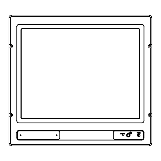
Due to product enhancement in Q4 2008, the MMC series went through a Product Change Notification where the HDD LED and Reset Button Aperture was removed from standard factory models. Instead, these features was provided as an option. Reference: http://www.hatteland-display.com/mails/30_2008_pcn.html or review the appropriate user manual: http://www.hatteland-display.com/pdf/manual/ inb100014-1_usermanual_mmc_etx_slim_rev23.pdf... -
Page 23: Specifications
Specifications INB100014-1 (Rev 27) -
Page 24: Specifications - Jh 10T08 Mmc
3.5mm mini jack (depends on model) Power Supply Options: Mic In 3.5mm mini jack (depends on model) • 115 & 230VAC - 50/60Hz : Model JH 10T08 MMC A1 • 24 VDC : Model JH 10T08 MMC A2 Available Mechanical Options: Power Consumption: •... -
Page 25: Specifications - Jh 15T05 Mmc
Specifications - JH 15T05 MMC P R O D U C T S P E C I F I C A T I O N S - J H 1 5 T 0 5 M M C Note: All specifications are subject to change without prior notice! T E C H N I C A L D E S C R I P T I O N M E C H A N I C A L D E S C R I P T I O N TFT Technology:... -
Page 26: Specifications - Jh 19T02 Mmc
Specifications - JH 19T02 MMC PRODUCT SPECIFICATIONS - JH 19T02 MMC-xy Note: All specifications are subject to change without prior notice! T E C H N I C A L D E S C R I P T I O N M E C H A N I C A L D E S C R I P T I O N TFT Technology: Physical Considerations:... -
Page 27: Specifications - Jh 23T02 Mmc
Specifications - JH 23T02 MMC PRODUCT SPECIFICATIONS - JH 23T02 MMC Note: All specifications are subject to change without prior notice! T E C H N I C A L D E S C R I P T I O N M E C H A N I C A L D E S C R I P T I O N TFT Technology: Physical Dimensions:... - Page 28 This page left intentionally blank INB100014-1 (Rev 27)
-
Page 29: Technical Drawings
Technical Drawings INB100014-1 (Rev 27) -
Page 30: Technical Drawings - Jh 10T08 Mmc
Technical Drawings - JH 10T08 MMC Standard Version INB100014-1 (Rev 27) IND100132-94... -
Page 31: Technical Drawings - Jh 15T05 Mmc
Technical Drawings - JH 15T05 MMC Standard Version INB100014-1 (Rev 27) IND100132-62... -
Page 32: Bracket Version
Technical Drawings - JH 15T05 MMC Bracket Version INB100014-1 (Rev 27) IND100132-62... -
Page 33: Technical Drawings - Jh 19T02 Mmc
Technical Drawings - JH 19T02 MMC Standard Version INB100014-1 (Rev 27) IND100132-63... -
Page 34: Bracket Version
Technical Drawings - JH 19T02 MMC Bracket Version INB100014-1 (Rev 27) IND100132-63... -
Page 35: Technical Drawings - Jh 23T02 Mmc
Technical Drawings - JH 23T02 MMC Standard Version INB100014-1 (Rev 27) IND100132-68... -
Page 36: Bracket Version
Technical Drawings - JH 23T02 MMC Bracket Version INB100014-1 (Rev 27) IND100132-68... -
Page 37: Technical Drawings - Accessories
Technical Drawings - Accessories INB100014-1 (Rev 27) -
Page 38: Mmc Bracket Assembly
Technical Drawings - Accessories MMC Bracket Assembly INB100014-1 (Rev 27) IND100132-78... -
Page 39: 19 Inch Bracket
Technical Drawings - Accessories 19 Inch Bracket INB100014-1 (Rev 27) IND100132-78... -
Page 40: 10" Sun Visor
Technical Drawings - Accessories 10” Sun Visor INB100014-1 (Rev 27) IND100132-47... -
Page 41: 15" Sun Visor
Technical Drawings - Accessories 15” Sun Visor INB100014-1 (Rev 27) IND100132-109... -
Page 42: 19" Sun Visor
Technical Drawings - Accessories 19” Sun Visor INB100014-1 (Rev 27) IND100132-67... -
Page 43: 23" Sun Visor
Technical Drawings - Accessories 23” Sun Visor INB100014-1 (Rev 27) IND100132-112... -
Page 44: 15" Tft To 19" Rack Adapter
Technical Drawings - Accessories 15” TFT to 19” RACK Adapter INB100014-1 (Rev 27) IND100132-43... -
Page 45: 15" Tft To 17" Crt Adapter
Technical Drawings - Accessories 15” TFT to 17” CRT Adapter INB100014-1 (Rev 27) IND100132-137... -
Page 46: 19" Tft To 21" Crt Adapter
Technical Drawings - Accessories 19” TFT to 21” CRT Adapter INB100014-1 (Rev 27) IND100132-44... -
Page 47: Appendixes
Appendixes INB100014-1 (Rev 27) -
Page 48: Pin Assignments - Common Connectors
Pin Assignments - Common Connectors Note: Not all connectors may be available on your specific product. This depends on the amount of additional hardware installed from factory, or customized solutions. These pin assignments are for the common connectors used. Connectors are seen from users Point Of View (POV). Pin Assignments - USB TYPE A Pin Assignments - RJ45 10/100 LAN Pin 2: Negative Data... - Page 49 Pin Assignments - Common Connectors Pin Assignments - 25P Parallel 13 12 11 10 9 8 7 6 5 4 3 2 1 25 24 23 22 21 20 19 18 17 16 15 14 Pin 01 - STROBE This signal indicates to the printer that data at PD7..0 are valid. Pin 02 - DATA0 Parallel data bus from PC board to printer.
- Page 50 Pin Assignments - Common Connectors (Additional) Pin Assignments - 9P Serial COM RS422 Pin Assignments - 9P Serial COM RS485 4 3 2 1 4 3 2 1 9 8 7 6 9 8 7 6 Pin 01 - N/C Not Connected Pin 01 - N/C Not Connected...
-
Page 51: Basic Trouble-Shooting
Basic Trouble-shooting GENERAL ISSUES FOR TFT PANEL BASED PRODUCTS Note: Applies for a range of various products. This is only meant as a general guide. O PICTURE / LED BEHAVIOUR: If there is no light at all in the LED at the FRONT, check power cables. If the LED in front is green then check if the brightness knob is turned to the right (max brightness). -
Page 52: Declaration Of Conformity
Declaration of Conformity We, manufacturer Hatteland Display AS Åmsosen, N-5578 Nedre Vats, Norway declare under our sole responsibility that the JH MMD, JH MMC, JH STD, JH MIL, HM NMD HM MIL, HM CMD, HT STD, HD MMD & HT MMC product ranges is in conformity with the following standards in accordance with the EMC Directive. -
Page 53: Return Of Goods Information
Return of goods: (Applies not to warranty/normal service/repair of products) Hatteland Display referenced as “manufacturer” in this document. Before returning goods, please contact your system supplier before sending anything directly to manufacturer. When you return products after loan, test, evaulation or products subject for credit, you must ensure that all accessories received from our warehouse is returned. -
Page 54: Terms
Goods are considered delivered to customer when handed over to charterer. 8) FREIGHT / PACKING / FORWARDING FEE Hatteland Display AS charge NOK 50,- in forwarding fee for orders below NOK 1000,-. Freight charge according to expenses for orders above NOK 1000,-. VAT not included. - Page 55 Terms 12) CANCELLATION / RETURN Binding sales contract is concluded when we have confirmed customer’s purchase order. Any disagreements in our order confirmation must be reported to seller within 6 days. The agreement can not be altered without our permission, after acceptance from our supplier.
-
Page 56: Pixel Defect Policy
TFT display. Neither the production at LCD-supplier nor the use of a LCD-Monitor after shipment can be influenced by Hatteland Display. Hence Hatteland Display cannot be made responsible for such dot failures. -
Page 57: Notes
The separate and full documentation for third party components (including options that are factory installed) are available on attached CD. The printed physical manual only covers specific information for Hatteland products, and not generally includes third party components. Appendix INB100014-1 (Rev 27) -
Page 58: Important Bios Reset / No Picture Information
Notes Important BIOS Reset / No picture information Please note that when performing a “Load Optimized Defaults” or “Load Fail-Safe Defaults” command in the BIOS menu, or if the internal ETX processor module was replaced, the picture on the TFT display will be black and the sync will be lost upon restart. No picture will be present on the MMC unit! However, by using the standard RGB OUT DSUB connector connected to an external TFT Display or CRT Monitor, you will get a cloned picture from the MMC unit. -
Page 59: Revision History
Available processor now up to 1.8GHz and removal of HDD LED and Reset Button Aperture. Revised Physical Overview Chapter 17 Dec 2008 Updated testing and type approvals for various products. Revised drawings for JH 10T08 MMC regarding power mounting bracket. 26 Mar 2009 Revised specifications Added info about Serial Remote Control Interface (SCOM) Fixed corrupted layout in the Connections chapter.
Need help?
Do you have a question about the JH 10T08 MMC and is the answer not in the manual?
Questions and answers