Table of Contents
Advertisement
Quick Links
U S E R M A N U A L
Compact Fanless Computers
HT B17 xxy-zzzz
HT B18 xxy-zzzz
xx=standard or customized
y=operating system
zzzz=configuration dependent
Please visit www.hatteland-display.com for the latest electronic version of this manual.
Hatteland Display AS, Åmsosen, N-5578 Nedre Vats, Norway
Tel: (+47) 4814 2200 - mail@hatteland-display.com - www.hatteland-display.com
User Manual HT B17 / HT B18
Updated: 13 Aug 2013
Doc Id: INB100032-5 (Rev 14)
Created: 363
Approved: 6987
Advertisement
Table of Contents

Related Manuals for Hatteland HT B17 Series


Summary of Contents for Hatteland HT B17 Series
- Page 1 Updated: 13 Aug 2013 Doc Id: INB100032-5 (Rev 14) Created: 363 Approved: 6987 Please visit www.hatteland-display.com for the latest electronic version of this manual. Hatteland Display AS, Åmsosen, N-5578 Nedre Vats, Norway Tel: (+47) 4814 2200 - mail@hatteland-display.com - www.hatteland-display.com...
- Page 2 Copyright © 2013 Hatteland Display AS Aamsosen, N-5578 Nedre Vats, Norway. All rights are reserved by Hatteland Display AS. This information may not, in whole or in part, be copied, photocopied, reproduced, translated or reduced to any electronic medium or machine- readable form without the prior written consent of Hatteland Display AS.
-
Page 3: Table Of Contents
Contents Contents ..................3 Contents of package ................5 General ..................7 About this manual ................8 About Hatteland Display ..............8 www.hatteland-display.com ..............8 Contact Information ................8 Computers introduction ..............9 Basic Construction - HT B17 ............10 Basic Construction - HT B18 ............11 Product Labels (Examples) .............. - Page 4 Contents Technical Drawings ..............31 Technical Drawings - HT B17 ............32 Technical Drawings - HT B18 ............33 - HWCode00 ................33 - HWCode90 ................34 Technical Drawings - Accessories ........35 Technical Drawings - Mounting Bracket Kit ........36 for HT B17 and HT B18 ..............36 Technical Drawings - Mounting Plate/Cable Tension Relievers ..
-
Page 5: Contents Of Package
L17DPPK09JSU (cover) Documentation and Driver DVD for factory installed components like mainboard, IDE, network etc. For most recent drivers, please visit “www.hatteland-display.com/archive”. Menu browser for Note: To use this DVD disc you will need an external USB CD/DVD drive or provide means of Microsoft®... - Page 6 This page left intentionally blank...
-
Page 7: General
General... -
Page 8: About This Manual
About Hatteland Display Hatteland Display is the leading technology provider of specialized display and computer products, delivering high quality, unique and customized solutions to the international maritime, naval and industrial markets. -
Page 9: Computers Introduction
2U, 3U and 4U. We continually develop our computers portfolio to make the best use of emerging computer technology so you can be sure that your Hatteland Display computer offers the power needed to run modern applications, with the flexibility to be installed wherever you want, for any marine use. -
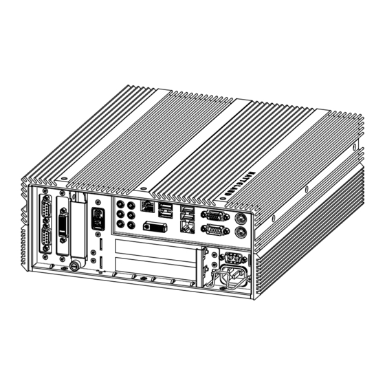
Page 10: Basic Construction - Ht B17
Basic Construction - HT B17 Basic Construction Compact Fanless Computer Chassis with cooling design Power Module Front plate with Serial Number Label Chassis Support Mechanics Connector plates Heat Pipe Cooling Mainboard I/O Connectors and CPU SSD/HDD and Casing Bottom chassis plate Standard model, customized versions may vary General... -
Page 11: Basic Construction - Ht B18
Basic Construction - HT B18 Basic Construction Compact Fanless Computer Chassis with cooling design Power Module Front plate with Serial Number Label Replaceable SSD/HDD and casing Connector plates Chassis Support Mechanics I/O Connectors Heat Pipe Cooling Mainboard and CPU Memory PCI Card &... -
Page 12: Product Labels (Examples)
Product Labels (Examples) Product Labels (Examples) Serial Number Label Placement (external) HT B17 HT B18 Serial Number Label Layout Product Type Manufacturer & Country Input Voltages & Power Rating Manufactured Date yyyymmdd Barcode (TYP+SNO) Product Hardware Revision Label Size: 6cm x 2cm Serial Number Label Nomenclature XX XYY XXX-XYYY-YYYYYY NOMENCLATURE - X=Letters, Y=Numbers... -
Page 13: Installation
Installation... -
Page 14: Installation And Mounting Of Computers
The classification is only valid for approved mounting brackets provided by Hatteland Display. The unit shall be mounted stand-alone without any devices or loose parts placed at or nearby the unit. Any other type of mounting might require test and re-classification. -
Page 15: Cables
General Installation Recommendations Cables Use only high quality shielded signal cables. For RGB/DVI cables use only cables with separate coax for Red, Green and Blue. Configuring DC power input housing connector FIG 3 Note: Only applicable for certain models! FIG 1 For installations that require DC power input, use the provided 2-pin DC Power Input housing with internal cable screw terminal. -
Page 16: Accessible Ssd (Hard Drive Hdd) Removal / Replacement Ht B18
General Installation Recommendations Accessible SSD (Hard Drive HDD) removal / replacement HT B18 Note: Areas of interest are marked in this section with symbols in color. Please power off and disconnect ALL cables from the computer unit before proceeding! ▼ 1: Unscrew 1 pcs of knob screw anti-clockwise as ▼... -
Page 17: Internal Pci Cards / Brackets Dismounting And Mounting Ht B18
General Installation Recommendations Internal PCI Cards / Brackets dismounting and mounting HT B18 Note: Areas of interest are marked in this section with symbols in color. Please power off and disconnect ALL cables from the computer unit before proceeding! ▼ 2: Unscrew 6 pcs countersunk screws and remove ▼... -
Page 18: Internal Ssd (Hard Drive Hdd) Removal / Replacement Ht B1X
General Installation Recommendations Internal SSD (Hard Drive HDD) removal / replacement HT B1x Note: Areas of interest are marked in this section with symbols in color. Please power off and disconnect ALL cables from the computer unit before proceeding! HT B17 used as illustration in this procedure, but it is valid for both HT B17 and HT B18 computers. -
Page 19: Physical Overview - Ht B17
Physical Overview - HT B17 Front area of computer 2.5” internal S-ATA SSD Hard Drive Reset Button, Power LED & Button Power LED & Button: To turn ON the computer, press down button and release it immediately. The Power LED indication riing will illuminate green and the operating system will automatically boot. - Page 20 Physical Overview - HT B17 Operation/Connection area of computer DC Power Input Network #2 DVI-D OUT (D2) USB 1,2,3,4 RGB/VGA OUT Keyboard Port HDD LED Mouse Port AC Power Input DVI-D OUT (D1) Audio IN/OUT Connectors Network #1 COM1 RS-232 COM1 Serial Port INPUT/OUTPUT: Supports RS-232 using D-SUB 9P Male connectors.
- Page 21 Physical Overview - HT B17 Audio INPUT/OUTPUT: All connectors are 3.5” Jack Stereo. AC’97 audio support. 7.1 channel. HD Audio. It can be configured via the operating system to act as 2-channel, 4-channel, 6-channel or 8-channel. Please review 3rd party driver software/ manual to configure the channel setup.
- Page 22 Physical Overview - HT B17 DC POWER INPUT: Connect your DC power cable to the 2P Amphenol FCC17 D-SUB Connector (male). Secure the cable to the hex spacers provided on the unit, and secure the other end to your power supply. The internal DC power module supports 24VDC and is part of the Multipower functionality for the unit.
-
Page 23: Physical Overview - Ht B18
Physical Overview - HT B18 Operation/Connection area of computer Reset Button, Power LED & Button Network #2 USB 1,2,3,4 RGB/VGA OUT Replaceable 2.5 SSD COM1 RS-232 Network #1 DVI-D OUT (D2) Hard Drive Keyboard Port Mouse Port COM2 RS-232 RS-422 HDD LED RS-485 DC Power Input... - Page 24 Physical Overview - HT B18 2.5” Replaceable internal S-ATA SSD Hard Drive: The B18 unit can use 1 x SSD, 2.5” as the main data storage device. The operating system and all other files will be placed on this, normally visible as drive C: This device is normally factory installed option. The storage device can be easily be upgraded or replaced by loosing the fasten screw and pull the slot out.
- Page 25 Physical Overview - HT B18 USB1,2,3,4 INPUT/OUTPUT: Supports any USB1.1 (12Mbps) or USB2.0 (480Mbps) compliant peripherals. Drivers for most USB devices are usually included in operating system or on separate installation CD’s delivered with Third Party products. USB 1.1 devices will operate in USB 1.1 mode (12 Mbps). PS/2 Mouse and PS/2 Keyboard INPUTS: Connect the PS/2 mouse cable to the PS/2 5P Connector (female) marked with MS.
- Page 26 This page left intentionally blank...
-
Page 27: Specifications
Specifications... -
Page 28: Specifications - Ht B17
= Microsoft® Windows® Embedded Enterprise (Win Server 2008 Eng, 32bit) For a full overview of typenumbers, please review the following link: www.hatteland-display.com/pdflink/ind100780-5.php M E C H A N I C A L D E S C R I P T I O N... -
Page 29: Specifications - Ht B18
= Microsoft® Windows® Embedded Enterprise (Win Server 2008 Eng, 32bit) For a full overview of typenumbers, please review the following link: www.hatteland-display.com/pdflink/ind100780-5.php M E C H A N I C A L D E S C R I P T I O N... - Page 30 This page left intentionally blank...
-
Page 31: Technical Drawings
Technical Drawings... -
Page 32: Technical Drawings - Ht B17
Technical Drawings - HT B17 IND100132-185... -
Page 33: Technical Drawings - Ht B18
Technical Drawings - HT B18 - HWCode00 IND100132-182... -
Page 34: Hwcode90
Technical Drawings - HT B18 - HWCode90 IND100132-182... -
Page 35: Technical Drawings - Accessories
Technical Drawings - Accessories... -
Page 36: Technical Drawings - Mounting Bracket Kit
Technical Drawings - Mounting Bracket Kit for HT B17 and HT B18 IND100132-192... -
Page 37: Technical Drawings - Mounting Plate/Cable Tension Relievers
Technical Drawings - Mounting Plate/Cable Tension Relievers for HT B17 IND100132-192... -
Page 38: For Ht B18 Hwcode00
Technical Drawings - Mounting Plate/Cable Tension Relievers for HT B18 HWcode00 IND100132-192... -
Page 39: For Ht B18 Hwcode90
Technical Drawings - Mounting Plate/Cable Tension Relievers for HT B18 HWcode90 IND100132-192... -
Page 40: Technical Drawings - Mounting Plate/Cable Tension Relievers
Technical Drawings - Mounting Plate/Cable Tension Relievers for HT B17, B18, B07, B08 IND100132-183... -
Page 41: Technical Drawings - Mounting Plate
Technical Drawings - Mounting Plate for HT B17, B18, B07, B08 IND100132-183... - Page 42 This page left intentionally blank...
-
Page 43: Appendixes
Appendixes... -
Page 44: Ssd Selection Guide
- Selection / dimensioning of SSD device shall be done towards data rate , size of footprint is secondary and in most cases not the dimensioning factor. Hatteland Displays Recommendations, MLC device Use of OS image adapted for HDD without any modifications for SSD: >... - Page 45 SSD Selection Guide Calculation of required size of SSD (Multi-Level Cell - MLC) device) The table below details the write endurance of the Intel® SSD 320 Series in an enterprise environment. Write endurance is measured while running 100% random 4KB (4096 bytes) writes spanning 100% of the drive using Iometer.
- Page 46 SSD Selection Guide Example A general assessment based on requirements to determine the most suitable SSD device. When these factors are known or specified in detail, we can calculate and conclude which SSD device is most suitable (see bottom of page). Question Client Answer We need to know how much data is written to disk...
- Page 47 SSD Selection Guide Preparation 1: Install "Intel® Solid-Sate Drive Toolbox" at target system. 2: Install the unit in valid configuration, i.e. the application shall running valid use case, if possible use worst case scenario (with respect to disk activity). 3: Before start of measurement, check and store actual SMART data. - Start "Intel®...
-
Page 48: Pinout Assignments - Common Connectors
Note: The table above lists commonly-used RS-232 signals and pin Pin 1: Video Signal Ground Shield assignments, however Serial Communication for Hatteland Display products may vary from product to product to support different end user systems. Please check additional pin assignments section in this manual for specific RS-232/RS-422/RS-485 pin assignments for your exact product. - Page 49 Pinout Assignments - Common Connectors Pin Assignments - 25P Parallel 13 12 11 10 9 8 7 6 5 4 3 2 1 25 24 23 22 21 20 19 18 17 16 15 14 Pin 01 - STROBE This signal indicates to the printer that data at PD7..0 are valid. Pin 02 - DATA0 Parallel data bus from PC board to printer.
- Page 50 Pin Assignments - Common Connectors (Additional) Pin Assignments - 9P Serial COM RS422 Pin Assignments - 9P Serial COM RS485 4 3 2 1 4 3 2 1 9 8 7 6 9 8 7 6 Pin 01 - N/C Not Connected Pin 01 - N/C Not Connected...
-
Page 51: Trouble-Shooting
HT 216, HT 416, HT B17, HT B18, HT B21, HT B22 and HT/HM C01 (Win7 only) computer models. The recovery image fi le is not accessible from any operating system, only by the Recovery Kit (USB Flash) provided by Hatteland Display. -
Page 52: Declaration Of Conformity
Declaration of Conformity We, manufacturer, Hatteland Display AS, Åmsosen, N-5578 Nedre Vats, Norway declare under our sole responsibility that the JH MMD, JH MMC, JH STD, JH MIL, HM NMD, HM MIL, HM CMD, HT STD, HD MMD, HM MMD, HT MMC, HD MMC and HT (computers) product ranges is in conformity with the following standards in accordance with the EMC Directive. -
Page 53: Return Of Goods Information
Return of goods: (Applies not to warranty/normal service/repair of products) Hatteland Display referenced as “manufacturer” in this document. Before returning goods, please contact your system supplier before sending anything directly to manufacturer. When you return products after loan, test, evaulation or products subject for credit, you must ensure that all accessories received from our warehouse is returned. -
Page 54: Terms
Goods are considered delivered to customer when handed over to charterer. 8) FREIGHT / PACKING / FORWARDING FEE Hatteland Display charge NOK 50,- in forwarding fee for orders below NOK 1000,-. Freight charge according to expenses for orders above NOK 1000,-. VAT not included. - Page 55 Terms 12) CANCELLATION / RETURN Binding sales contract is concluded when we have confirmed customer’s purchase order. Any disagreements in our order confirmation must be reported to seller within 6 days. The agreement can not be altered without our permission, after acceptance from our supplier.
-
Page 56: Notes
Notes General Notes: - License Terms for the installed OEM Operating System (OS) can be found on root of main boot device, (typically “C:\” partition). - For certain computers, the on-board signal output (RGB, VGA, DVI) will be disabled if additional graphics card is installed and present in one of the PCI/PCIe slots. - Page 57 User Notes Appendix IND100077-24...
-
Page 58: Revision History
Revision History Rev. Date Notes 00_1 29 Oct 2009 Internal review release. 05 Nov 2009 First official release. 08 Jan 2010 Revised contents of package, added HT 00237 and info about 3rd party hardware (page 4) Added text about ground (GND) in installation chapter (page 18,21). Added HT B17 specifications, drawings and illustrations (page 10,15,16,17,18,24,28) 28 Jan 2010 Added Basic Construction illustration HT B18 (page 11) - Page 59 IND100077-100...
- Page 60 w ww .hat tel and-di s p l ay . com...
Need help?
Do you have a question about the HT B17 Series and is the answer not in the manual?
Questions and answers