Table of Contents
Advertisement
Quick Links
U S E R M A N U A L
Series 1 - Maritime Multi Computer Models
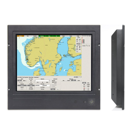
JH 15T17 MMC-xxx-Axxx - 15.0 inch Maritime Multi Computer
JH 19T14 MMC-xxx-Axxx - 19.0 inch Maritime Multi Computer
Tel: (+47) 4814 2200 - mail@hatteland-display.com - www.hatteland-display.com
Released
Please visit www.hatteland-display.com for the latest electronic version of this manual.
Hatteland Display AS, Åmsosen, N-5578 Nedre Vats, Norway
User Manual MMC Series 1
Updated: 01 Apr 2011
Doc Id: INB100216-1 (Rev 8)
Created: 363
Approved: 6405
Advertisement
Table of Contents

Related Manuals for Hatteland 1 Series


Summary of Contents for Hatteland 1 Series
- Page 1 Updated: 01 Apr 2011 Doc Id: INB100216-1 (Rev 8) Created: 363 Approved: 6405 Please visit www.hatteland-display.com for the latest electronic version of this manual. Hatteland Display AS, Åmsosen, N-5578 Nedre Vats, Norway Tel: (+47) 4814 2200 - mail@hatteland-display.com - www.hatteland-display.com...
- Page 2 Information in this manual is copyrighted to the respective owners. All rights are reserved by Hatteland Display AS. This information may not, in whole or in part, be copied, photocopied, reproduced, translated or reduced to any electronic medium or machine-readable form without the prior written consent of Hatteland Display AS.
-
Page 3: Table Of Contents
Released Contents Contents ..................3 Contents of package ..................5 General .................... 7 About this manual ..................8 About Hatteland Display ................8 hatteland-display.com ................8 Contact Information ..................8 Maritime Multi Computer (MMC) - Introduction ..........9 Basic Construction ...................10 Touch screen products ................11 Touch screen Technology & Label markings ........12 Product Labeling (examples) ..............13... - Page 4 Released Contents Technical Drawings ..............31 Technical Drawings - JH 15T17 MMC-xxx-Axxx ........32 Standard Version ................32 Technical Drawings - JH 19T14 MMC-xxx-Axxx ........33 Standard Version ................33 Technical Drawings - Accessories ..........35 15” Sun Visor ...................36 19” Sun Visor ...................37 15”...
-
Page 5: Contents Of Package
Released Contents of package Item Description Illustration 1 pcs of power cable European Type F “Schuko” to IEC. EUR TYPE F Length 1.8m Note: Included in package for models with AC input. FS-CABLE EU 1 pcs of power cable US Type B plug to IEC. US TYPE B Length 1.8m Note: Included in package for models with AC input. - Page 6 Released This page left intentionally blank INB100216-1 (Rev 8)
-
Page 7: General
Released General INB100216-1 (Rev 8) -
Page 8: About This Manual
About Hatteland Display Hatteland Display is the leading technology provider of specialized display and computer products, delivering high quality, unique and customized solutions to the international maritime, naval and industrial markets. -
Page 9: Maritime Multi Computer (Mmc) - Introduction
ECDIS software through to engine monitoring and automation applications. It has power to spare too, so software developers can be sure that Hatteland Display Series 1 panel computers can handle the latest applications being designed for bridge and engine room systems in addition to other, more custom uses. -
Page 10: Basic Construction
Released Basic Construction Basic Construction - Series 1 Touch Screen (option) Sun Visor (option) Centerbox Water Cover (option) Mounting Bracket (option) Mechanics Glass Casing Front Frame Bonding Electronics / PCB’s Rotary Bracket (option) User Controls Logo label (option) Example with mounting bracket Example with sun visor, mounting bracket and rotary bracket General INB100216-1 (Rev 8) -
Page 11: Touch Screen Products
Introduction to products with touch screen Both Resistive and Capacitive touch screen solutions are used for our products. Please review specifications found in this manual or our website (www.hatteland-display.com) to find your exact type number and then determine if it uses Resistive or Capacitive. -
Page 12: Touch Screen Technology & Label Markings
All products are shipped with a Documentation and Drivers DVD or CD which contains suitable drivers for touch screens. You can also visit our website www.hatteland-display.com to view the same list (or even recently new added products) for our models with touch screen. -
Page 13: Product Labeling (Examples)
J H 1 9 T 1 M M C In this document we shall explain the typenumber structure for standard HATTELAND® Series 1 product ranges introduced in February 2008. Product Range ID Also shown is an example of a fi ctitious customer specifi ed product at the bottom. -
Page 14: Front Hatch Logo Label
Front Hatch Logo Label The Hatteland Display MMC front frame design offers an area for customized logo hatch label. This hatch/label can be ordered and customized with your own logo delivered from us. The hatch is IP66 rated to protect the front mounted connector(s) behind the hatch. -
Page 15: Installation
Released Installation INB100216-1 (Rev 8) -
Page 16: Installation And Mounting
Released General Installation Recommendations Installation and mounting 1. Most of our products are intended for various methods of installation or mounting (panel mounting, bracket mounting, ceiling/wall mounting etc.); for details, please see the relevant mechanical drawings. 2. Adequate ventilation is a necessary prerequisite for the life of the product. The air inlet and outlet openings must definitely be kept clear;... -
Page 17: Ergonomics
Released General Installation Recommendations - When a product is being installed, the surface base or bulkhead must be checked to ensure that it is flat in order to avoid twisting of the unit when the fixing screws are tightened, because such twisting would impair mechanical functions. -
Page 18: Cables
Released General Installation Recommendations Cables Use only high quality shielded signal cables. Cable Entries & Connectors (Marked area) - Illustration only Bottom View Back View Maximum Cable Length Any cable should generally be kept as short as possible to provide a high quality input/output. The maximum signal cable length will depend on the signal resolution and frequency, but also on the quality of the signal output from the computer/radar. -
Page 19: Rotary Bracket / Mounting Bracket Assembly Or Disassembly
Released General Installation Recommendations Rotary Bracket / Mounting Bracket Assembly or Disassembly Use the provided bolts included in the package to assemble the brackets. Follow the steps below. You must provide your own bolts to secure it to a table / desktop. Recommended size is: M10 and minimum 30mm in length. 3 pcs 4 pcs 4 pcs... -
Page 20: Physical Connections - Mmc / Xxc Based Units
Released Physical Connections - MMC / xxC based units Connection area of unit (illustration) + internal miniPCI slot Parallel (LPT) PS/2 Mouse PS/2 Keyboard USB 2,3,4,5 COM1, COM2 2 x GigaBit LAN DVI-I/RGB OUT Compact Flash Reader Power Input AC or DC Cable Tension To reduce tension of the cables you connect, secure them with a cable tie to the base... - Page 21 Released Physical Connections - MMC / xxC based units DVI-I OUT: DVI/RGB OUT enables a direct clone signal output from the computer. You may choose to use a DVI-I 29P cable directly or use a DVI-I -> RGB adapter to use a RGB/VGA HD D-SUB 15P instead for this purpose. Connect the cable to the Connector (female) and secure it to the hex spacers provided on the unit.
- Page 22 Released This page left intentionally blank INB100216-1 (Rev 8)
-
Page 23: Operation
Released Operation MMC Products INB100216-1 (Rev 8) -
Page 24: User Controls
Released User Controls USER CONTROLS OVERVIEW The units are available as two different factory user control configurations illustrated below. Buzzer Potmeter Keypad w/Status LED ring #1: Potmeter, Buzzer and Keypad Control with its Status LED Ring. Brightness for the unit is adjusted by turning the potmeter clockwise or anti-clockwise. - Page 25 Released User Controls KEYPAD FUNCTIONALITIES (unit model dependable) Not in use Power button Left button Right button Push Buttons Status LED Ring Not in use MENU/POWER ICON function as: Power On/Off. Note: MENU OSD is not available on MMC units. LEFT (◄) function as: Decrease Brightness.
-
Page 26: Status Led Overview
Released Status LED Overview Status LED Overview The unit features a multi purpose indicator LED status ring which through different patterns and realtime activity gives back the status of the signal detected, power on/off, calibration, menu activity and more. The LEDs are multicolored which either illuminate green or red, based on the activity. OFF (No power connected) OFF (Standby, power detected) ON (Signal Search) -
Page 27: Specifications
Released Specifications INB100216-1 (Rev 8) -
Page 28: Specifications - Jh 15T17 Mmc-Xxx-Axxx
*Note that all 15 inch with resistive touch screens can not be combined with bonding. Capabilities / Prepared for: • 1 x miniPCI (Require mod cation of terminal plate) For a full overview of typenumbers, please review the following link: www.hatteland-display.com/pdf/misc/ind100780-2_series1redesign_mmc_typenumber_desc.pdf Compass Safe Distance: JH 15T17 MMC-Axx-Axxx Standard: 55cm Steering: 35cm... -
Page 29: Specifications - Jh 19T14 Mmc-Xxx-Axxx
*Note that 19 inch with resistive touch screen can not be combined with bonding. Capabilities / Prepared for: • 1 x miniPCI (Require mod cation of terminal plate) For a full overview of typenumbers, please review the following link: www.hatteland-display.com/pdf/misc/ind100780-2_series1redesign_mmc_typenumber_desc.pdf Compass Safe Distance: JH 19T14 MMC-Axx-Axxx Standard: 75cm Steering: 45cm... - Page 30 Released This page left intentionally blank INB100216-1 (Rev 8)
-
Page 31: Technical Drawings
Released Technical Drawings INB100216-1 (Rev 8) -
Page 32: Technical Drawings - Jh 15T17 Mmc-Xxx-Axxx
Released Technical Drawings - JH 15T17 MMC-xxx-Axxx Standard Version INB100216-1 (Rev 8) IND100132-172... -
Page 33: Technical Drawings - Jh 19T14 Mmc-Xxx-Axxx
Released Technical Drawings - JH 19T14 MMC-xxx-Axxx Standard Version INB100216-1 (Rev 8) IND100132-173... - Page 34 Released This page left intentionally blank INB100216-1 (Rev 8)
-
Page 35: Technical Drawings - Accessories
Released Technical Drawings - Accessories INB100216-1 (Rev 8) -
Page 36: 15" Sun Visor
Released Technical Drawings - Accessories 15” Sun Visor INB100216-1 (Rev 8) IND100132-109... -
Page 37: 19" Sun Visor
Released Technical Drawings - Accessories 19” Sun Visor INB100216-1 (Rev 8) IND100132-67... -
Page 38: 15" Rotary Bracket
Released Technical Drawings - Accessories 15” Rotary Bracket INB100216-1 (Rev 8) IND100132-148... -
Page 39: 17",19", 20", 23" Rotary Bracket
Released Technical Drawings - Accessories 17”,19”, 20”, 23” Rotary Bracket INB100216-1 (Rev 8) IND100132-46... -
Page 40: 15" Bracket
Released Technical Drawings - Accessories 15” Bracket INB100216-1 (Rev 8) IND100132-167... -
Page 41: 19" En60945 Bracket
Released Technical Drawings - Accessories 19” EN60945 Bracket INB100216-1 (Rev 8) IND100132-69... -
Page 42: 15" Tft To 19" Rack Adapter
Released Technical Drawings - Accessories 15” TFT to 19” RACK Adapter INB100216-1 (Rev 8) IND100132-43... -
Page 43: 15" Tft To 17" Crt Adapter
Released Technical Drawings - Accessories 15” TFT to 17” CRT Adapter INB100216-1 (Rev 8) IND100132-137... -
Page 44: 19" Tft To 21" Crt Adapter
Released Technical Drawings - Accessories 19” TFT to 21” CRT Adapter INB100216-1 (Rev 8) IND100132-44... -
Page 45: 19" Tft To 21" Crt Adapter Custom
Released Technical Drawings - Accessories INB100216-1 (Rev 8) 19” TFT to 21” CRT Adapter Custom IND100132-187... -
Page 46: Vesa Bracket - 15
Released Technical Drawings - Accessories VESA Bracket - 15” INB100216-1 (Rev 8) IND100132-113... -
Page 47: Vesa Bracket - 19
Released Technical Drawings - Accessories VESA Bracket - 19” INB100216-1 (Rev 8) IND100132-45... -
Page 48: Water Cover - 15
Released Technical Drawings - Accessories Water Cover - 15” INB100216-1 (Rev 8) IND100132-117... -
Page 49: Water Cover - 19" (Hw01)
Released Technical Drawings - Accessories Water Cover - 19” (HW01) INB100216-1 (Rev 8) IND100132-136... - Page 50 Released This page left intentionally blank INB100216-1 (Rev 8)
-
Page 51: Appendixes
Released Appendixes INB100216-1 (Rev 8) -
Page 52: Pin Assignments - Common Connectors
Note: The table above lists commonly-used RS-232 signals and pin Pin 1: Video Signal Ground Shield assignments, however Serial Communication for Hatteland Display products may vary from product to product to support different end user systems. Please check additional pin assignments section in this manual for specific RS-232/RS-422/RS-485 pin assignments for your exact product. - Page 53 Released Pin Assignments - Common Connectors Pin Assignments - 25P Parallel 13 12 11 10 9 8 7 6 5 4 3 2 1 25 24 23 22 21 20 19 18 17 16 15 14 Pin 01 - STROBE This signal indicates to the printer that data at PD7..0 are valid.
- Page 54 Released Pin Assignments - Common Connectors (Additional) Pin Assignments - 9P Serial COM RS-485/RS-422 Pin Assignments - 9P Serial COM RS-485/RS-422 Full Duplex Mode Half Duplex Mode 4 3 2 1 4 3 2 1 9 8 7 6 9 8 7 6 Pin 01 - N/C Not Connected Pin 01 - N/C...
-
Page 55: Basic Trouble-Shooting
Released Basic Trouble-shooting GENERAL ISSUES FOR TFT PANEL BASED PRODUCTS Note: Applies for a range of various products. This is only suitable for general guidance. O PICTURE / LED BEHAVIOUR: If there is no light at all in the LED at the FRONT, check power cables. If the LED in front is green then check if the brightness knob is turned to the right (max brightness). -
Page 56: Declaration Of Conformity
Released Declaration of Conformity We, manufacturer Hatteland Display AS Åmsosen, N-5578 Nedre Vats, Norway declare under our sole responsibility that the JH MMD, JH MMC, JH STD, JH MIL, HM NMD, HM MIL, HM CMD, HT STD, HD MMD, HM MMD & HT MMC product ranges is in conformity with the following standards in accordance with the EMC Directive. -
Page 57: Return Of Goods Information
Return of goods: (Applies not to warranty/normal service/repair of products) Hatteland Display referenced as “manufacturer” in this document. Before returning goods, please contact your system supplier before sending anything directly to manufacturer. When you return products after loan, test, evaulation or products subject for credit, you must ensure that all accessories received from our warehouse is returned. -
Page 58: Terms
Goods are considered delivered to customer when handed over to charterer. 8) FREIGHT / PACKING / FORWARDING FEE Hatteland Display AS charge NOK 50,- in forwarding fee for orders below NOK 1000,-. Freight charge according to expenses for orders above NOK 1000,-. VAT not included. - Page 59 Released Terms 12) CANCELLATION / RETURN Binding sales contract is concluded when we have confirmed customer’s purchase order. Any disagreements in our order confirmation must be reported to seller within 6 days. The agreement can not be altered without our permission, after acceptance from our supplier.
-
Page 60: Pixel Defect Policy
TFT display. Neither the production at LCD-supplier nor the use of a LCD-Monitor after shipment can be influenced by Hatteland Display. Hence Hatteland Display cannot be made responsible for such dot failures. -
Page 61: Notes
Released Notes General Notes: (For all products) - The unit is type approved according to EN60945 4 th , 4.4, equipment category b) protected from the weather. - Other type approvals applies for the different products. Please see Testing & Approvals Overview section in this manual for more information. - Use of brightness and push buttons may inhibit visibility of information at night. -
Page 62: Revision History
Released Revision History Rev. Date Notes 20 Aug 2009 Release for internal review. 02 Oct 2009 Official release for internet. 05 Nov 2009 Removed text for Capacitive touch screen. Page 11. Removed LRS type approval (pending) from specifications, page 28, 29 Added note about 15 inch with resistive touch screen &... - Page 63 Released Revision History Appendix INB100216-1 (Rev 8) IND100077-95...
- Page 64 Released h attel and-d isp l ay . com...
Need help?
Do you have a question about the 1 Series and is the answer not in the manual?
Questions and answers