
Related Manuals for Sena PS110


Summary of Contents for Sena PS110
-
Page 1: User Guide
Universal Device Servers HelloDevice Pro Series User Guide Version 1.0.0 2005-07-08... - Page 2 This device is not approved for use as a life-support or medical system. Any changes or modifications made to this device without the explicit approval or consent of Sena Technologies will void Sena Technologies of any liability or responsibility of injury or loss caused by any malfunction.
-
Page 3: Revision History
Revision history Revision Date Name Description V0.1.0 2005-05-25 O.J. Jung Initial Draft Revision for firmware v1.0.0 release V1.0.0 2005-07-08 O.J. Jung... -
Page 4: Table Of Contents
1.3. Product Specification......................... 9 1.4. Terminologies and acronyms ....................10 2. Getting Started 2.1. Panel Layout ........................... 12 2.1.1. PS110 Panel Layout ....................... 12 2.1.2. PS410/810 Panel Layout ....................13 2.2. Connecting the Hardware......................14 2.2.1. Connecting to the network ....................14 2.2.2. - Page 5 4.2.2. Port Title ......................... 41 4.2.3. Host Mode Configuration ....................41 4.2.4. Remote host configuration ....................50 4.2.5. Cryptography configuration ..................... 51 4.2.6. Serial port parameters ....................55 4.2.7. Modem configuration ...................... 59 4.2.8. Port Logging ........................60 4.2.9. Port event handling configurations .................. 61 4.2.10.
- Page 6 A 1.4. Serial Wiring Diagram ......................86 A 1.4.1. RS232 Serial Wiring Diagram ..................86 A 1.4.2. RS422/485 Serial Wiring Diagram ................87 Appendix 2. Pro Series Configuration files A 2.1. port1.conf ..........................88 A 2.2. filter.conf..........................88 A 2.3. snmp.conf ..........................88 Appendix 3.
-
Page 7: Introduction
1. Introduction 1.1. Overview The HelloDevice Pro Series is a Universal terminal server (or device server) that makes your legacy serial devices manageable by industry-standard Ethernet network. Based on open network protocols such as TCP/IP and UDP, it gives you ultimate flexibility to your serial devices. With the rich broadband network connectivity protocols such as DHCP and Dynamic DNS, you could easily manage the legacy serial devices over broadband Internet by using DSL or cable modem connection. -
Page 8: Package Check List
1.2. Package Check List - PS110/410/810 external box - External 110V (or 230V) power supply(PS110/PS410) or power cord(PS810) - Serial cable kit - Quick Start Guide - CD-ROM, including the Serial/IP, HelloDevice Manager and manuals... -
Page 9: Product Specification
1.3. Product Specification PS410 PS810 PS110 Serial Interface 1-port 4-port 8-port Serial speeds 75bps to 230Kbps Flow Control: Hardware RTS/CTS, Software Xon/Xoff RJ45 connector Signals: RS232 Rx, Tx, RTS, CTS, DTR, DSR, DCD, GND RS422 Rx+, Rx-, Tx+, Tx- RS485 Data+, Data-... -
Page 10: Terminologies And Acronyms
1.4. Terminologies and acronyms This section will define commonly used terms in this manual. These terms are related to Internetworking, and defined in regards to their use with Pro Series. MAC address On a local area network or other network, the MAC (Media Access Control) address is the computer's unique hardware number. - Page 11 Table 1-1 Acronym Table Internet Service Provider Personal Computer Network Interface Card Media Access Control Local Area Network Unshielded Twisted Pair ADSL Asymmetric Digital Subscriber Line Address Resolution Protocol Internet Protocol ICMP Internet Control Message Protocol User Datagram Protocol Transmission Control Protocol DHCP Dynamic Host Configuration Protocol SMTP...
-
Page 12: Getting Started
Lower-left lamp indicates the 10/100Base Ethernet Link status. Right two lamps indicate Receive and Transmit of the serial port. There is a factory reset switch bottom panel of PS110 and user can use this switch to restore factory default configuration. -
Page 13: Ps410/810 Panel Layout
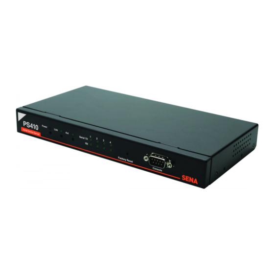
Figure 2-1 The panel layout of the PS110 2.1.2. PS410/810 Panel Layout The PS410/810 has three groups of LED indicator lamps to display the status, as shown in Figure 2-2 and Figure 2-3 (i.e. System, Ethernet and Serial ports). The first two lamps on the left side indicate Power, Ready(PS810 only). -
Page 14: Connecting The Hardware
4.2.6 and Appendix A for more detail information of serial communication type and its connection) Figure 2-2 The panel layout of the PS410 Figure 2-3 The panel layout of the PS810 2.2. Connecting the Hardware This section describes how to connect the Pro Series to the equipment for initial testing. - Connect the Pro Series to an Ethernet hub or switch - Connect the device - Connect a power source to the Pro Series... -
Page 15: Connecting To The Device
Figure 2-4 Connecting a network cable to the PS110 Figure 2-5 Connecting a network cable to the PS410 Figure 2-6 Connecting a network cable to the PS810 2.2.2. Connecting to the device Connect the console cable to the Pro Series serial port. To connect to the console port of the device, the user needs to consider the type of console port provided by the device itself. - Page 16 Note: If the configuration of the PS110 through the serial console is required, connect the serial cable to the serial port of user’s computer first. And push the Data/Console switch to the Console side. And also please set the position of DIP switch for serial mode to RS-232 mode. Configuration of the PS110 is discussed on Section 2.2.5.
-
Page 17: Connecting The Power
Connect the power cable to the Pro Series. If the power is properly supplied, the [Power] lamp will light up as red. Figure 2-10 Connecting the power to the PS110 Figure 2-11 Connecting the power to the PS410 Figure 2-12 Connecting the power to the PS810... -
Page 18: Accessing The System Console
Connect one end of the console cable to the console port on the Pro Series. (For PS110, Push the Data/Console switch to the Console side. And also please set the position of DIP switch for serial mode to RS-232 mode. Configuration of DIP switch is... - Page 19 Figure 2-14 Connecting a system console cable to the PS410 Figure 2-15 Connecting a system console cable to the PS810 Connect the other end of the cable to the serial port of the user’s computer. Run a terminal emulator program (i.e. HyperTerminal). Set up the serial configuration parameters of the terminal emulation program as follows: 9600 Baud rate Data bits 8...
- Page 20 settings are as follows. Login: root Password: root ProSeries login: root Password: After login, user can use various shell commands in the CLI(Command Line interface). For details on the CLI, refer to the chapter 7 CLI guide. “editconf” command will allow you to enter the text-menu driven interface and the menu screen in Figure 2-16 is displayed.
-
Page 21: Using Remote Console
2.2.6. Using Remote console The IP address of the Pro Series must be known before users can access the Pro Series using the Remote console (see chapter 3 Network Configuration for details). The default IP address of Pro Series is 192.168.161.5. The Remote console access function can be disabled in the remote host access option (3.5 IP Filtering for details). -
Page 22: Accessing The Web Browser Management Interface
2.3. Accessing the Web Browser Management Interface The Pro Series supports both HTTP and HTTPS (HTTP over SSL) protocols. The Pro Series also provides has its own Web management pages. To access the Pro Series Web management page, enter the IP address or resolvable hostname of the Pro Series into the web browser’s URL/Location field. - Page 23 Figure 2-19 The Pro Series web management screen...
-
Page 24: Network Configuration
3. Network Configuration 3.1. IP Configuration The Pro Series requires a valid IP address to operate within the user’s network environment. If the IP address is not readily available, contact the system administrator to obtain a valid IP address for the Pro Series. -
Page 25: Using A Static Ip Address
3.1.1. Using a Static IP Address When using a Static IP address, the user must manually specify all the configuration parameters associated with the IP address of the Pro Series. These include the IP address, the network subnet mask, the gateway computer and the domain name server computers. This section will look at each of these in more detail. -
Page 26: Using Dhcp
usually easier to remember. The DNS server is the host that can translate such text-based domain names into the numeric IP addresses for a TCP/IP connection. The IP address of the DNS server must be able to access the host site with the provided domain name. -
Page 27: Snmp Configurations
address each time it boots up. The IP address should be reserved on the DHCP server side to assure that the user always knows the newly assigned Pro Series address. In order to reserve the IP address in the DHCP network, the administrator needs the MAC address of the Pro Series found on the label sticker at the bottom of the Pro Series. -
Page 28: Mib-Ii System Objects Configuration
Figure 3-2 SNMP Configuration 3.2.1. MIB-II System objects Configuration MIB–II System objects configuration sets the System Contact, Name, Location, and Authentication- failure traps used by the SNMP agent of the Pro Series. These settings provide the values used for the MIB-II sysName, sysContact, sysLocation, sysService and enableAuthenTrap. -
Page 29: Access Control Configuration
EnablePoweronTraps: Indicates whether the SNMP agent process is permitted to generate power-on traps. EnableAuthenTrap: Indicates whether the SNMP agent process is permitted to generate authentication-failure traps. The value of this object overrides any configuration information; as such, it provides a means whereby all authentication-failure traps may be disabled.. EnableLoginTrap: Indicates whether the SNMP agent process is permitted to generate system login traps for console, telnet and Web access. -
Page 30: Dynamic Dns Configuration
Figure 3-3 Browsing MIB-II OIDs of Pro Series SNMP agent using SNMP Browser (AdventNet MibBrowser) 3.3. Dynamic DNS Configuration When users connect the Pro Series to a DSL line or use a DHCP configuration, the IP address might be changed whenever it reconnects to the network. It can therefore be very difficult to post all related contacts for each new IP address. -
Page 31: Smtp Configuration
up an account in their Members' NIC (Network Information Center - http://members.dyndns. org). The user may then add a new Dynamic DNS Host link after logging in to their Dynamic DNS Network Services Members NIC. After enabling the Dynamic DNS service in the Dynamic DNS Configuration menu, the user must enter the registered Domain Name, User Name, and Password. -
Page 32: Ip Filtering
SMTP servers often check only the sender’s host domain name of the email address for validity. Consequently, the email address set for the device can use an arbitrary username with a registered hostname (i.e. arbitrary_user@yahoo.com or anybody@sena.com). The SMTP user name and SMTP user password are required when either SMTP with authentication or POP-before-SMTP mode is selected. - Page 33 - Only one host of a specific IP address can access a specific service of the Pro Series - Hosts on a specific subnet can access a specific service of the Pro Series - Any host can access a specific service of the Pro Series The IP filtering feature for access to Telnet console, SSH console, Web server or each port may be enabled or disabled.
- Page 34 Figure 3-7 IP filtering Configuration The Pro Series also provide users with simple configuration way to block the specific services or serial ports from all hosts. If user set any service option as “Drop all”, then all access to the service from external will be blocked.
-
Page 35: Syslog Server Configuration
Table 3-2 Input examples of Option and IP address/mask combination Input format Allowable Hosts Option IP address/mask Any host 0.0.0.0/0.0.0.0 Normal 192.168.1.120 192.168.1.120/255.255.255.255 Normal Any host except 192.168.1.120/255.255.255.255 Invert 192.168.1.120 192.168.1.1 ~ 192.168.1.0/255.255.255.0 Normal 192.168.1.254 192.168.0.1 ~ 192.168.0.0/255.255.0.0 Normal 192.168.255.254 192.168.1.1 ~ 192.168.1.0/255.255.255.128 Normal... -
Page 36: Nfs Server Configuration
If the SYSLOG service is enabled and the SYSLOG server configuration is properly set up, the user may configure the storage location for the system log or port data log of the Pro Series as SYSLOG server. For more information about the configuration of port/system log storage location, please refer to section, 4.2.8 Port Logging and 5.2 System Logging. - Page 37 up situation, the Pro Series provides a TCP “keep-alive” feature. The Pro Series will send packets back and forth through the network periodically to confirm that the network is still alive. The corresponding TCP session is closed automatically if there’s no response from the remote host. To use the TCP “keep-alive”...
-
Page 38: Serial Port Configuration
4. Serial Port Configuration 4.1. Overview The serial port configuration capability allows the user to configure the host mode of each port, serial communication parameters, cryptography, port logging parameters and other related parameters. The serial port’s host mode can be set as any of the following: TCP : The Pro Series operates as a TCP server and client. - Page 39 Inactivity timeout (0 for unlimited) Accept unlisted Send unlisted Modem emulation Add or Edit a remote host Host IP address Host port Remote host Backup host IP address Backup host port Remove a remote host Cryptography SSLv3 Baud rate Data bits Parity Stop bits Flow control...
-
Page 40: Serial Port Configuration
Figure 4-1 Serial port configuration main screen 4.2. Serial Port Configuration Individual Port Configurations of the Pro Series are classified into eight(8) groups: 1. Port enable/disable 2. Port title 3. Host mode 4. Cryptography 5. Serial port parameters 6. Modem configuration 7. -
Page 41: Port Title
4.2.2. Port Title Users can enter descriptive information for each port based on the device attached to it. This can include the device type, vendor, and/or location. Figure 4-3 Port title configuration 4.2.3. Host Mode Configuration The Pro Series operating mode is called the “host mode.” Three host modes are available: TCP mode, UDP mode, Modem emulation mode. - Page 42 Figure 4-4 shows the main workspace screen for the host mode configuration. Figure 4-4 Host mode configuration 4.2.3.1. TCP mode For easier understanding of TCP modes, a simplified State Transition Diagram is often used. And to help users understand the diagram, the TCP state of the Pro Series is briefly described as follows. - [Listen] It represents “a waiting for a connection request from any registered remote host”.
- Page 43 If the Pro Series has sent a connection request to a remote host, the state is changed from [Closed] to [Sync-Sent]. This state is maintained until the remote host accepts the connection request. - [Established] It represents “an open connection”. If one of the hosts, the remote host or the Pro Series, accepts a connection request from the other, the connection is opened and state is changed into [Established].
- Page 44 The connected session will be disconnected when the remote host sends disconnection request or when no data transfer activity is found through the serial port for certain amount of time, which is “Inactivity timeout” (See Options in section 4.4 for details on Inactivity timeout). All the data remained in the serial port buffer will be cleared when it is disconnected.
- Page 45 information for remote host list configuration, please refer to 4.2.5 remote host list configuration section. Cyclic Connection If Cyclic Connection function is enabled, the Pro Series will make an attempt to connect to the user-defined remote host(s) at a given interval even if there’s no incoming serial data from the device connected to that serial port.
- Page 46 TCP connection request rejected Or internal TCP time-out Sync-Sent In-coming TCP Close request TCP connection request accepted Inactivity time-out Incoming data via serial port Data Established Incoming data Closed from remote host Accept Reject Listen Sync-Recvd Incoming TCP connection request Incoming data via serial port Figure 4-5 State Transition Diagram of TCP mode Inactivity Timeout...
- Page 47 configure cyclic connection, since UDP is a connectionless protocol. 1) Operations If a remote host sends a UDP datagram to the one of UDP Local port of the Pro Series, Pro Series first checks whether it is from one of the hosts configured on remote host configuration. If the remote host is one of the hosts configured on remote host configuration, then Pro Series transfers the data through the serial port.
- Page 48 Timeout, Pro Series will not send data from a serial port to the recent unlisted remote host again. Namely, Inactivity Timeout in UDP mode is the time maintained recent unlisted remote host list by Pro Series. NOTE: If user set Inactivity Timeout as 0 in UDP mode, Pro Series does not allow any new connection from/to remote host if the number of current remote host exceeds Max.
- Page 49 K3: RTS/CTS flow control (default) K4: Xon/Xoff (if supported) S, S0: DSR(PC) always high AT&Sn [CR][LF] S1: DSR(PC) shows TCP connection I, I0 : display “Sena Technologies, Inc.” ATIn [CR][LF] I3 : display model number <= Others : display “OK”...
-
Page 50: Remote Host Configuration
Table 4-3 AT commands Response Code Verbose Code Numeric Code Description (After “ATV1” command executed) (After “ATV0” command executed) Command executed CONNECT Modem connected to line RING A ring signal has been detected NO CARRIER Modem lost carrier signal ERROR Invalid command HelloDevice Serial... -
Page 51: Cryptography Configuration
Series to check status of primary remote host, so secondary remote host is meaningless. The maximum number of remote host is limited up to 8 in the Pro Series. Figure 4-7 shows Remote host configuration pages of the Web UI. (TCP mode) Figure 4-7 Remote host configuration 4.2.5. - Page 52 4-8 Cryptography configuration 4.2.5.1. Secure Sockets Layer(SSL) cryptography method By setting the cryptography method as SSL, the Pro Series can communicate with other device supporting SSLv3 cryptography method in encrypted sessions. SSL was developed by Netscape for use between clients and servers. SSL layers on top of any transport protocol and can run under application protocols such as HTTP.
- Page 53 1. The client sends the server the client's SSL version number, cipher settings, randomly generated data, and other information the server needs to communicate with the client using SSL. 2. The server sends the client the server's SSL version number, cipher settings, randomly generated data, and other information the client needs to communicate with the server over SSL.
- Page 54 Client Server Client Hello Server Hello Certificate ServerKeyExchange CertificateRequest Plain ServerHelloDone Text Certificate ClientKeyExchange CertificateVerify ChangeCiperSpec ChangeCiperSpec Handshake Finished Cipher Application Data Application Data Text Figure 4-9 Typical SSL Handshake Process The Pro Series can act as a SSL server or as a SSL client depending on status of TCP mode. If TCP connection with SSL is initiated from remote host first, Pro Series acts as a SSL server during the SSL handshake process.
-
Page 55: Serial Port Parameters
4-10 RC4 Cryptography configuration 4.2.6. Serial port parameters To connect the serial device to the Pro Series serial port, the serial port parameters of the Pro Series should match exactly to that of the serial device attached. The serial port parameters are required to match this serial communication. - Page 56 Figure 4-11 Serial communication type and DIP switch configuration For more information about pin out of serial port and wiring diagram, please refer to Appendix 1 Connections section. NOTE : Please turn off the power of the Pro Series device before changing the position of DIP switch.
- Page 57 Figure 4-12 UART configuration Parity Parity can be none, even or odd. The factory default setting is none. Stop bits Stop bits can be between 1 bit and 2 bits. The factory default setting is 1 bit. Flow control The factory default setting of the flow control is None. Software Flow Control using XON/XOFF and hardware flow control using RTS/CTS are supported by the Pro Series.
- Page 58 connection state by using serial port signal. The DTR is a write-only output signal, whereas the DSR is a read-only input signal in the Pro Series side. The DTR option can be set to one of three types: always high, always low or high when TCP/UDP is opened.
-
Page 59: Modem Configuration
4.2.7. Modem configuration The Pro Series supports direct modem connection to the serial port of it. When user wants to connect modem to a serial port, he must configure Modem init-string and DCD behavior on modem configuration page. The Pro Series supports modem connection only when host mode is set as TCP mode. -
Page 60: Port Logging
Figure 4-13 Modem configuration 4.2.8. Port Logging With the port logging feature, the data sent through the serial port is stored to MEMORY or a mounting point on an NFS server. Enable/disable port logging This parameter defines whether to enable or disable the port-logging feature. The factory default setting is [disabled]. -
Page 61: Port Event Handling Configurations
section 3.7 NFS server configuration for details of NFS server configuration. Port log buffer size This parameter defines the maximum amount of port log data to be logged. When using internal memory to store the log data, the total size of the port buffer cannot exceed 10 Kbytes. When using an NFS server to store log data, the maximum port buffer size is unlimited. - Page 62 events. Notification interval To prevent Pro Series from being trapped in handling port event, there is a Notification interval parameter. Pro Series will send notification email or SNMP trap every Notification interval even it detect predefined keyword within Notification interval. The smaller value of this parameter will result in immediate response for predefined keyword and heavy usage of system resources.
- Page 63 Figure 4-15 Port event-handling configurations SNMP trap receiver’s IP address This parameter set IP address of SNMP trap receiver that will receive SNMP trap notification when pre-defined keyword is detected. SNMP trap community This parameter set a community that will be included in SNMP trap message when pre-defined keyword is detected.
-
Page 64: Copy Port Configuration
Event keywords The user can assign event keywords so that the Pro Series takes some actions such as sending e- mail notification, sending SNMP trap notification or sending pre-defined command to a serial port if the keyword is detected at the serial port. Event keyword User can specify any words, which he/she wants to set as a keyword. -
Page 65: System Administration
5. System Administration The Pro Series display the system status and the log data via a Status Display Screen. This screen is to be used for management purposes. System status data includes the model name, serial number, firmware version and the network configuration of the Pro Series. The Pro Series can also be configured to deliver log data automatically via email to a specified recipient with the system-logging feature. -
Page 66: System Logging
5.2. System Logging The Pro Series provides both the system logging feature and the system log status display. The user may configure the Pro Series to enable or disable the system logging process, the system log buffer size, as well as select the log storage location. System log storage location The system log can be stored in the Pro Series internal memory, the mounting point on an NFS server or the SYSLOG server. -
Page 67: Device Name Configuration
The Pro Series maintains current date and time information. The PS410/810’s clock and calendar settings are backed up by internal battery power. (Please note that PS110 does not have a battery for internal clock. Current date and time setting will not be retained after system rebooting. So it is recommended to use NTP server to maintain correct date and time in PS110 model) The user can change the current date and time, as shown in Figure 5-5. -
Page 68: Factory Reset
Figure 5-5 Date and time configuration User also uses the NTP(Network Time Protocol) sever for setting the time of the Pro Series as shown in Figure 5-6. If the NTP feature is enabled, the Pro Series will obtain the date and time information from the NTP server at each reboot. - Page 69 2. Serial port configuration 3. System administration ________________________________________________________________________________ COMMAND (Display HELP : help)>3 System administration [____________________________________________________ 1. System status 2. System logging 3. Device Name : PS110 4. Date and time 5. Change password 6. User Administration 7. Factory reset...
- Page 70 8. Firmware upgrade ________________________________________________________________________________ COMMAND (Display HELP : help)>8 Firmware upgrade [_________________________________________________________ Do you want to upgrade firmware? [yes/no] yes Transfer firmware by zmodem using your terminal application. To escape, press Ctrl+X **B0ff000005b157 Figure 5-9 Firmware upgrade using remote/serial console 4.
-
Page 71: User Administration
**B0ff000005b157 Firmware upgrade failed ! Now reboot ... Figure 5-11 Firmware upgrade failure message 5.8. User administration User can enable port authentication (see section 4.2.3.1 TCP mode), then user should enter correct user ID and password of each port when he tries to access the serial port. The user ID and password for each serial port can be set using this menu. - Page 72 To set the password for the port user or to change the configuration of each port user, click the corresponding number of port user on port user administration page, then port user configuration page will be displayed as shown on Figure 5-13 Port user configuration.
-
Page 73: System Statistics
6. System Statistics The Pro Series Web interface provides system statistics menus. The user can use the menus to access statistical data and tables stored in the Pro Series memory. Network interfaces statistics and serial ports statistics display statistical usage of the link layer, lo, eth and serial ports. IP, ICMP, TCP and UDP statistics display usages of four primary components in the TCP/IP protocol suite. -
Page 74: Ip Statistics
Figure 6-2 Serial ports status 6.3. IP Statistics The IP Statistics screen provides statistical information about packets/connections using an IP protocol. Definitions and descriptions of each parameter are described below: Forwarding : Specifies whether IP forwarding is enabled or disabled. DefaultTTL : Specifies the default initial time to live (TTL) for datagrams originating on a particular computer. - Page 75 their continued processing, but which were discarded (for example, for lack of buffer space). This counter does not include any datagrams discarded while awaiting reassembly. InDelivers : Specifies the number of received datagrams delivered. OutRequests : Specifies the number of outgoing datagrams that an IP is requested to transmit. This number does not include forwarded datagrams.
-
Page 76: Icmp Statistics
Figure 6-3 IP statistics 6.4. ICMP Statistics The ICMP Statistics screen provides statistical information about packets/connections using an ICMP protocol. Definitions and descriptions of each parameter are described below: InMsgs, OutMsgs : Specifies the number of messages received or sent. InErrors, OutErrors : Specifies the number of errors received or sent. - Page 77 Specifies the number of parameter-problem messages received or sent. A parameter-problem message is sent to the originating computer when a router or host detects an error in a datagram's IP header. InSrcQuenchs, OutSrcQuenchs : Specifies the number of source quench messages received or sent. A source quench request is sent to a computer to request that it reduces its rate of packet transmission.
-
Page 78: Tcp Statistics
Figure 6-4 ICMP statistics 6.5. TCP Statistics The TCP Statistics screen provides statistical information about packets/connections using a TCP protocol. Definitions and descriptions of each parameter are described below: RtoAlgorithm : Specifies the retransmission time-out (RTO) algorithm in use. The Retransmission Algorithm can have one of the following values. - Page 79 RtoMin : Specifies the minimum retransmission time-out value in milliseconds. RtoMax : Specifies the maximum retransmission time-out value in milliseconds. MaxConn : Specifies the maximum number of connections. If is the maximum number is set to -1, the maximum number of connections are dynamic. ActiveOpens : Specifies the number of active opens.
-
Page 80: Udp Statistics
Figure 6-5 TCP statistics 6.6. UDP Statistics The UDP Statistics screen provides statistical information about packets/connections using a UDP protocol. Definitions and descriptions of each parameter are described below: InDatagrams : Specifies the number of datagrams received. NoPorts : Specifies the number of received datagrams that were discarded because the specified port was invalid. - Page 81 Figure 6-6 UDP statistics...
-
Page 82: Cli Guide
7. CLI guide 7.1. Introduction The root user can access the Linux console command line interface (CLI) of the Pro Series via the serial console or TELENT/SSH. In the CLI, the user can perform standard Linux commands to view the status of the Pro Series, edit the configuration, apply configuration changes. 7.2. -
Page 83: Accessing Cli
7.4. Accessing CLI Serial console: 1) Connect the console port of the Pro Series with the PC serial port 2) Run the PC terminal emulation program 3) Configure the PC serial port to: 9600-8-N-1 No flow control 4) Press <enter> 5) Login with the Pro Series root account Telnet console: 1) telnet Pro_Series_ip_address... -
Page 84: Appendix 1. Connections
White with brown Brown A 1.2. Console and Serial port pin-outs The pin assignment of the PS110/PS410/PS810 DB9 connector is summarized in Table A-2. Each pin has a function according to the serial communication type configuration. 1 2 3 4 5... -
Page 85: A 1.3. Ethernet Wiring Diagram
RTS- CTS- The serial communication type can be set by DIP switch near by serial port.(Only for PS110 and PS410) To change the serial communication type, change the position of each DIP switch as shown below. But please note that the power of the Pro Series should be turned off before changing the serial communication type. -
Page 86: A 1.4. Serial Wiring Diagram
Figure A-5 Ethernet connection using straight through Ethernet cable A 1.4. Serial Wiring Diagram A 1.4.1. RS232 Serial Wiring Diagram HelloDevice Serial Device Tx(3) Rx(2) RTS(7) CTS(8) DTR(4) DSR(6) GND(5) RS232 Figure A-6 RS232 wiring diagram... -
Page 87: A 1.4.2. Rs422/485 Serial Wiring Diagram
A 1.4.2. RS422/485 Serial Wiring Diagram *Data+ means that coupling of Tx+(1) pin and Rx+(2) pin *Data- means that coupling of Tx-(6) pin and Rx-(8) pin Figure A-7 RS485 wiring diagram * Termination Resistor at Tx side can be omitted if the signal status is good. Figure A-8 RS422 wiring diagram... -
Page 88: Appendix 2. Pro Series Configuration Files
Appendix 2. Pro Series Configuration files A 2.1. port1.conf /serial/*1/parameter/baudrate=9600 /serial/*1/parameter/databit=0 /serial/*1/parameter/stopbit=0 /serial/*1/parameter/parity=0 /serial/*1/parameter/flowcontrol=0 /serial/*1/parameter/interchar_to=0 /serial/*1/parameter/dtr_option=0 /serial/*1/parameter/dsr_option=0 /serial/*1/modem/modem_init_string=q1e0s0=2 /serial/*1/modem/modem_dcd_option=0 /serial/*1/modem/modem_auto_disconnection_enable=0 /serial/*1/modem/modem_enable=0 /serial/*1/event/event_email_enable=0 /serial/*1/event/event_snmp_enable=0 /serial/*1/event/event_notification_interval=30 /serial/*1/event/event_enable=0 /serial/*1/hostmode/accept_unlisted=1 /serial/*1/hostmode/send_unlisted=1 /serial/*1/enable=1 /serial/*1/title=Port #1 /serial/*1/hostmode/mode=0 /serial/*1/hostmode/port=7001 /serial/*1/hostmode/userauth=0 /serial/*1/hostmode/telnet=0 /serial/*1/hostmode/max_connection=8 /serial/*1/hostmode/cyclic_time=0 /serial/*1/hostmode/inactive_time=0 A 2.2. filter.conf /network/filter/specification/telnet=1 /network/filter/specification/ssh=1 /network/filter/specification/http=1... - Page 89 /network/snmp/trap/*2=0.0.0.0 public /network/snmp/trap/*3=0.0.0.0 public /network/snmp/trap/*4=0.0.0.0 public...
-
Page 90: Appendix 3. Well-Known Port Numbers
Appendix 3. Well-known port numbers Port numbers are divided into three ranges: Well Known Ports, Registered Ports, and Dynamic and/or Private Ports. Well Known Ports are those from 0 through 1023. Registered Ports are those from 1024 through 49151. Dynamic and/or Private Ports are those from 49152 through 65535. Well Known Ports are assigned by IANA, and on most systems, can only be used by system processes or by programs executed by privileged users. -
Page 91: Appendix 4. Guide To The Bios Menu Program
Pro Series unit is powered up, he will enter the bios menu program. From this menu program, the user can set various system parameters, test system hardware, and perform firmware upgrades. NOTE: For PS110, the bios menu will be displayed only when the Data/Console switch is located at the Console side. A 4.2. Main menu... -
Page 92: A 4.4. Hardware Test Menu
-----> Figure A-10 RTC configuration within Bios Menu Program NOTE : Please note that there is no RTC configuration menu in case PS110. A 4.4. Hardware test menu Using the Hardware test menu, the user can test hardware components. There are three hardware... - Page 93 192.168.0.128 and it can be changed using the [Firmware Upgrade] menu. Otherwise, the test may not be performed properly. ----------------------------------------------------------------------------- Hardware Test ----------------------------------------------------------------------------- Select menu 0. Test Mode - One Time 1. Auto test 2. DRAM test 3. FLASH test 4.
- Page 94 [DRAM] DRAM Test ---------------------------------------------[ PASSED] [FLASH] FLASH Test ---------------------------------------------[ PASSED] [EEPROM] EEPROM Test ---------------------------------------------[ PASSED] [ETHERNET] ETHERNET Test ---------------------------------------------[ PASSED] [UART] <--Internal Loop Test--> Port # 1 test in progressing(MODE)------------------------[ RS232] (Read/WRite)------------------[ SUCCESS] Port # 2 test in progressing(MODE)------------------------[ RS232] (Read/WRite)------------------[ SUCCESS] Port # 3 test in progressing(MODE)------------------------[...
-
Page 95: A 4.5. Firmware Upgrade Menu
Port # 4(Internal) | UNKNOWN FAILED | SKIPPED | SKIPPED | Port # 4(External) | UNKNOWN FAILED | FAILED | FAILED ----------------------------------------------------------------------------- Hardware test is end. Press any key to return the test menu!! Figure A-12 Hardware test screen within Bios Menu Program For each hardware component test, the user can skip a test by pressing the <ESC>... - Page 96 5. Start firmware upgrade <ESC> Back, <ENTER> Refresh -----> Figure A-14 Firmware upgrade menu within Bios Menu Program If the user selects [Start firmware upgrade], a confirm message will be displayed on the screen. If the user enters ‘y’, the firmware upgrade process will start. This process cannot be stopped until it is finished.
-
Page 97: Appendix 5. Using Pro Series With Serial/Ip
Appendix 5. Using Pro Series with Serial/IP A 5.1. Pro Series vs. Serial/IP options Table A-4 Pro Series vs. Serial/IP option compatibility matrix table Serial Port Configuration of Pro Series Serial/IP Configuration Cryptography Host mode Configuration Connection Configuration Credentials Security Protocol Host mode Telnet Protocol... - Page 98 Figure A-16 Host mode configuration Step 2. Set Cryptography configuration of serial port #1 of Pro Series as follows, SSL enable = Enable Figure A-17 Cryptography configuration Step 3. Open Serial/IP Control Panel and check the COM port you want to use to communicate...
- Page 99 with serial port #1 of Pro Series by pressing “Select Ports” button. Figure A-18 Select Ports on Serial/IP Control Panel Step 4. Enter IP address of Server(IP address of Pro Series) and Port number (port number of serial port #1) correctly. And then select other parameters as follows.
- Page 100 Figure A-19 Set parameters on Serial/IP Control Panel Step 5. Open the terminal emulation program and select the corresponding COM port. Then user can use the serial port of Pro series using his local terminal emulation program as if it is one of COM ports on his PC.
- Page 101 Figure A-20 Connect to serial port of Pro series via Serial/IP Step 6. User can monitor or trace the connection status using Serial/IP Port Monitor or Trace window. Figure A-21 Serial/IP Trace Window...
Need help?
Do you have a question about the PS110 and is the answer not in the manual?
Questions and answers